A New Strategy for Improving the Tracking Performance of Magnetic Levitation System in Maglev Train


Abstract
:
1. Introduction
2. Nominal Controller of Magnetic Levitation System
- The magnetic flux leakage and edge effect are neglected, and it is determined that the magnetic flux is uniformly distributed in the air gap.
- It is considered that the electromagnetic force provided by the electromagnet concentrates on the geometric center, and the geometric center of the electromagnet coincides with the center of mass.
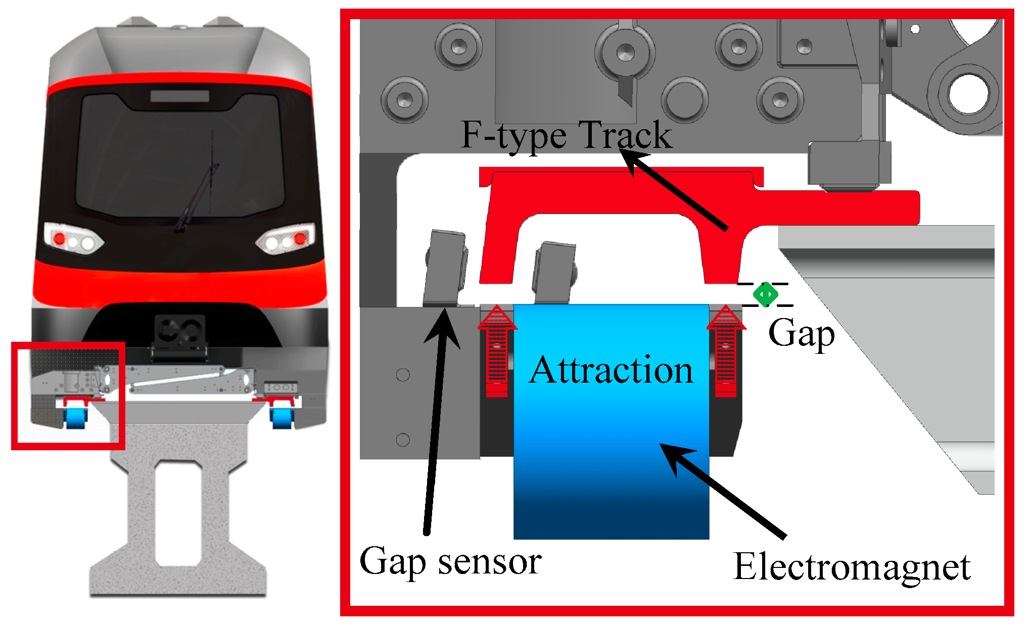
- There is no dislocation between the magnetic pole surface and the F-type track, namely, there is only vertical motion of the electromagnet relative to the track.
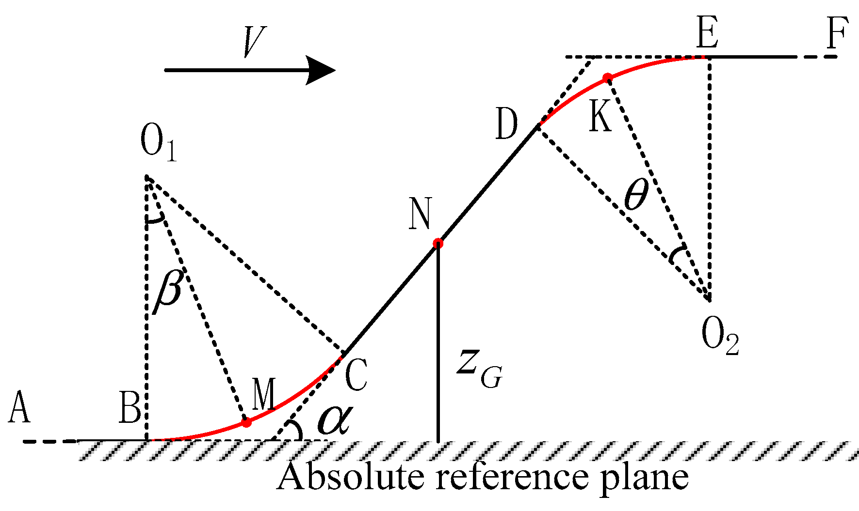
2.1. Reference Coordinate Equation
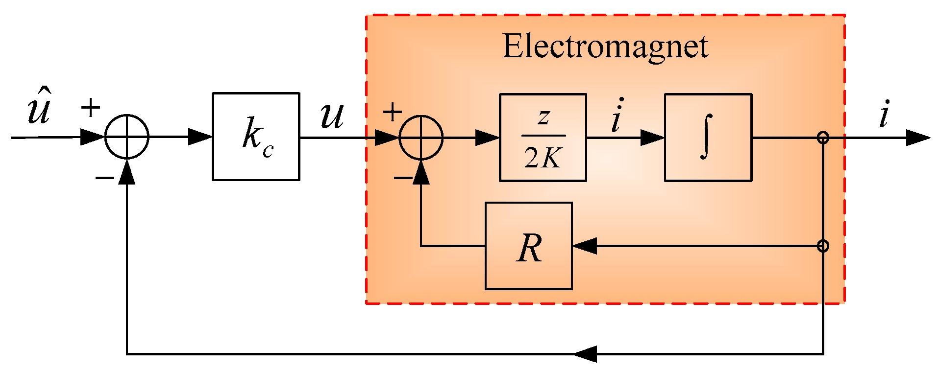
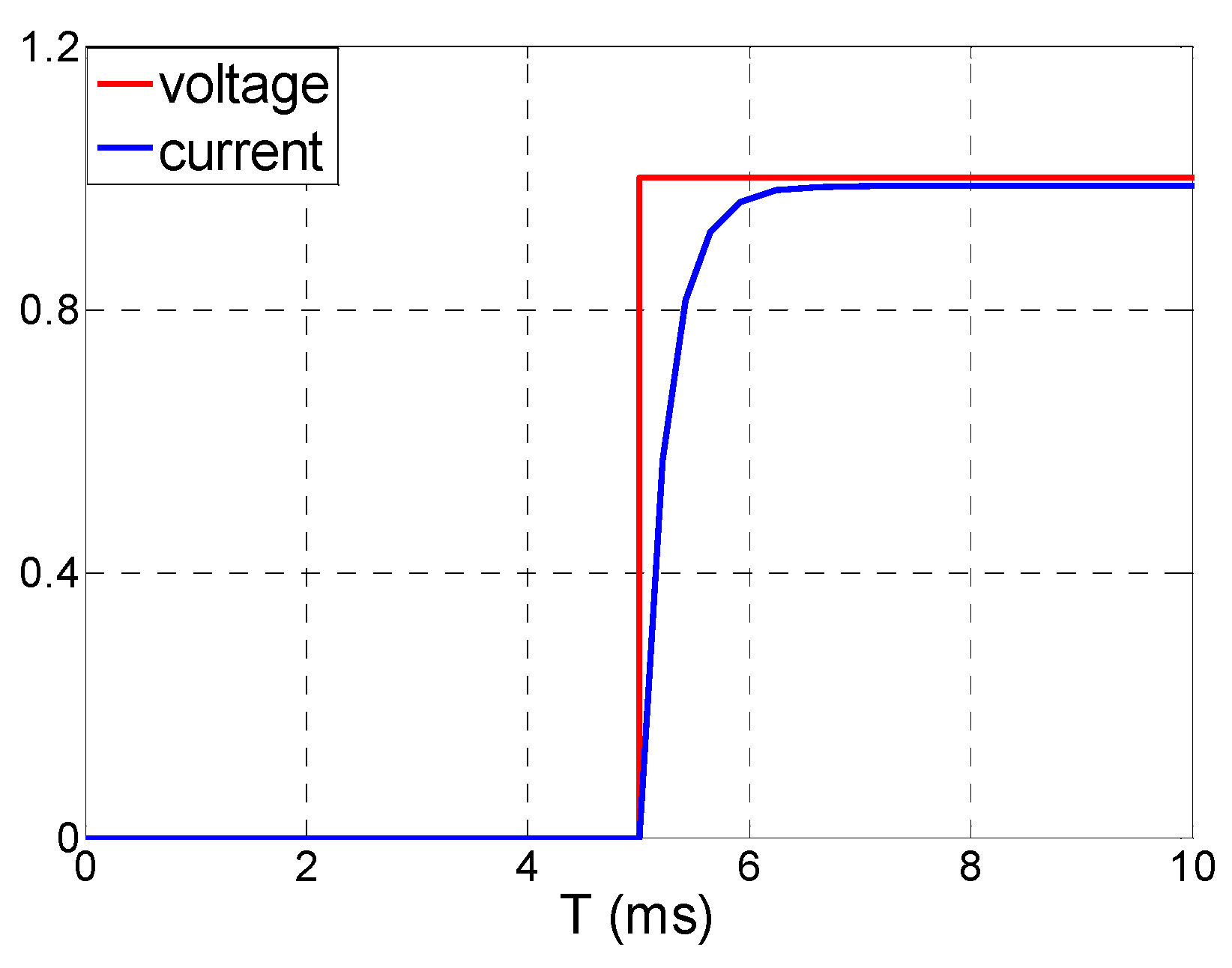
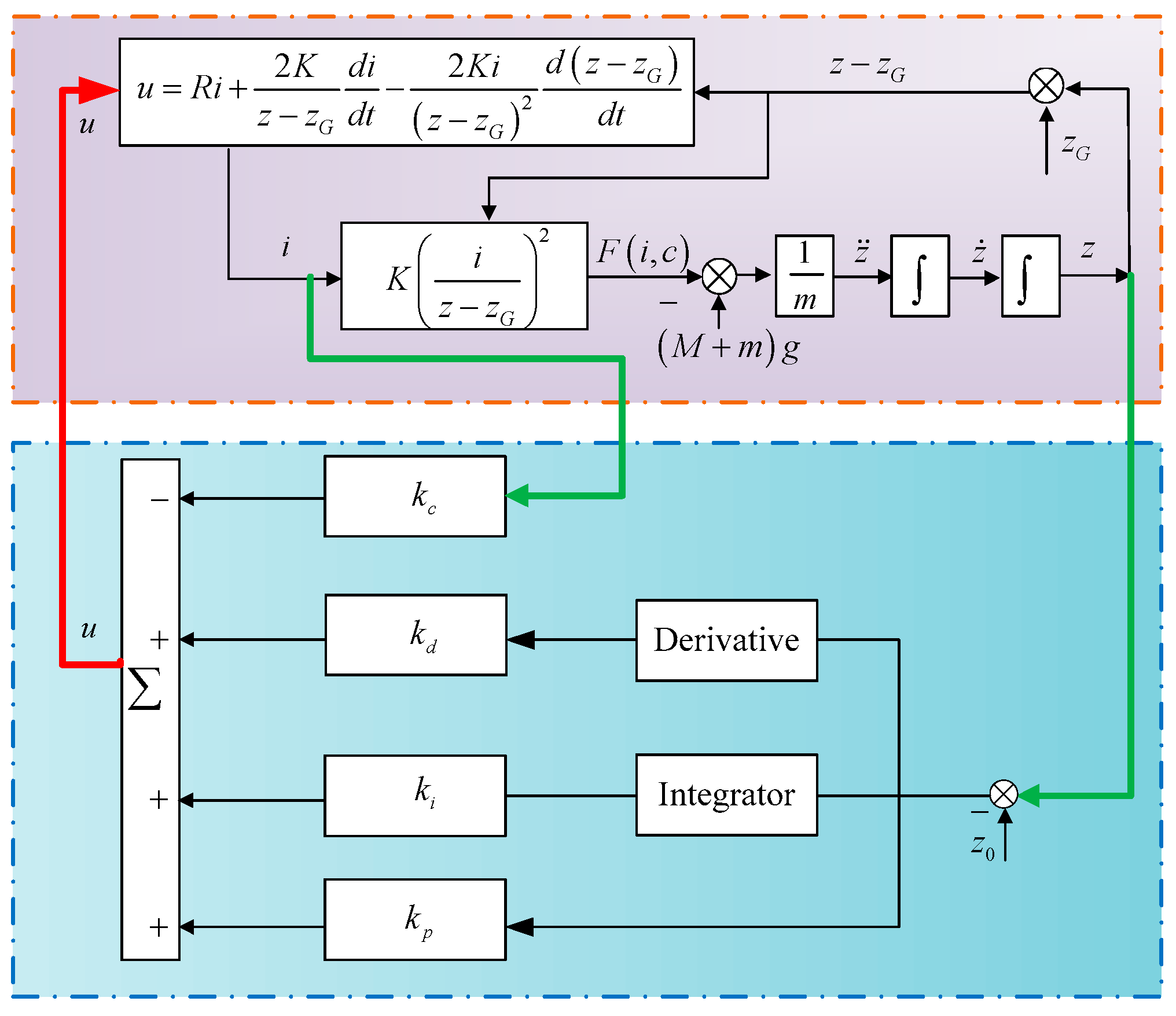
2.2. Electrical Equation
2.3. Electromagnetic Force Equation
2.4. Kinetic Equation
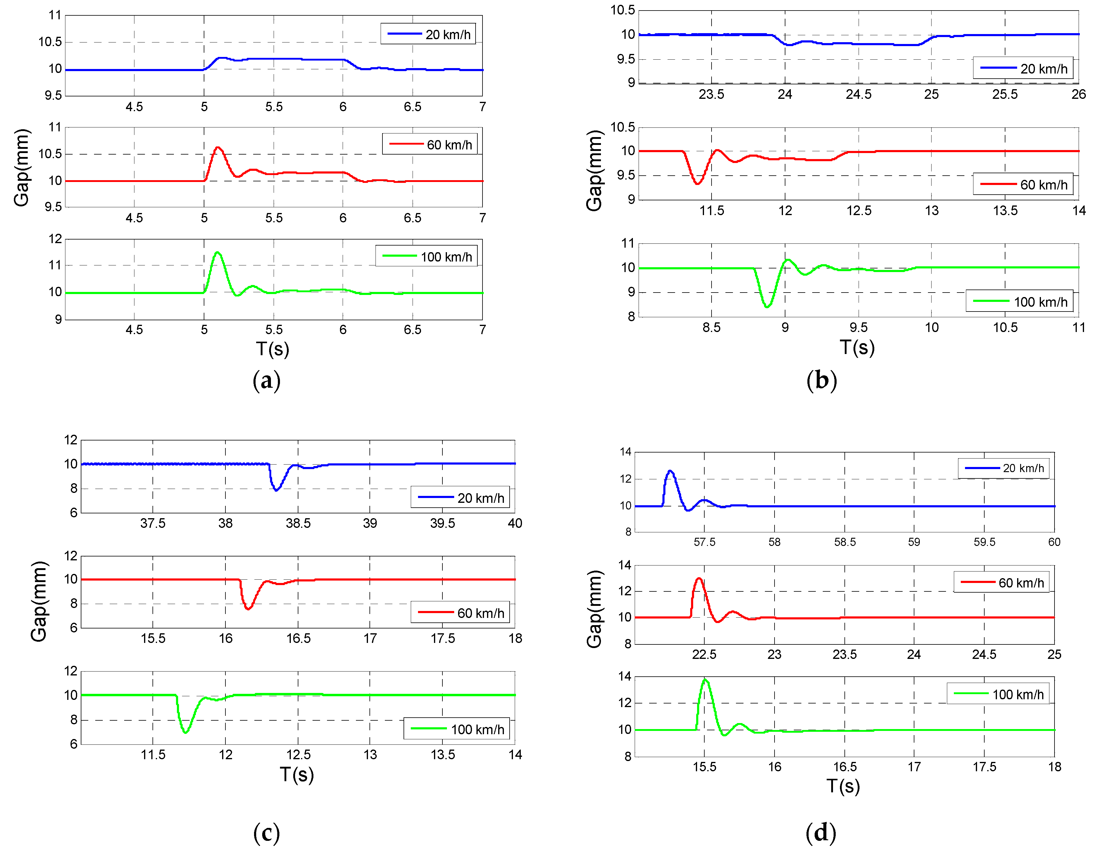
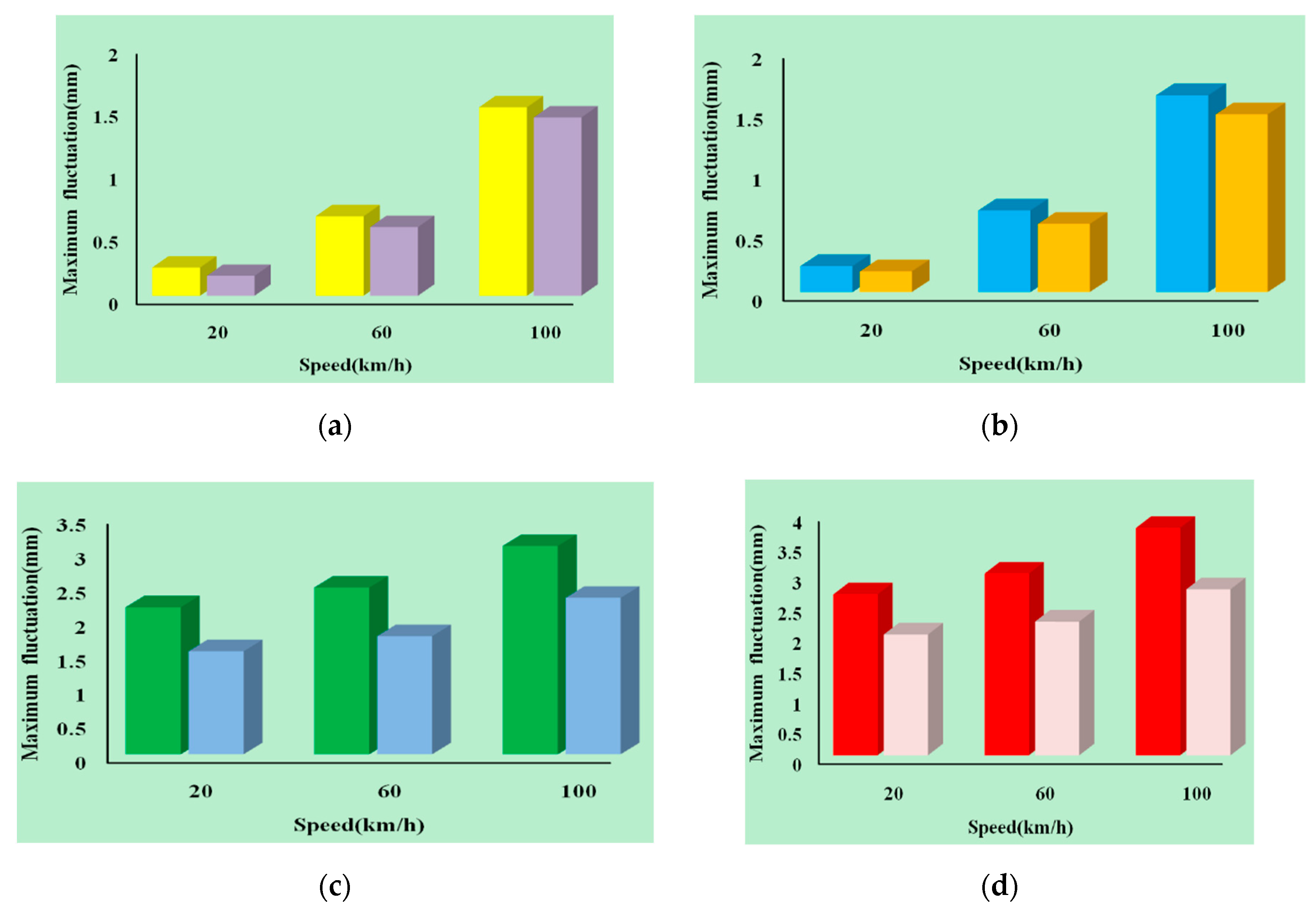
3. The Tracking Performance of Magnetic Levitation System on the Vertical Track Irregularity Condition
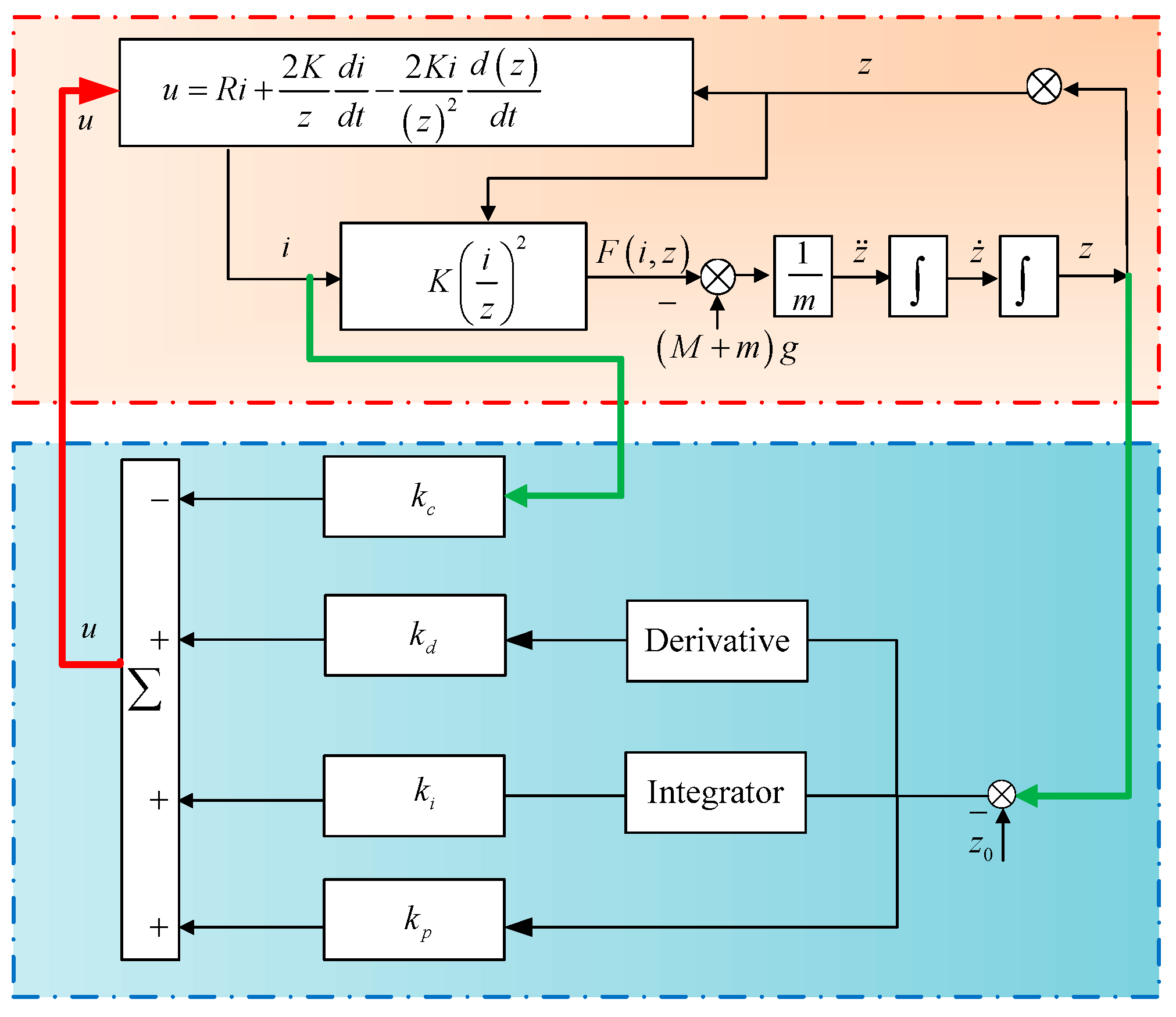
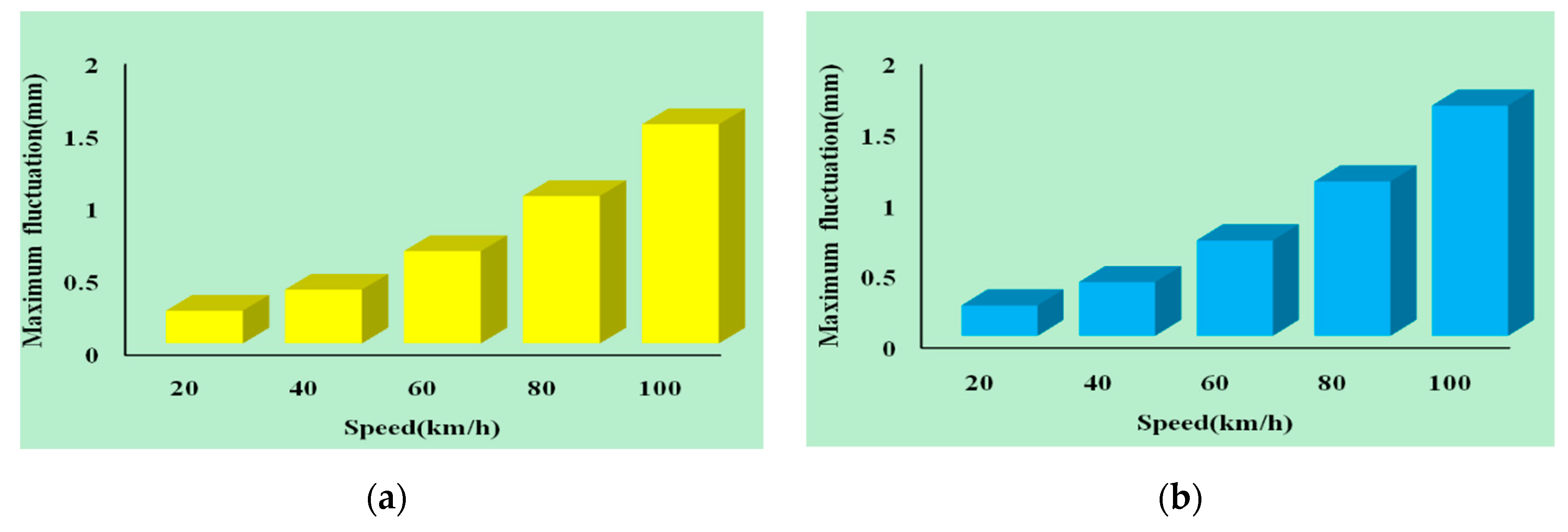
4. A New Strategy for Improving the Tracking Performance of the Magnetic Levitation System
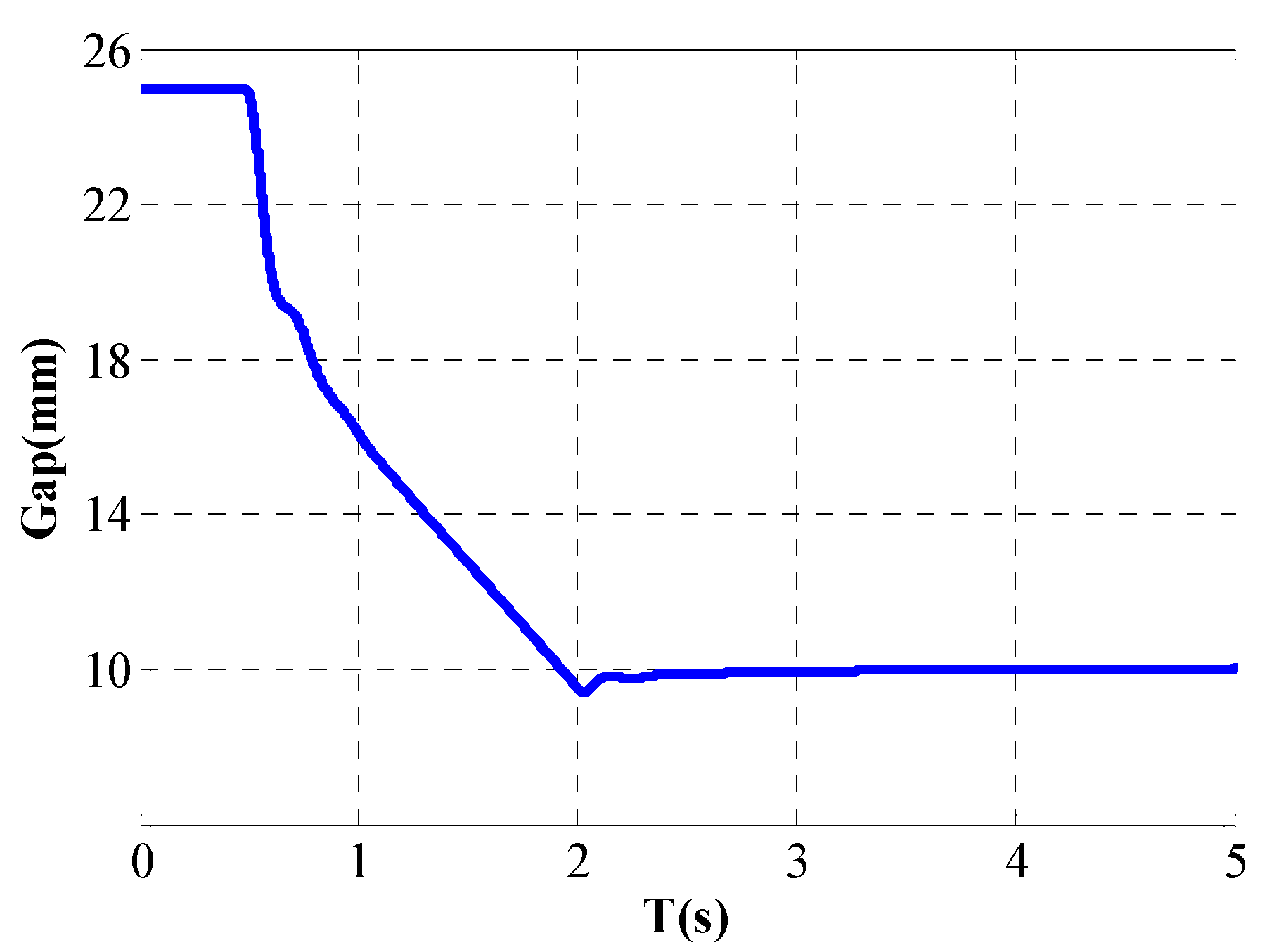
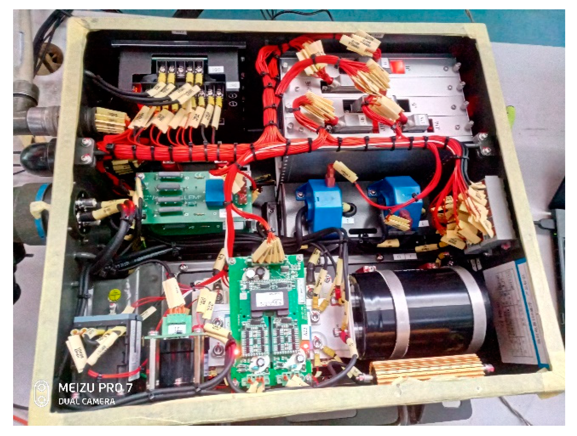
5. Implementation and Experiment
6. Discussion
7. Conclusions
Author Contributions
Funding
Acknowledgments
Conflicts of Interest
References
- Lee, H.W.; Kim, K.C.; Lee, J. Review of Maglev Train Technologies. IEEE Trans. Magn. 2006, 42, 1917–1925. [Google Scholar]
- Lin, G.; Sheng, X. Application and further development of Maglev transportation in China. Transp. Syst. Technol. 2018, 4, 36–43. [Google Scholar] [CrossRef]
- Gutierrez, H.M.; Luijten, H. 5-DOF Real-Time Control of Active Electrodynamic MAGLEV. IEEE Trans. Ind. Electron. 2018, 42, 1917–1925. [Google Scholar] [CrossRef]
- Min, D.J.; Kwon, S.D.; Kwark, J.W.; Kim, M.Y. Gust Wind Effects on Stability and Ride Quality of Actively Controlled Maglev Guideway Systems. Shock Vib. 2017, 35, 1–23. [Google Scholar] [CrossRef]
- Castellanos, M.; Miguel, L.; Galluzzi, R.; Bonfitto, A.; Tonoli, A.; Amati, N. Magnetic Levitation Control Based on Flux Density and Current Measurement. Appl. Sci 2018, 8, 2545. [Google Scholar] [CrossRef]
- Shi, J.; Fang, W.S.; Wang, Y.J.; Zhao, Y. Measurements and analysis of track irregularities on high speed maglev lines. J. Zhejiang Univ. Sci. A 2014, 15, 385–394. [Google Scholar] [CrossRef] [Green Version]
- Li, M.; Persson, I.; Spännar, J.; Berg, M. On the use of second-order derivatives of track irregularity for assessing vertical track geometry quality. Veh. Syst. Dyn. 2012, 50, 389–401. [Google Scholar] [CrossRef]
- Zhao, X.; Li, Z.; Dollevoet, R. The vertical and the longitudinal dynamic responses of the vehicle–track system to squat-type short wavelength irregularity. Veh. Syst. Dyn. 2013, 51, 1918–1937. [Google Scholar] [CrossRef]
- Yao, J.; Jiao, Z.; Ma, D.; Yan, L. High-Accuracy Tracking Control of Hydraulic Rotary Actuators with Modeling Uncertainties. IEEE/ASME Trans. Mechatron. 2014, 19, 633–641. [Google Scholar] [CrossRef]
- Ding, Z.; Li, W.; An, J.; Hao, l.; Zhang, Q. Adaptive fuzzy fault-tolerant control with guaranteed tracking performance for nonlinear strict-feedback systems. Fuzzy Sets Syst. 2016, 302, 82–100. [Google Scholar]
- Kim, W.; Shin, D.; Chung, C. The Lyapunov-based controller with a passive nonlinear observer to improve position tracking performance of microstepping in permanent magnet stepper motors. Automatica 2012, 48, 3064–3074. [Google Scholar] [CrossRef]
- Han, S.; Lee, J. Recurrent fuzzy neural network backstepping control for the prescribed output tracking performance of nonlinear dynamic systems. ISA Trans. 2014, 53, 33–43. [Google Scholar] [CrossRef] [PubMed]
- Bagheri, A.; Karimi, T.; Amanifard, N. Tracking performance control of a cable communicated underwater vehicle using adaptive neural network controllers. Appl. Soft Comput. 2010, 10, 908–918. [Google Scholar] [CrossRef]
- Tan, W. Unified Tuning of PID Load Frequency Controller for Power Systems via IMC. IEEE Trans. Power Syst. 2010, 25, 341–350. [Google Scholar] [CrossRef]
- Lee, J.S.; Choi, S.; Kim, S.S.; Park, C.; Kim, Y.G. A Mixed Filtering Approach for Track Condition Monitoring Using Accelerometers on the Axle Box and Bogie. IEEE Trans. Instrum. Meas. 2012, 61, 749–758. [Google Scholar] [CrossRef]


| Symbol | Meaning | Quantity | Unit |
|---|---|---|---|
| Mass of electromagnet | 400 | kg | |
| Mass of carriage | 1000 | kg | |
| Resistance | 1 | ||
| Number of turns | 360 | ||
| Polar area | 0.038 | m2 | |
| vacuum permeability | |||
| set gap | 10 | mm |
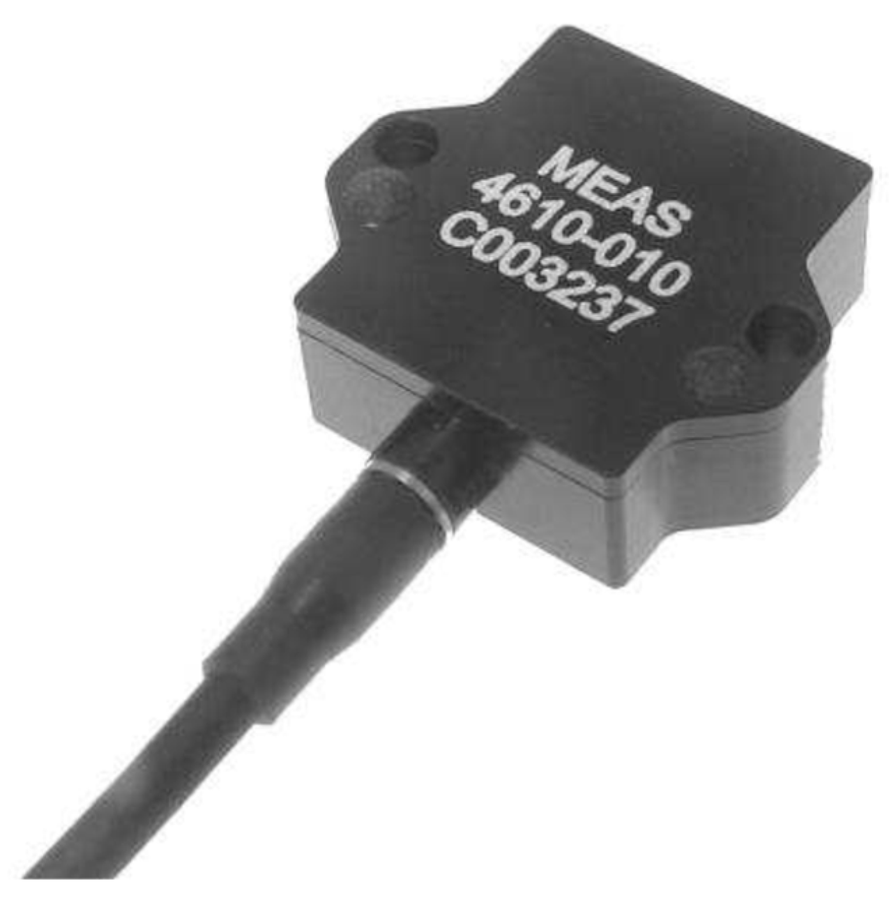
| Meaning | Quantity | Unit |
|---|---|---|
| Range | ±10 | g |
| Sensitivity | 200 | mV/g |
| Frequency Response | 0–2000 | Hz |
| Residual Noise | 400 | μV RMS |
| Non-Linearity (%FSO) | ±0.1 | / |
| Transverse Sensitivity | <3 | % |
| Damping Ratio | 0.7 | / |
| Shock Limit | 6000 | g |
© 2019 by the authors. Licensee MDPI, Basel, Switzerland. This article is an open access article distributed under the terms and conditions of the Creative Commons Attribution (CC BY) license (http://creativecommons.org/licenses/by/4.0/).
Share and Cite
Zhai, M.; Long, Z.; Li, X. A New Strategy for Improving the Tracking Performance of Magnetic Levitation System in Maglev Train. Symmetry 2019, 11, 1053. https://doi.org/10.3390/sym11081053
Zhai M, Long Z, Li X. A New Strategy for Improving the Tracking Performance of Magnetic Levitation System in Maglev Train. Symmetry. 2019; 11(8):1053. https://doi.org/10.3390/sym11081053
Chicago/Turabian StyleZhai, Mingda, Zhiqiang Long, and Xiaolong Li. 2019. "A New Strategy for Improving the Tracking Performance of Magnetic Levitation System in Maglev Train" Symmetry 11, no. 8: 1053. https://doi.org/10.3390/sym11081053