1. Introduction
As people pay increasingly more attention to environmental protection and ground transportation becomes busier, the underground excavation method is replacing the cut and cover method to become the most popular construction method [
1]. The tunnel construction method in urban areas is divided into two types, namely, the closed face tunneling method (shield method) and the open type face tunneling methods (shallow tunneling method and analysis of controlled deformation of in rocks and soils (ADECO-RS) approach). Many empirical and analytical formulas have been developed to calculate the ground displacements and stresses induced by shallow tunneling for the green-field case, which includes Peck’s empirical formula [
2,
3], the virtual image technique [
4,
5,
6], the complex variable method [
7,
8], the general series form stress function in polar coordinates [
9,
10,
11,
12], and the stochastic medium theory [
13]. Recently, the superposition methods were adopted to calculate the ground displacements and stresses induced by the combination of shallow tunneling and pile foundation loads [
14,
15].
In this research, the solutions of the ground stresses and displacements of a shallow circular tunnel considering the influence of arbitrary distributed loads on ground surface were derived using the complex variable method. Then, an application was implemented to analyze the potential plastic zone induced by shallow tunneling and loads of the ground surface structures. The results obtained from the proposed analytical prediction model were compared with the results obtained from the numerical simulations to verify the correctness of the theoretical formula. The influences of different boundary condition (different magnitudes and ranges of the arbitrary distributed loads; different symmetric boundary conditions of the tunnel perimeter) on the distribution characteristics of the potential plastic zones were also analyzed.
2. Problem Description
In this study, a symmetric elastic half-plane (
y < 0) involving a circular tunnel of radius
r at a depth h below the ground surface was considered. Tunneling will produce ground loss, which will cause a change of the deformation and stress of the surrounding strata. The boundary of a shallow circular tunnel undergoes a given distribution of displacements, i.e., uniform radial displacement and ovalization. Moreover, the arbitrary distributed loads are also considered to apply to ground surface to represent the effect of adjacent ground surface structures. The shear modulus and the Poisson’s ratio of the ground are denoted by
μ and
ν. The geometry of the problem is shown in
Figure 1.
The proposed problem was solved in the two following sections: (i) the first partial solution comprises the general formulas of the exact analytical solutions of the ground stresses and the displacements in a symmetric elastic half-plane based on the complex variable method. The solution given in this paper is a generalization of Verruijt’s solution [
7,
8], which not only considers the ground loss but also includes the effect of arbitrary distributed loads on ground surface (see
Section 3). (ii) The second partial solution comprises the derivation and the summary of the recursive relations of the Laurent series coefficients used in the complex variable method obtained from the symmetric boundary conditions of a tunnel and the arbitrary distributed loads on ground surface (see
Section 4).
3. General Formulas of the Exact Analytical Solutions of Ground Displacements and Stresses
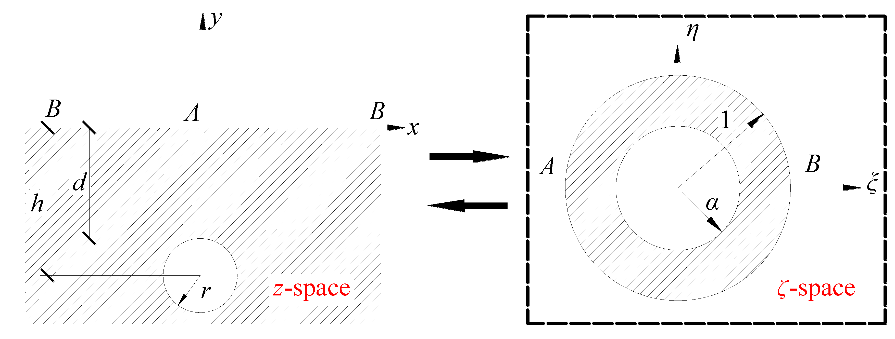
Figure 2 shows a circular tunnel located in the lower part of a symmetric elastic plane. It was assumed that the outer boundary of the ground surface suffered arbitrary distributed loads and the inner boundary of the tunnel profile underwent a specific symmetric distribution of convergence deformation. According to the complex variable method, the original domain in the
z-plane (physical plane) was mapped conformally onto an annular region on the
ζ-plane (mapped plane) with the following conformal transformation:
where
α was obtained by
In the
z-plane, the solutions of the ground stresses and displacements due to the tunnel construction were donated by two analytic functions,
φ1 (
z) and
ψ1 (
z), and they were obtained as follows:
where
μ,
κ, and
i are the shear modulus of the ground material, a related parameter for Poisson’s ratio ν, and the imaginary constant, respectively.
By virtue of the conformal transformation function, the two analytic functions,
φ1(
z) and
ψ1(
z), could be transformed to the functions in terms of
ζ as follows:
Moreover,
φ(
ζ) and
ψ(
ζ) would be expanded in a Laurent series in the
ζ-space in the following equations due to the characteristics of the analytical function.
where the Laurent series coefficients
a0,
ak,
bk,
c0,
ck, and
dk could be calculated by the recursive relations obtained from the boundary conditions.
4. Recursive Relations and Laurent Series Coefficients for the Proposed Model
The solution of displacements and stresses obtained above is a generalization of Verruijt’s solution, which not only considers the ground loss but also includes the effect of arbitrary distributed loads on the ground surface. In this section, the recursive relations from specific boundary conditions are derived, and the Laurent series coefficients are summarized for the boundary deformations of a tunnel and the arbitrary distributed loads on ground surface.
4.1. The Outer Boundary of the Ground Surface
The outer boundary of the ground surface
y = 0 underwent arbitrary distributed loads. This gave the following equation:
This equation can be transformed to the
ζ-plane and expressed as the form
Then the boundary Condition (7) can be elaborated in terms of Laurent series coefficients as follows:
Therefore, the coefficients
c0,
ck, and
dk satisfy the following recursive relations:
where the related coefficients
ek are in Fourier series terms in Equation (9), as seen in
Appendix A.
4.2. The Inner Boundary of the Tunnel Profile
In general, the inner boundary of a tunnel profile will undergo convergence deformation. Researchers have proposed a variety of the specific symmetric distributions of the convergence deformation for different soil types or engineering conditions. Verruijt and Booker [
5] stated that a shallow tunnel profile undergoes a combination deformation of uniform convergence and ovalization. In this research, considering the buoyancy effect, the vertical translation was incorporated into the convergence deformation of a shallow tunnel [
11].
Figure 3 shows the four possible forms of boundary conditions (B.C. 1, B.C.2, B.C.3, and B.C.4) that are more in accord with engineering practice.
The boundary condition for a shallow tunnel profile in the
ζ-plane is
After some elaborations, the symmetric boundary Condition (10) now gives
Therefore, the coefficients
a0,
ak, and
bk are calculated using the following equations integrating the related coefficients
Ak in Laurent series terms
where the
Ak variables are in Laurent series terms in Equations (13) and (14), seen in
Appendix B.
5. An Application of the Derived Exact Analytic Solutions
5.1. Prediction of the Distribution Characteristics of the Potential Plastic Zone
It is often unavoidable that urban subway tunnels are constructed adjacent to ground surface structures, e.g., existing buildings. It is important to predict the degree of interactions between the tunnel construction and the ground surface structures. Generally, the degree of the interactions will be evaluated with a prediction of the distribution characteristics of the potential plastic zone. In this paper, the practical problem of the construction of shallow subway tunnels adjacent to surface building is simplified to the mechanics model, as shown in
Figure 4.
By combining the exact analytical solutions of the ground stresses obtained from this research and the Mohr–Coulomb yield criterion, an equation for the boundary of the potential plastic zone due to shallow tunneling adjacent to the surface building was obtained. Based on the approach presented above, the boundaries of the potential plastic zones induced by tunneling adjacent to the surface building were drawn using MATLAB software. The assumed parameters in the presented calculations were silt clayey soil with a cohesion c = 30 kPa and an angle of internal friction φ = 30°. The radius of the circular tunnel was 3 m, and the center depth h was 10 m. The uniform convergence u0 was 30 mm. The magnitudes of the distributed loads q were 100, 200, and 300 kN/m, and the ranges of the distributed loads (a0, b0) were (0 m, 7 m), (2 m, 9 m), and (4 m, 11 m).
5.2. Influences of Different Magnitudes and Ranges of Arbitrary Distributed Loads on the Potential Plastic Zones
The influences of the different magnitudes and ranges of arbitrary distributed loads on the distribution characteristics of the potential plastic zones are analyzed in
Figure 5 and
Figure 6.
The influences of three different magnitudes of the distributed loads
q = 100, 200, and 300 kN/m on the distribution characteristics of the potential plastic zones are plotted in
Figure 5. The results show that the potential plastic zones around the tunnel and around the ground surface structure coalesced when the magnitude of distributed load
q was big enough, while if the magnitude of the distributed load
q was relatively small, the potential plastic zones separated into two parts. Moreover, the plastic zone without distributed load obtained from the solution of Verruijt [
7,
8] is also added in
Figure 5 to allow for interpretation of the superiority of the analytical solution proposed in this paper.
Figure 6 presents the influences of three different ranges of distributed loads (
a0,
b0) = (0 m, 7 m), (2 m, 9 m), (4 m, 11 m) on the distribution characteristics of the potential plastic zone induced by tunneling. It can be observed that when the range of distributed loads (
a0,
b0) was close enough to the tunnel, the tunneling-induced potential plastic zones around the tunnel and the potential plastic zones around the distributed loads coalesced.
In general, the results show that the larger the pile loads and the closer the relative position between the tunnel and the distributed loads, the more distinct the coalesced trends of the potential plastic zones around the tunnel and the potential plastic zones around the distributed loads.
5.3. Influences of Different Tunnel Boundary Conditions on the Potential Plastic Zones
The influences of different tunnel boundary conditions (B.C.1, B.C.2, B.C.3, and B.C.4) on the distribution characteristics of the potential plastic zones are shown in
Figure 7. The results indicated that different tunnel boundary conditions greatly affected the distribution characteristics of the potential plastic zones. More attention should be paid to selecting tunnel boundary conditions because the ovalization and the vertical translation significantly affect the shape of the potential plastic zones.
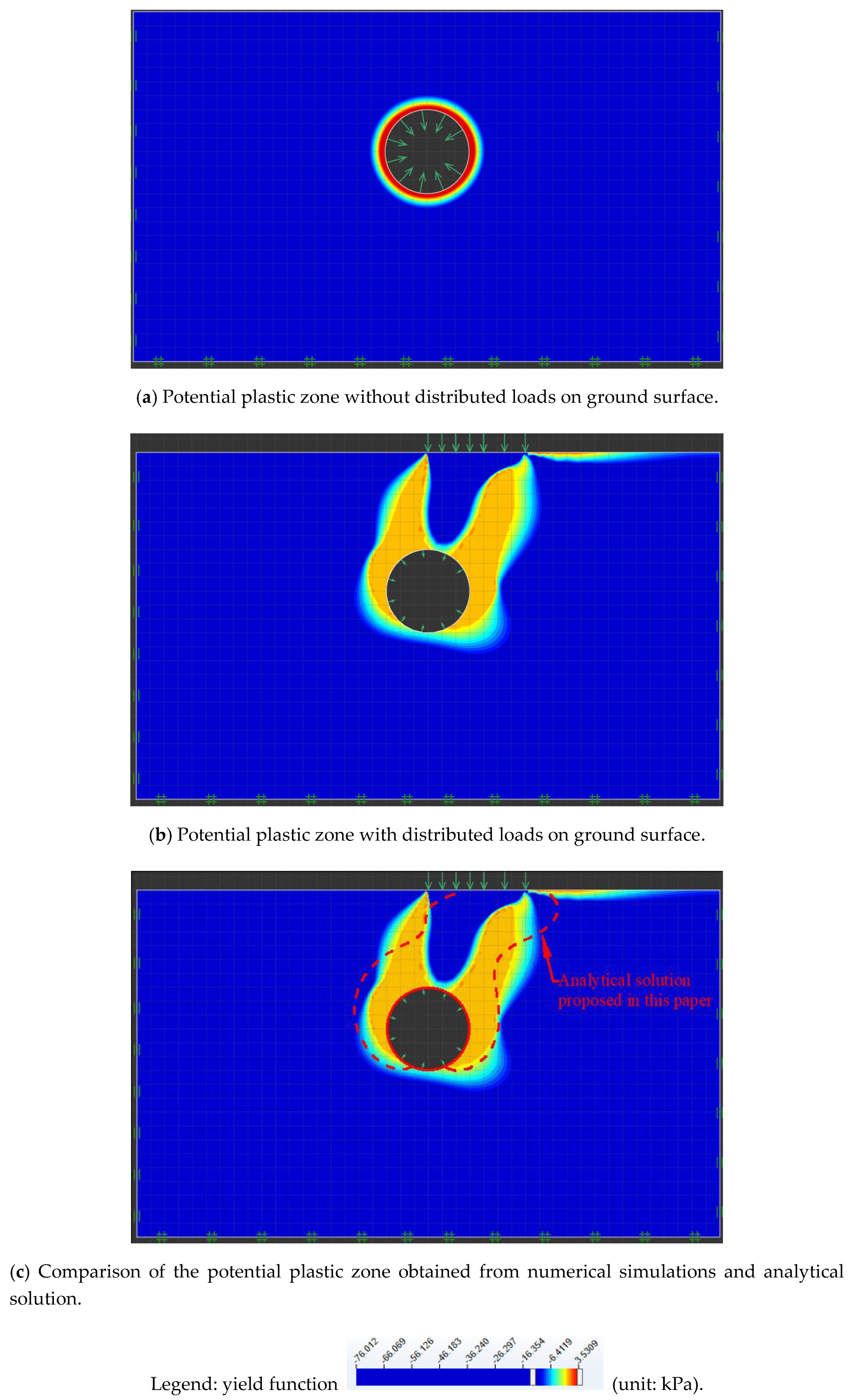
5.4. Verification of the Potential Plastic Zone Obtained from the Derived Analytical Solutions with the Numerical Simulations
Numerical simulations were performed by using the professional software OptumG2 [
16] based on identical parameters.
Figure 8a,b indicate the potential plastic zone for the green-field and for the condition with arbitrary distributed loads on ground surface obtained from the numerical simulations.
Figure 8c presents the comparison of the potential plastic zone obtained from numerical simulations and analytical solution, which shows that the range of potential plastic zone are similar to each other. It is worth pointing out that there was still a difference between the potential plastic zones obtained from the derived analytical solutions with the numerical simulations. The boundary contour of the potential plastic zone obtained from the derived analytical solutions was obtained by combining the yield criterion with the analytical solution of the elastic hypothesis, while the numerical simulation could directly calculate the stress in the elastic and plastic zones and obtain the potential plastic zone.
6. Conclusions
In this research, the solutions of the ground stresses and displacements of a shallow circular tunnel in a symmetric elastic half-plane under arbitrary distributed loads on ground surface were derived using the complex variable method. Then, an application was implemented to analyze the potential plastic zone caused by shallow tunneling adjacent to the ground surface structures. The influences of different boundary condition (different magnitudes and ranges of the arbitrary distributed loads, different symmetric boundary conditions of the tunnel perimeter) on the distribution characteristics of the potential plastic zones were analyzed. The main conclusions were as follows.
- (1)
The potential plastic zones around the tunnel and around the ground surface structure coalesced when the magnitude of the distributed load q was big enough, while if the magnitude of the distributed load q was relatively small, the potential plastic zones separated into two parts.
- (2)
If the range of the distributed loads (a0, b0) was close enough to the tunnel, the tunneling-induced potential plastic zones around the tunnel and the potential plastic zones around the distributed loads coalesced.
- (3)
The results indicated that different symmetric tunnel boundary conditions greatly affected the distribution characteristics of the potential plastic zone.


