Article

Sensor Fusion Based Pipeline Inspection for the Augmented Reality System

1
Graduate School of Advanced Imaging Science, Multimedia and Film, Chung-Ang University, Seoul 156-756, Korea
2
ICT Convergence and Integration Research Division SOC, Research Institute, Korea Institute of Construction Technology, Gyeonggi-do 411-712, Korea
*
Author to whom correspondence should be addressed.
Symmetry 2019, 11(10), 1325; https://doi.org/10.3390/sym11101325
Submission received: 7 October 2019 / Revised: 21 October 2019 / Accepted: 21 October 2019 / Published: 22 October 2019

Abstract

:
Augmented reality (AR) systems are becoming next-generation technologies to intelligently visualize the real world in 3D. This research proposes a sensor fusion based pipeline inspection and retrofitting for the AR system, which can be used in pipeline inspection and retrofitting processes in industrial plants. The proposed methodology utilizes a prebuilt 3D point cloud data of the environment, real-time Light Detection and Ranging (LiDAR) scan and image sequence from the camera. First, we estimate the current pose of the sensors platform by matching the LiDAR scan and the prebuilt point cloud data from the current pose prebuilt point cloud data augmented on to the camera image by utilizing the LiDAR and camera calibration parameters. Next, based on the user selection in the augmented view, geometric parameters of a pipe are estimated. In addition to pipe parameter estimation, retrofitting in the existing plant using augmented scene are illustrated. Finally, step-by-step procedure of the proposed method was experimentally verified at a water treatment plant. Result shows that the integration of AR with building information modelling (BIM) greatly benefits the post-occupancy evaluation process or pre-retrofitting and renovation process for identifying, evaluating, and updating the geometric specifications of a construction environment.

1. Introduction

Building information modelling (BIM) is an intelligent process that provides information about the construction and management of building infrastructures. BIM includes a complex multiphase process that gathers information from multiple sources to model the components and tools used during the construction process [1,2,3]. BIM adoption in the construction process can help achieve greater building construction efficiency [4]. One of the greatest benefits of BIM technology is the three-dimensional (3D) visualization of the construction environment, which makes it easier for professional engineers to analyze the actual details of architectural, structural, and geometrical information [5]. It also enables a more intuitive understanding, facilitates timely communication, and improves error checking in designs. Furthermore, mapping 3D models with intelligent systems can provide immersive visualization as a virtual experience through computer-aided simulation.
Although 3D visualization using BIM technology allows engineers to efficiently visualize a construction environment, the overall effectiveness of real-time communication within the BIM environment is restrained due to the limited sense of immersion in virtual environments [6]. A previous research review showed that improving visualization and communication in the construction environment greatly helps engineers in terms of productivity and safety of construction processes [7]. Improving safety in the construction phase is described by Chantawit et al. [8] and Li et al. [9]. In the context of easy access and utilization of information in a BIM environment, augmented reality (AR) has been identified as an optimal solution due to its technology that superimposes the virtual objects onto the physical world. Also, BIM + AR can provide effective visualization of BIM data with a close connection in a physical context [10]. AR systems have already been successfully explored for various applications in the fields of architecture, engineering, and construction/facilities management (AEC/FM) [11,12,13,14,15,16]. There are also examples of using VR for BIM applications, as introduced by Sanz et al. [17], to provide training for assembly processes.
Few investigations have been carried out with respect to the utilization of BIM + AR at construction sites to guide professional workers in real-time. There is a limited level of realism due to a lack of sensor feedback, including the dimensions, textures, and spatial locations of the environment, as well as the confined utilization of real-time sensor information. Therefore, there is little perceptual and cognitive benefit to onsite workers. Also, digital biding of information in BIM is limited due to a lack of interactions between the real world and the virtual world. However, with efficient communication and onsite information sharing, AR has the potential to assist site engineers and construction workers in the BIM environment. Although the conventional role of AR is visualization, providing geometrical information and allowing for interactions with the data provided on site (virtual model) will also greatly benefit users (as shown in Figure 1).
This paper presents Light Detection and Ranging (LiDAR) and Camera fusion system for the pipeline virtual retrofitting process in BIM. The pose of the prebuilt 3D point cloud is aligned according to the pose of the real environment scene using real-time LiDAR scan point cloud by employing the registration algorithm. Next, a Red-Green-Blue (RGB) image of the prebuilt 3D point cloud is generated using the external camera parameters and merged with frames of a real-time video. To establish correspondence between the data from these two different sensing devices (i.e., the LiDAR and camera fusion), calibration between the camera and LiDAR performed prior to correspondence establishment. Additionally, identification of the geometric specifications of pipes using real-time LiDAR scan data helps workers choose specific targets for retrofitting. Finally, the proposed approach can be utilized in pipeline pre-retrofitting applications via the integration of pre-generated 3D models for upgradation or modification in an existing environment.
The rest of this paper is organized into the following sections: Section 2 presents a literature review of the research relevant to AR in BIM engineering and point cloud registration methods. In Section 3, the proposed methods, 3D point cloud alignment, 3D point cloud to 2D image extraction, and video alignment are presented. Virtual retrofitting is presented in Section 4, and Section 5 presents the experimental verification and results.

2. Literature Review
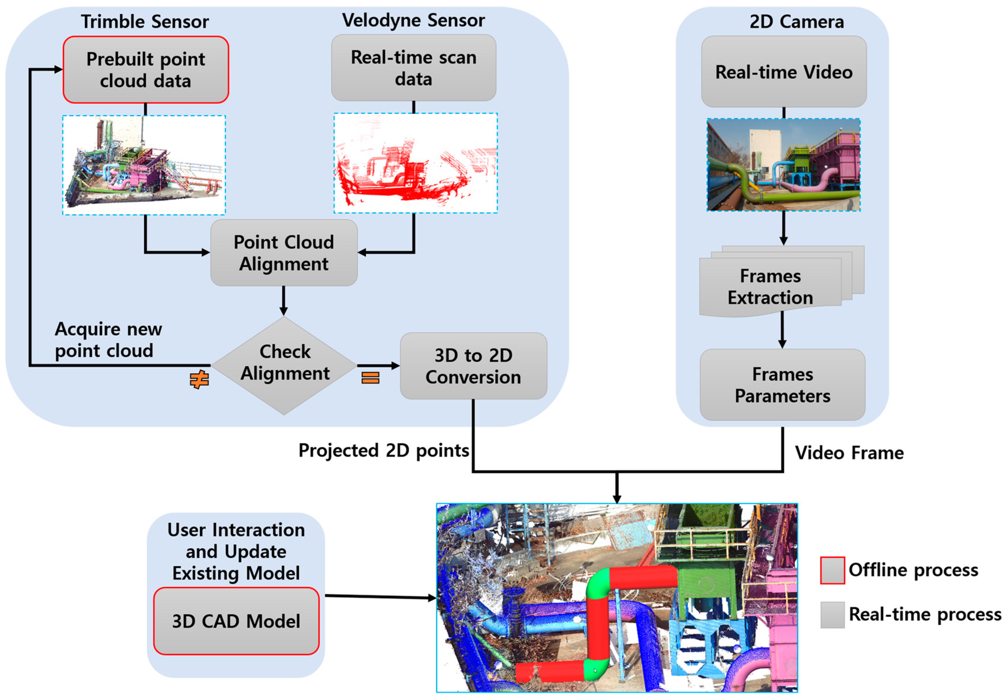
Augmented reality systems for BIM applications have been gaining increased attention from researchers of late. In recent years, many methodologies have been proposed for BIM + AR technologies. However, there is still a lack of sufficient investigations and insight into how real-time information can be utilized in BIM with an AR system. In this section, we discuss some of the AR systems proposed for BIM applications.
A recent study presented by Tabrizi et al. [18] concludes that BIM + AR can enhance an information retrieval, task efficiency, and productivity in building construction. The augmented reality proposed by Wang et al. [6] highlights the need for a structured methodology to integrate AR into BIM applications. In their paper, the authors concentrated more on assembling a new pipe plant. The proposed system helped workers find locations to place components at the construction site. Identification of object specifications in the model were displayed based on a QR code attached to an object. Each component in the model had a unique QR code with an associated list of attributes. The authors also investigated how BIM can be extended onsite by using AR technology.
Based on a post occupancy evaluation (POE) study, an AR system for BIM design applications was introduced by Freits and Regina [19]. In their paper, the geolocation was identified to augment a virtual object in the scene by considering the global positioning system (GPS) and digital compass data. Based on user movement, the position of the virtual object was maintained according to the point of view of the user. The accuracy of the method proposed in this paper depends on the position data obtained via GPS.
In Gupta et al. [20] proposed an AR system using LiDAR point cloud data to display dimensional information of objects on mobile phones. In their paper, the authors described an overall system based on two main steps. In the first step, the correspondence between the LiDAR point cloud data and the camera image was established using interior and exterior orientation parameters of the mobile camera and the coordinates of the LiDAR data points. A pseudo intensity image was generated from the 3D point cloud registered with the camera image by using an image registration method (SIFT) to ensure the correspondence between the point in the point cloud and the point (pixel) in the image. Their method utilizes random sample consensus (RANSAC) to estimate the homography for the projective transformation matrix. Estimation of the transformation matrix using RANSAC is an iterative process that requires more computational time. The authors also mentioned that false matches resulting from the SIFT findings should be removed prior to the RANSAC process. Estimating the orientation based on image feature analysis directly affects the computational time. Thus, adopting this method in real-time applications is difficult because of the computational time. The authors did not discuss the estimation of dimensional information of the objects.
Bae et al. [11] proposed a mobile AR system for context-aware construction and facility management applications. The system presented in their paper does not require any RF-based location tracking (e.g., GPS or WLAN) or optical fiducial markers for tracking a user’s position. Instead, a user’s location and orientation are automatically derived by comparing photographs from the phone with the 3D point cloud model created from a set of site photographs. Also, the authors described a detailed procedure for 3D reconstruction based on the structure-from-motion (SfM) algorithm, which estimates the 3D position of image features through feature extraction, matching, initial triangulation, and an optimization process.
LiDAR scanning systems acquire point clouds with enhanced reliability in three dimensions. When a similar scene or the environment of an area of interest is acquired multiple times from multiple views, alignment problems can arise depending on the application. In the last two to three decades, many efficient registration algorithms [21] have been introduced to address difficulties related to scenes or object registration; these problems can be classified into two categories depending on the use of the registration targets, i.e., rigid or non-rigid scenes or objects. In the case of rigid targets, a homogeneous transformation is applied to rigid surfaces, which can be modelled using six degrees of freedom. In the other case, non-rigid targets require the application of a coarse transformation to shapes or scenes, which vary with time.
BIM-based AR maintenance system (BARMS) [22] a building information modeling-based augmented reality maintenance system is a smartphone-based platform for an illumination function in darkness, showing a safe maintenance route and projecting BIM models. The BIM models are projected into a real environment for maintenance workers to analyze the correct locations of pipes. The proposed approach has the drifting problem which affects the positioning accuracy of application-anchoring locations.
The scene or environment in our proposed method comes under the first category, i.e., rigid targets. Currently, most state-of-the-art applications use the standard iterative closest point (ICP) algorithm introduced by Besl et al. [23] (or one of its variant algorithms) for rigid target alignment; these algorithms are superior in terms of their precision, performance, and robustness [21] under a set of restrictions. Initially, we utilized the standard ICP algorithm in the proposed method for the alignment of the point cloud [23]. ICP considers pairs of nearest points in the source and target point cloud data sets as correspondences and treats every point as having a corresponding point. ICP tries to find the optimal transformation between two datasets by iteratively minimizing a distance error metric.
A main disadvantage of the traditional standard ICP algorithm is that it assumes that the source cloud is acquired from a known geometric scene instead of being acquired through noisy measurements. However, it is generally impractical to obtain a perfect point-to-point alignment result, even after complete merging of the target and source data, due to discretization errors. Chen et al. [24] proposed the point-to-plane registration algorithm by considering that most of the range measurements are commonly sampled from a locally planar surface. The point-to-surface ICP algorithm proposed by Low et al. [25] tried to manage the discretization differences by modifying its constraint by permitting points to aggregate along the surface. Alshawa et al. [26] proposed a line-based matching ICP variant called the iterative closest line (ICL). In ICL, line features are obtained from range scans that are aligned to achieve the rigid body transformation.
Segal et al. [27] proposed a Generalized-ICP (G-ICP) algorithm that improves ICP by using the underlying surface structure of the point cloud to reject poorly corresponding points. G-ICP performs plane-to-plane matching by a probabilistic interpretation of the minimization process such that structural information from both the source cloud and the target cloud can be incorporated easily into the optimization algorithm.
In our previous work [28], we proposed a prototype framework for pipeline virtual retrofitting with a 4-in-1 alignment approach. In previous work, Velodyne VLP-16 LiDAR was used for prebuilt data acquisition as well as for real-time scan data and an external GoPro camera was used for the video capture. The basic setup and preliminary results demonstrated in an indoor environment provide the 4-in-1 alignment approach that can be utilized for the pipeline retrofitting applications. The current proposed work extends the previous work [28] by optimizing point cloud alignment algorithm for better time efficiency and accuracy. Further, LiDAR and camera calibration steps are enhanced with sensor fusion technique for pipeline inspection and retrofitting for the AR system in BIM application.

3. Proposed Method

This section describes the proposed AR system for pipeline retrofitting in BIM using LiDAR point cloud data and a camera scene fusion, as shown in Figure 2. This section begins with a description of the 3D prebuilt point cloud alignment using a real-time scan point cloud. Next, a prebuilt 3D point cloud was linked to the camera scene using the proposed approach. Step-by-step processes of aligning the prebuilt 3D point cloud information in the camera scene are also described in detail.
The proposed method includes two different scanning setups for the acquisition of the 3D prebuilt and real-time point cloud, as shown in Figure 3. The commercial Trimble TX5 3D laser scanner [29] was utilized to acquire the detailed 3D point cloud of the water treatment environment. As shown in Figure 3a, the processed 3D point cloud of the pipeline plant includes detailed information related to the environment. However, in the proposed method, more emphasis is given to pipeline parts than in the complete point cloud model, wherein only pipeline parts are segmented from the complete point cloud model for further processing. Figure 3b shows the segmented pipeline point cloud data highlighted in blue.
The Velodyne LiDAR PUCK (VLP-16) [30] 3D scanning platform is used to acquire the scan point cloud. Data from the Velodyne platform are only used for aligning the prebuilt cloud because a real-time scan point cloud of the environment (as shown in Figure 3c) is sufficient.

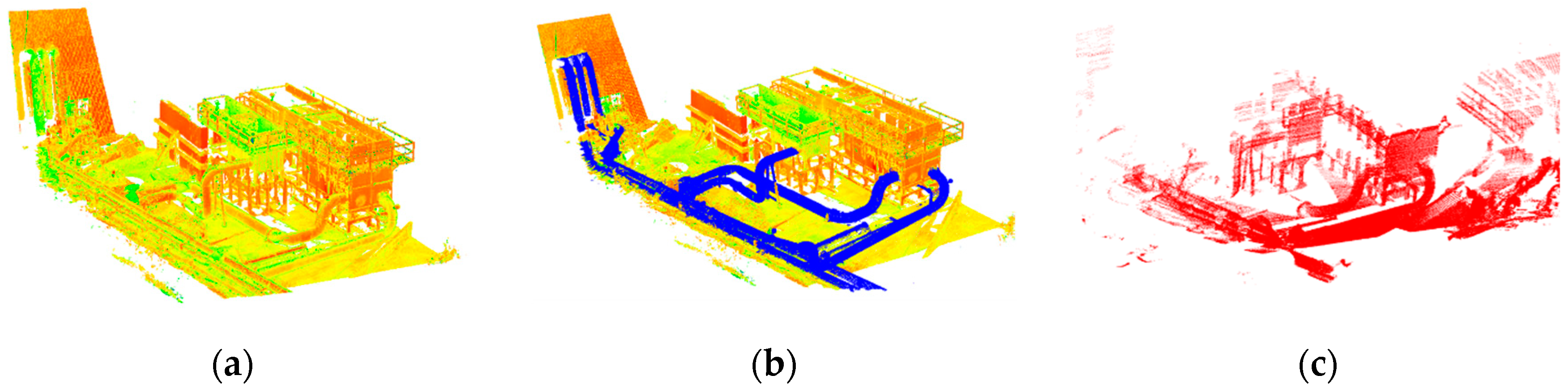
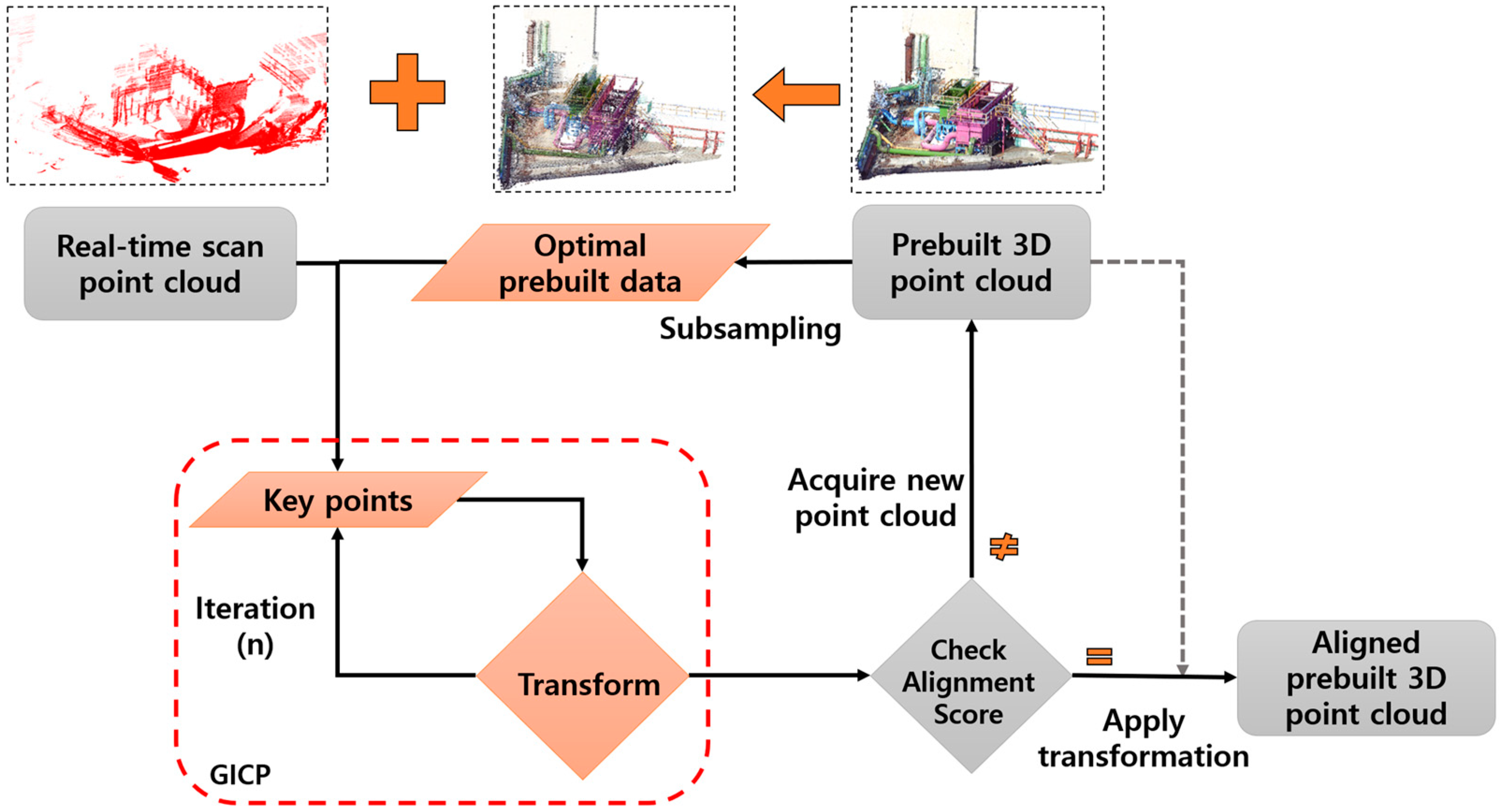
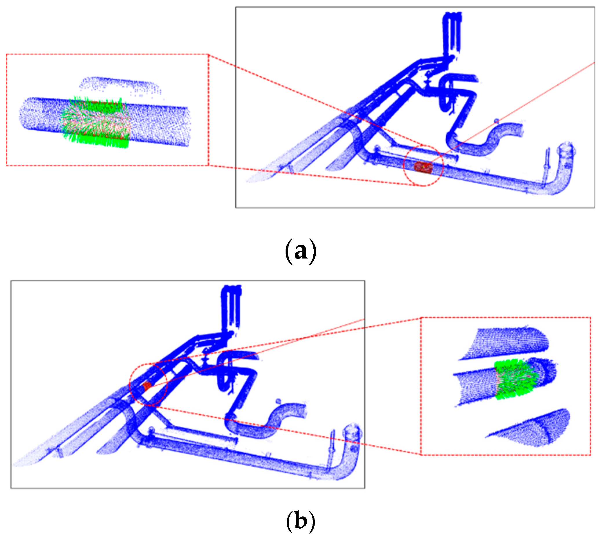
3.1. Real-Time Point Cloud Alignment

The accuracy and time efficiency of any AR system greatly relies on the performance of the localization and real-time alignment process used for mixing real scenes with virtual scenes. In the proposed AR framework, predefined positions are used to localize the platform. Therefore, the accuracy and time efficiency of the AR system directly depends on the performance of the real-time alignment process.
Many techniques have been implemented for pairwise 3D point cloud registration, including well-known ICP-based methods. In the proposed approach, the G-ICP [27] algorithm is used with an initial optimization for alignment of a prebuilt point cloud data set from real-time scan point cloud data (Figure 4).
Consistently aligning pairwise 3D point cloud data views into a complete model is referred to as registration. We mainly focused on the alignment of prebuilt point cloud data with the physical world in a global coordinate framework, regardless of pairwise registration. Aligning pairwise point cloud data from different sensors is complicated because each sensor has a different coordinate system and scale. Before the refined alignment, the prebuilt point cloud data from its local coordinate ( P l o c a l ) is initially shifted and scaled offline to map with the real-time scan point cloud data’s coordinate system ( P g l o b a l ) , as given in Equation (1).
P g l o b a l = ( P l o c a l S ) T
Here, T ( x , y , z ) is the global shift (translation matrix), S is the global scale matrix, and P is a 3D point.
However, the goal of our approach is to align the prebuilt point cloud data with respect to the relative position and orientation of a physical model in a global coordinate framework using a real-time scanned point cloud from a LiDAR sensor. Furthermore, if there are any changes in the plant then respective changes are updated (i.e. acquiring prebuilt point cloud again). As shown in the block diagram (Figure 4), prebuilt data is optimized via subsampling to minimize the point density for the correspondence grouping (the selection of key points). Using the prebuilt data for the alignment directly is computationally expensive for real-time alignment. This is because the correspondence grouping process requires a comparison between every prebuilt point and every point in the real-time scan data. Figure 5a,b show the complete prebuilt data set and the subsampled point cloud data, respectively, and Figure 3c shows the real-time scan point cloud data from a LiDAR sensor.
To align the prebuilt point cloud with the physical environment in the proposed method, the previously mentioned prebuilt point cloud is optimized via random sampling to improve the key point detector performance in the correspondence grouping. The random sampling method [31], which is implemented in the PCL library [32], is used to achieve the required optimal points.
P o = r a n d o m s a m p l e ( P p )
Here, P o are the optimal sampled prebuilt points and P p is the original prebuilt point.
After obtaining the optimal points by sampling, the G-ICP technique is used for alignment by keeping the rest of the algorithm unchanged. First, the transformation matrix is computed by considering optimal prebuilt point cloud data ( P o ) and real-time scan point cloud data ( P r ) using Equation (3):
T = arg min T i d i ( P r i + T P o i T T ) d i T
Here, d i = a i T b i and a i and b i are point clouds corresponding to P o and P r , respectively and T is iteratively computed until the P o and P r aligned.
Once the transformation matrix from G-ICP is obtained, the optimal rotation and translation are applied to get the aligned data. A homogeneous transformation matrix T h is multiplied by the prebuilt point cloud P p to get the aligned prebuilt point cloud P t .
T h = [ c ϕ c θ c ϕ s ψ s θ c ψ s ϕ s ϕ s ψ c ϕ s ψ s θ t x s ϕ c θ c ϕ c ψ + s ϕ s ψ s θ c ψ s ϕ s θ c ϕ s ψ t y s θ s ψ c θ c ψ c θ t z 0 0 0 1 ]
Here, ψ , ϕ , and θ represent the three rotations (roll, yaw, and pitch, respectively) between P o and P r , and the column vector t = ( t x , t y , t z ) T represents a translation.
P t = P p . T h
Here, P t is the aligned original prebuilt point cloud, P p is the original prebuilt point cloud, and T h is the homogeneous transformation matrix obtained from the alignment of P o and P r .
The result of prebuilt point cloud (in blue color) alignment with respect to the relative position and orientation of a physical model in the global coordinate framework using a real-time scan point cloud (in red color) from LiDAR is shown in Figure 6.

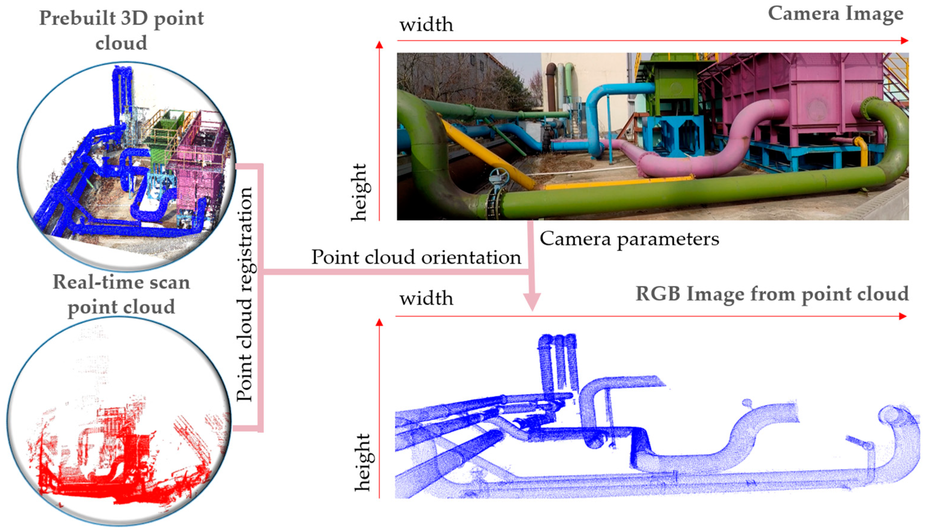
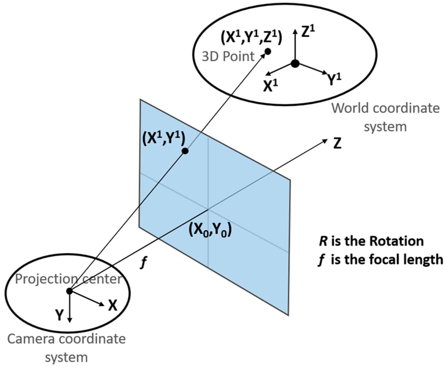
3.2. 3D Point-to-Image Pixel Correspondence

The geo-referenced prebuilt 3D point cloud data generated using the total station were acquired based on the world coordinate system; these were used to generate the corresponding 2D image representation. These points were projected onto a plane defined by the camera parameters. Furthermore, the generated 2D image representation of the 3D point cloud was superimposed over the camera image, as shown in Figure 7.

3.2.1. Sensor Calibration and Initial Alignment of Prebuilt Data

Calibration between the LiDAR sensor and camera is required to accurately align the point cloud information in an image. This is because an image captured using the camera is an RGB image and its characteristics are different from an image created from the point cloud acquired from the LiDAR sensor. Fusion of the camera and LiDAR sensor was recently used in many computer vision applications to enhance performance. Many researchers have proposed methods to calibrate RGB cameras with LiDAR sensors. For our proposed method, we used the calibration approach presented by Martin et al. [33] to calibrate the RGB camera with the LiDAR. The sensor setup in our method includes a Velodyne’s VLP-16 LiDAR sensor and an RGB camera integrated with the MTw XSens IMU [34].
Calibration of the RGB camera with LiDAR was mainly used to fuse different data types, such as images and point clouds, to establish correspondence between pixels in the camera image and points in the LiDAR sensor. A marker-based calibration method provides efficient alignment of the camera and LiDAR data. Geometrical displacement in the data from the two sensors was adjusted with respect to the marker position detected in both sensors.
Orientation of the scanning platform was obtained from the MTw IMU sensor, which outputs 3D orientations using different representations, such as unit quaternions, Euler angles, and a rotation matrix. We have considered a unit quaternion Q m a t output from the IMU sensor for the initial alignment of a prebuilt point cloud and projected the 3D point cloud using camera intrinsic parameters I by using Equation (6).
P p r o j   =   I   ×   P i n p u t   C p a l i g n     =     Q m a t   .   P p r o j
where I = [ 1 0 c x 0 1 c y 0 0 1 ]   × [ f x 0 0 0 f y 0 0 0 1 ] × [ 1 s / f x 0 0 1 0 0 0 1 ] is the known camera intrinsic parameters c x and c y are image center, f x and f y are focal lengths in pixel units and s is the shearing factor, P i n p u t is the input from previous aligned data P t and P p r o j is the projected point cloud. C P a l i g n is the aligned point cloud with respect to scanning platform using IMU sensor.

3.2.2. 2D RGB Image from a 3D Point Cloud

The prebuilt 3D point cloud data obtained from the LiDAR sensor are defined in the world coordinate system. To generate the corresponding RGB image, 3D points were projected onto an image plane defined by the intrinsic camera parameters and LiDAR and camera calibrated extrinsic calibration parameters as described in Equation (7).
P 2 d [ x y 1 ]   =   I   E   P 3 d [ x y z 1 ]
where E   =   [ r 11 r 12 r 13 t x r 21 r 22 r 23 t y r 31 r 32 r 33 t z ] is extrinsic camera & LiDAR calibration matrix, with translation parameters t x , t y and t z , rotational parameters r 11 to r 33 . I is the camera intrinsic parameters, P 3 d is 3D point cloud and P 2 d is the converted 2D image coordinates.
The center of the camera lens is considered to be the origin of the camera coordinate system, as shown in Figure 8. The Z direction is perpendicular to the X Y plane of the camera coordinate system, with the positive direction towards the objects to be imaged. The 3D LiDAR point cloud is projected onto the image plane defined by the camera sensor. The positional difference between the LiDAR and camera is obtained by the parameters t x , t y and t z . These parameters estimated by performing LiDAR and the camera calibration using the calibration method presented in Section 3.2.1.
As shown in Figure 8, the projection origin of the camera coordinate system occurs when the capturing image is defined at the center ( X , Y , f ) . The camera focal length (f), width (w), and height (h) of the generated image were used to define the image plane for the LiDAR point cloud projection. As shown in Figure 9a, the prebuilt 3D point cloud was generated from the LiDAR sensor and projected onto the image plane defined by the camera parameters using Equations (8) and (9).
x = f a 1 ( X X 0 ) + a 2 ( Y Y 0 ) + a 3 ( Z Z 0 ) a 7 ( X X 0 ) + a 8 ( Y Y 0 ) + a 9 ( Z Z 0 )
y = f a 4 ( X X 0 ) + a 5 ( Y Y 0 ) + a 6 ( Z Z 0 ) a 7 ( X X 0 ) + a 8 ( Y Y 0 ) + a 9 ( Z Z 0 )
Here, ( a 1 a 2 a 3 a 4 a 5 a 6 a 7 a 8 a 9 ) = ( 1 0 0 0 cos ω sin ω 0 sin ω cos ω ) ( cos φ 0 sin φ 0 1 0 sin φ 0 cos φ ) ( cos κ sin κ 0 sin κ cos κ 0 0 0 1 ) .

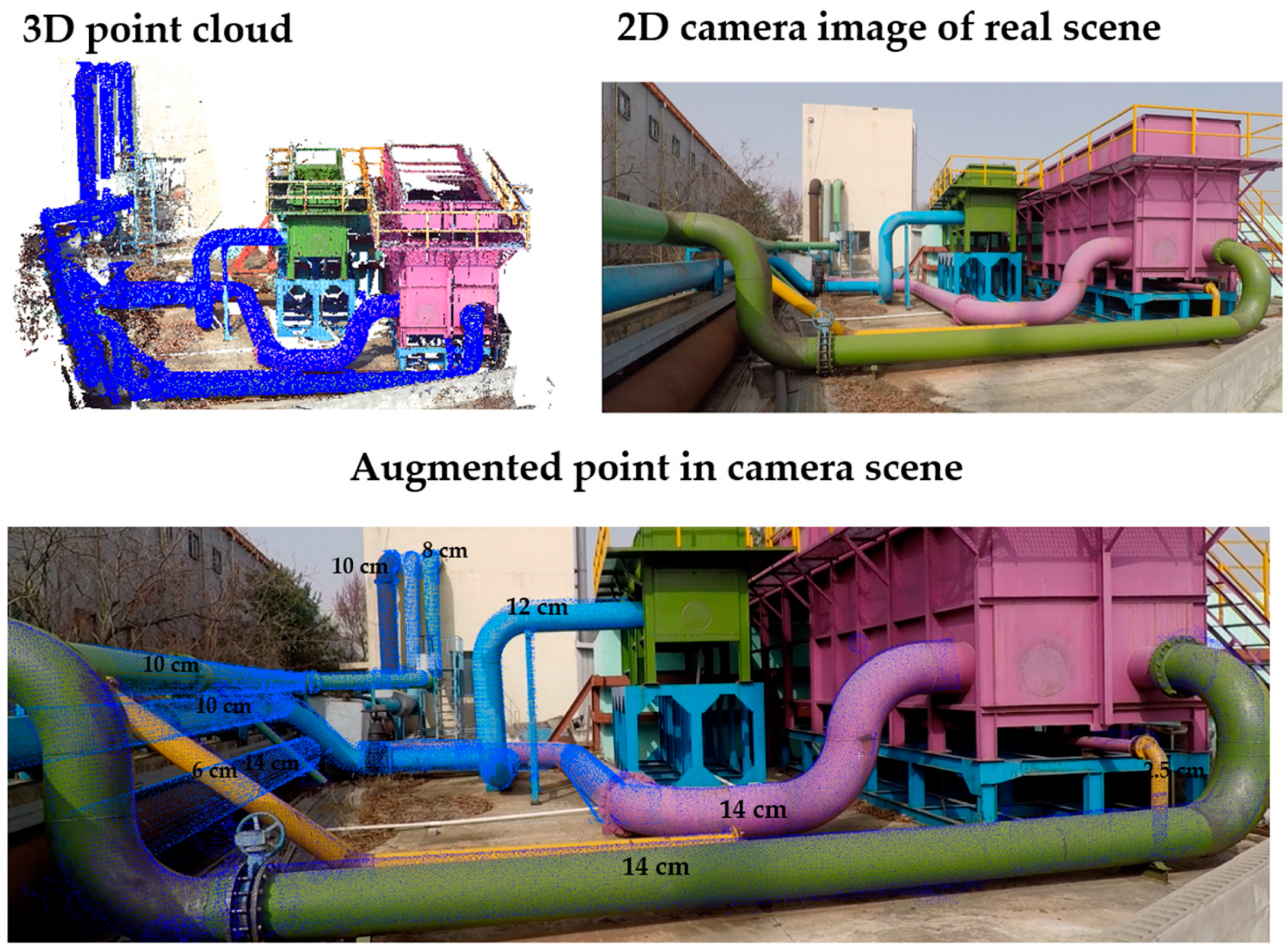
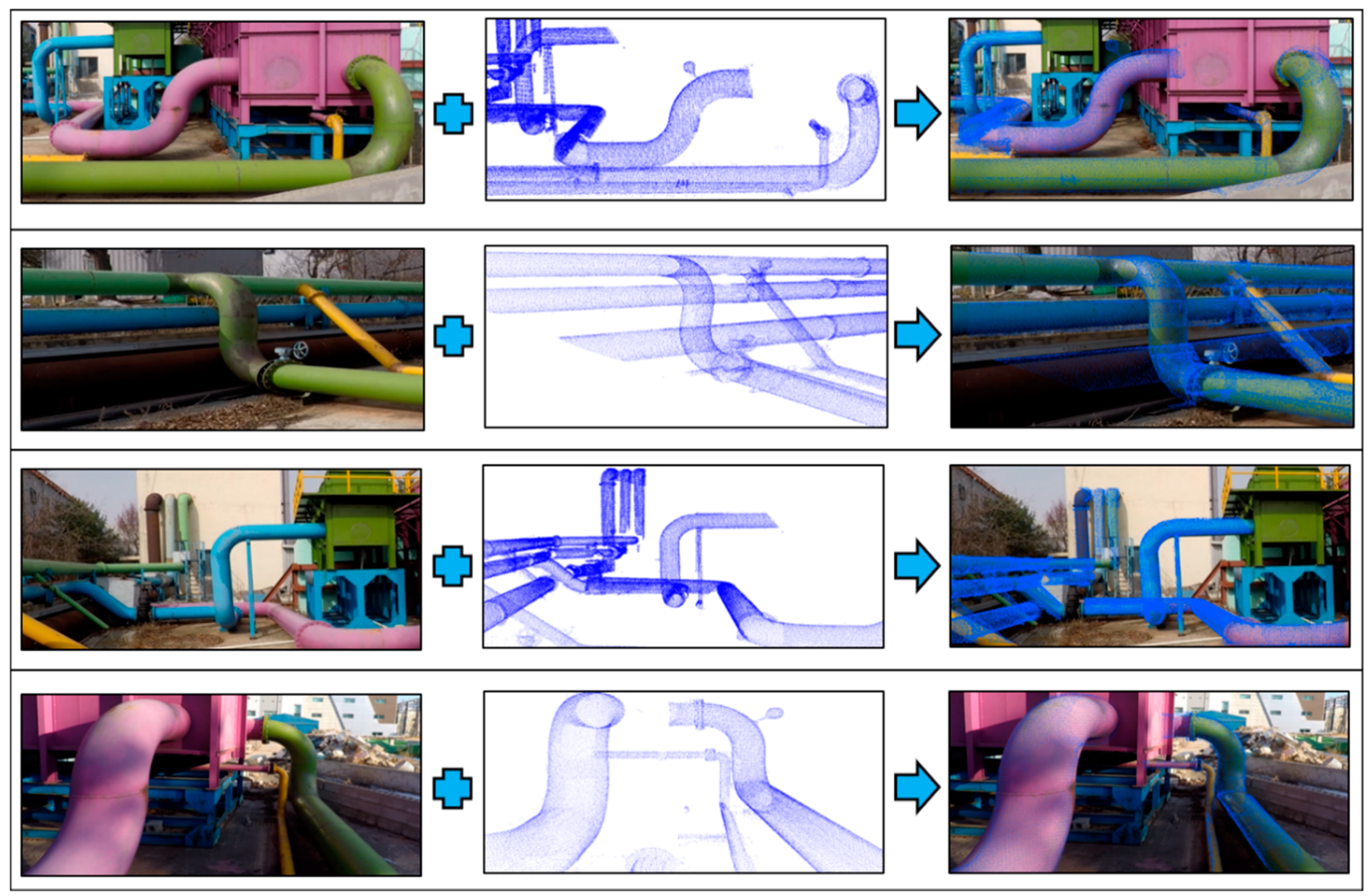
3.2.3. Point Cloud Augmentation in Video

After aligning the prebuilt point cloud according to the real-time scanner view using a 3D point cloud-based registration algorithm, a 2D RGB image of the 3D point cloud was extracted, as described in Section 3.2.2. Furthermore, the extracted point cloud image was aligned onto the camera image, as shown in Figure 10.
The intensity value in the point cloud image was updated to the camera frame using the following Equation (10):
i f   i = 0 i = w j = 0 j = h C I ( i , j ) [ r , g , b ] = I [ r : 0 ,   g : 0 ,   b : 255 ]
Here, w     a n d     h     represent the width and height of the image, respectively.
Then, we replaced the intensity of the F I ( i , j ) t h pixel with the corresponding intensity of the C I ( i , j ) t h pixel, as shown in the equation below. Here, F I   a n d     C I are the camera video frame and point cloud image, respectively.
F I [ r , g , b ] = C I [ r , g , b ]
As shown in Figure 10, the first row represents the frame of the video captured from the camera and image, while the second row represents the RGB image extracted from the prebuilt point cloud. Finally, the point cloud image alignment in the camera image is presented in the third row.

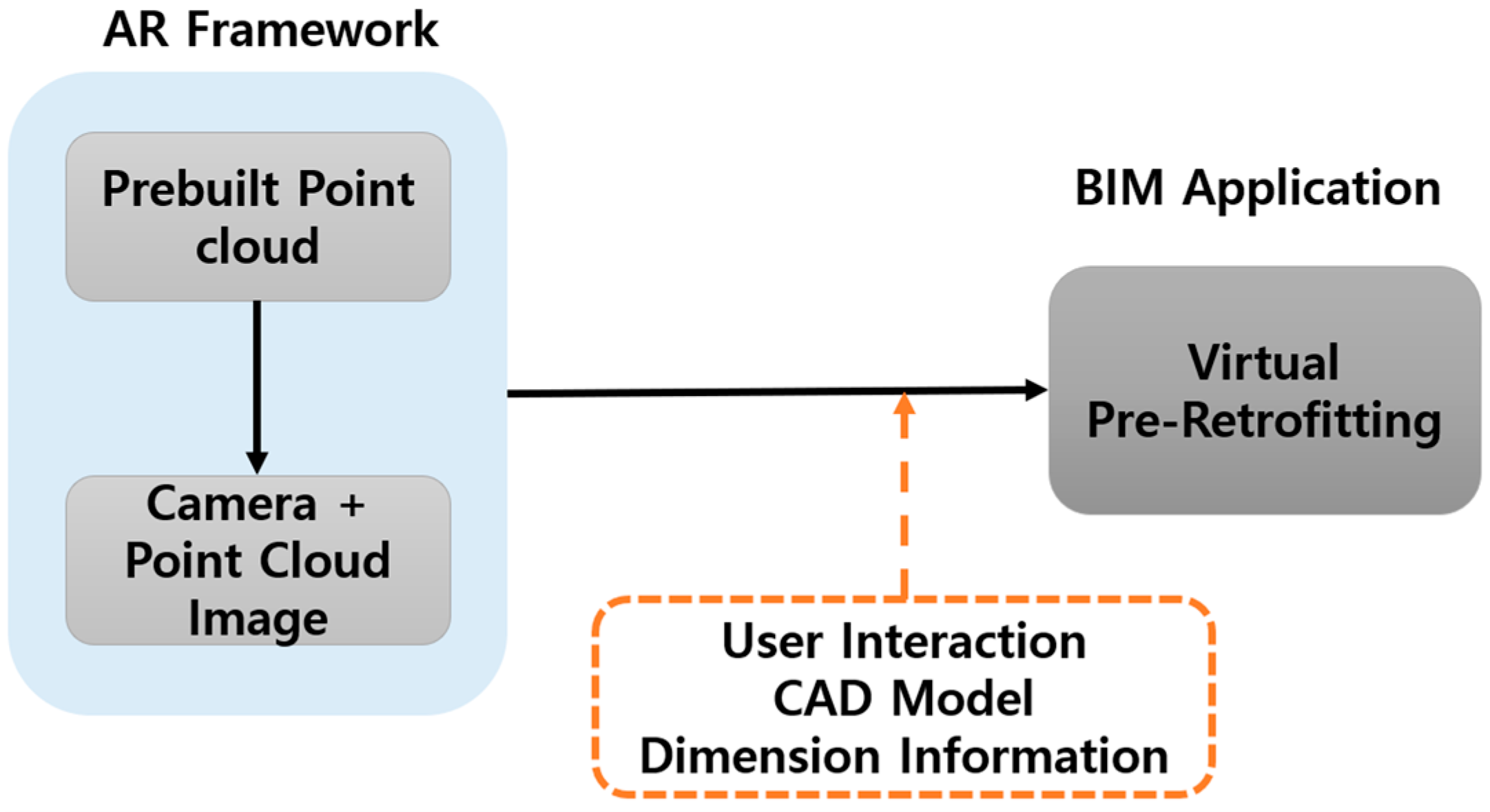
4. Pipeline Retrofitting

The proposed AR framework for the BIM technology enables retrofitting of pipeline plants. The proposed method was used to demonstrate real-world retrofitting of a water supply plant facility at KICT (Korea Institute of Construction Technology), as shown in Figure 11. Technological advancements in the equipment used in water supply plant facilities force owners to periodically retrofit treatment plants. There are some essential considerations that need to be kept in mind to ensure that the modification or extension of existing water plants utilizes fewer resources and is more cost effective. Retrofitting existing plants occurs for many reasons, but common reasons include pipeline reinforcement upgrades, the need to increase water requirements, and the integration of new technologies into existing facilities.

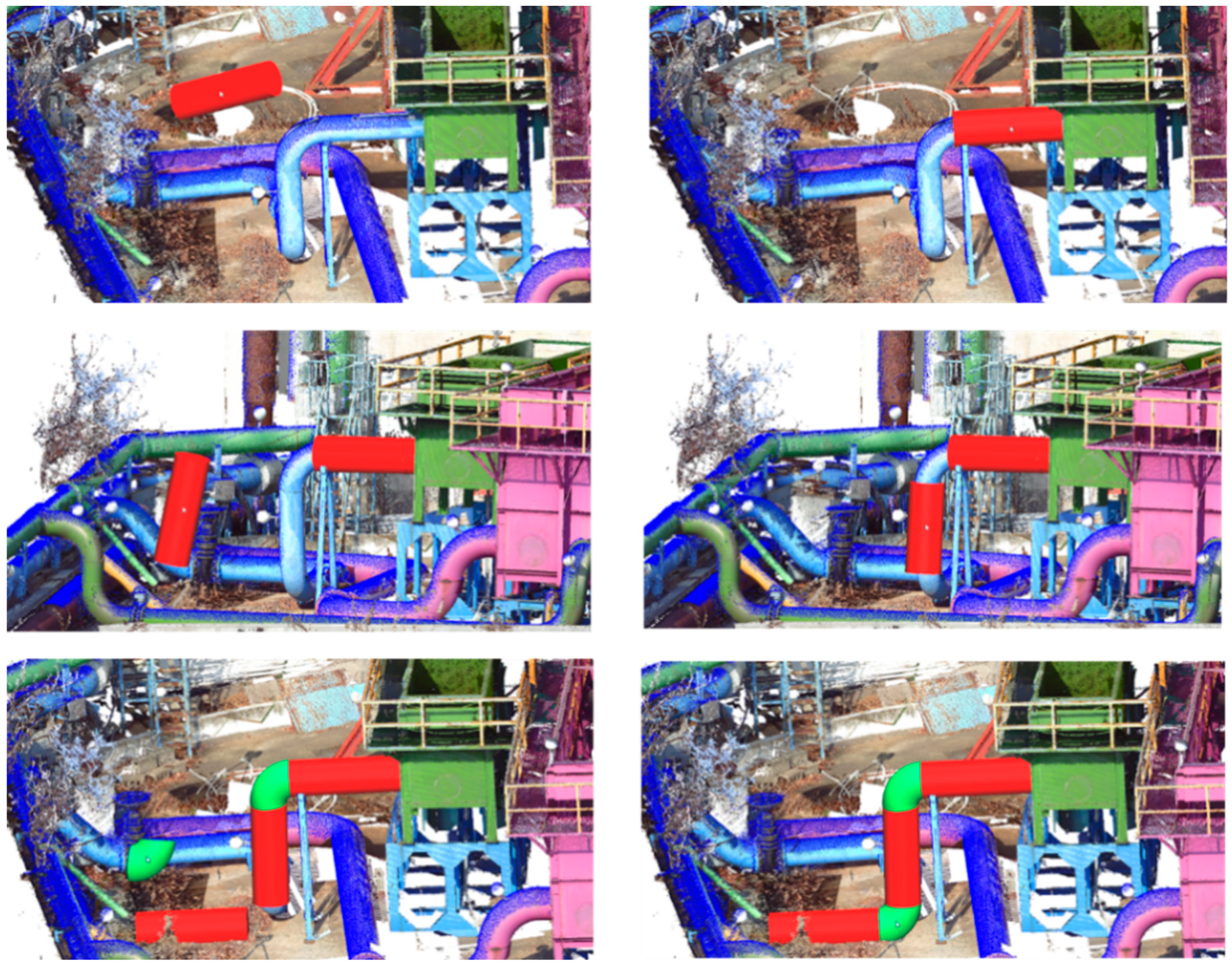
Virtual Pre-Retrofitting

As AR systems become more promising, tools for complex structure monitoring tasks in construction engineering, their application increasingly benefits onsite engineers by allowing for virtual retrofitting processes. Engineers can efficiently investigate the effects of rectifying defects, retrofitting or replacing defective parts, and extending existing portions of the plant. Also, virtual retrofitting allows for the feasibility of an overall rehabilitation process to be analyzed before any actual retrofitting, thereby reducing the possibility of uncertain challenges during the process.
Virtual pre-retrofitting is a process that provides an affordable computational platform for data analysis and integration to support decision-making in retrofitting applications. Figure 12 provides an overview of the retrofitting process. In this work, retrofitting of a pipeline plant at a water treatment site was considered as a special scenario for experimental evaluation. The virtual retrofit model presented in this article gathered and integrated pipeline data information utilizing LiDAR and camera sensors. The virtual model of the pipeline was acquired using the LiDAR sensor and a real environment scene obtained using a camera.
The aim of pipeline virtual pre-retrofitting is to allow users to evaluate tasks, such as pipeline geometry inspection, in real-time by using dimensional information (shown in Figure 13) presented in our previous work [35]. Additionally, engineers can use this method to modify existing pipeline structures and extend the pipeline with additional equipment in a virtual environment. As show in Figure 14, the proposed AR framework can be integrated into the pipeline virtual retrofitting process to modify existing equipment and add new parts to an existing plant.

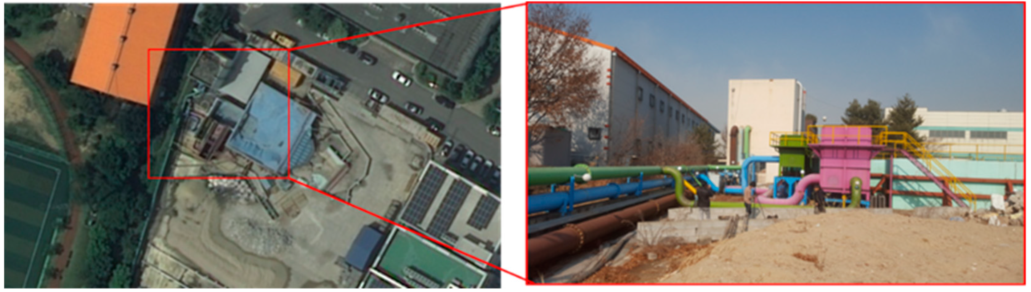
5. Experimental Verification

To verify the proposed AR framework for pipeline retrofitting applications in real-time, tests and statistical analyses were conducted separately for each of the core processes involved in the proposed system. First, the robustness of the real-time registration process was verified by comparing existing registration methods. Next, the efficiency of the retrofitting process was evaluated by considering water treatment plant pipeline data.

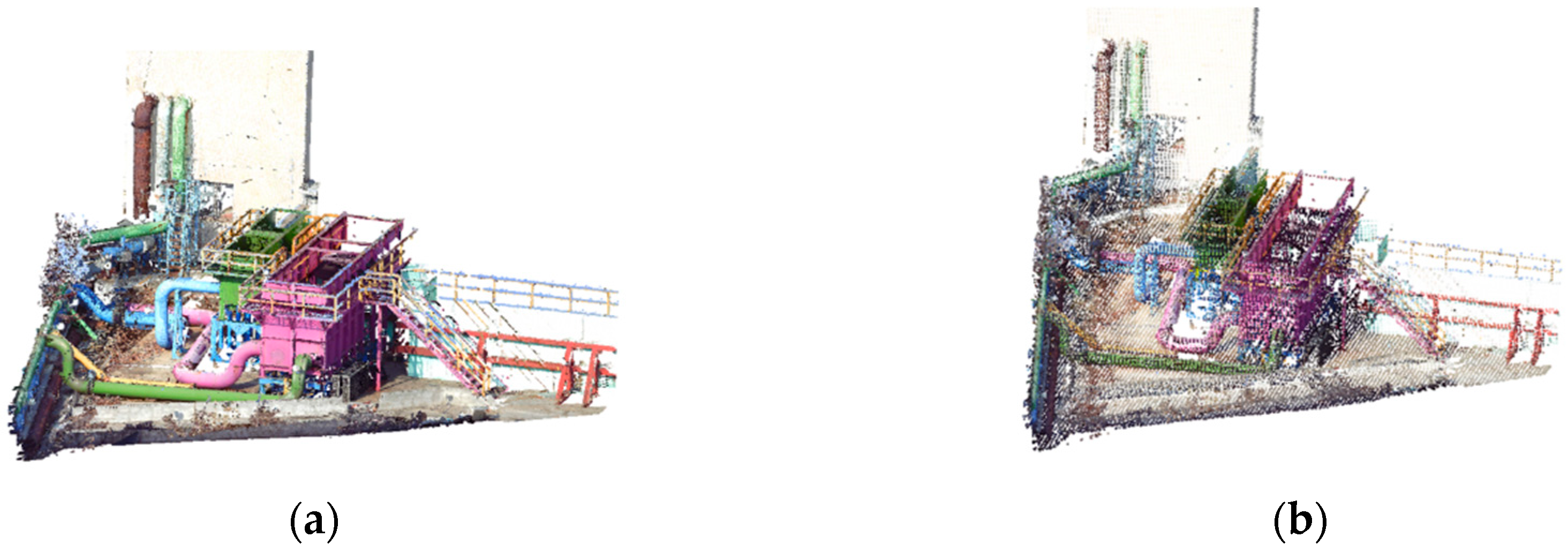
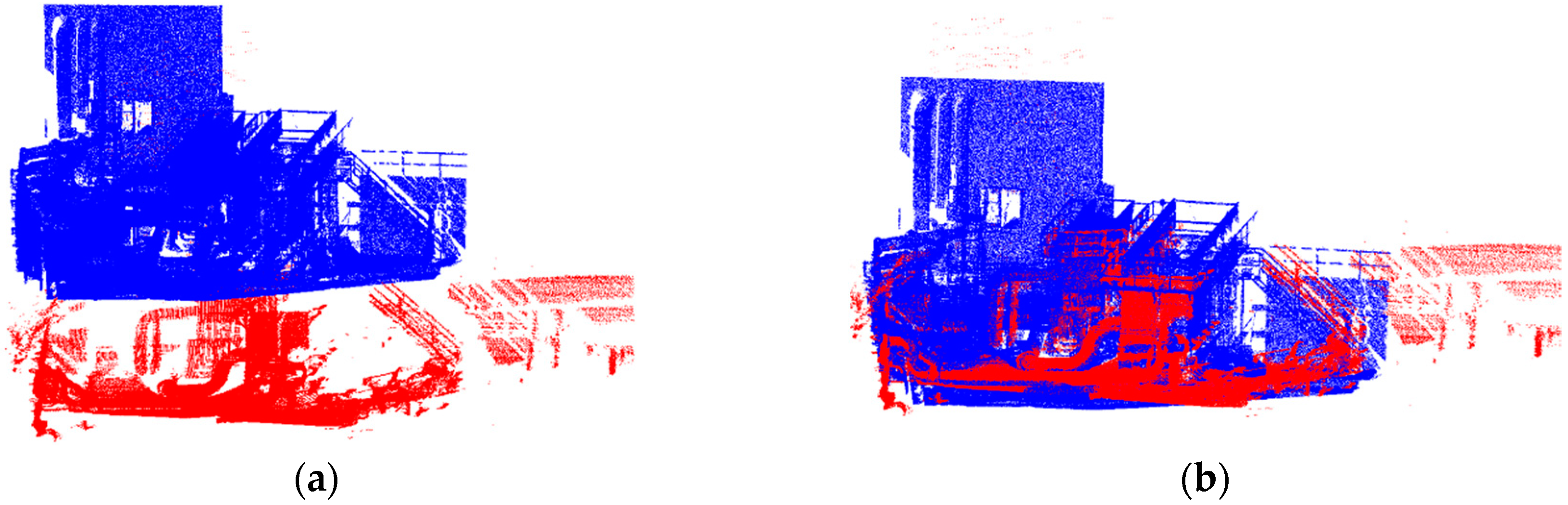
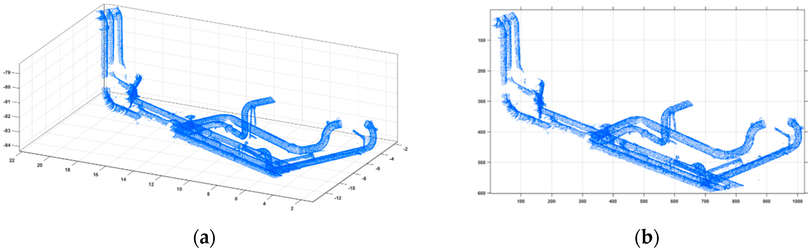
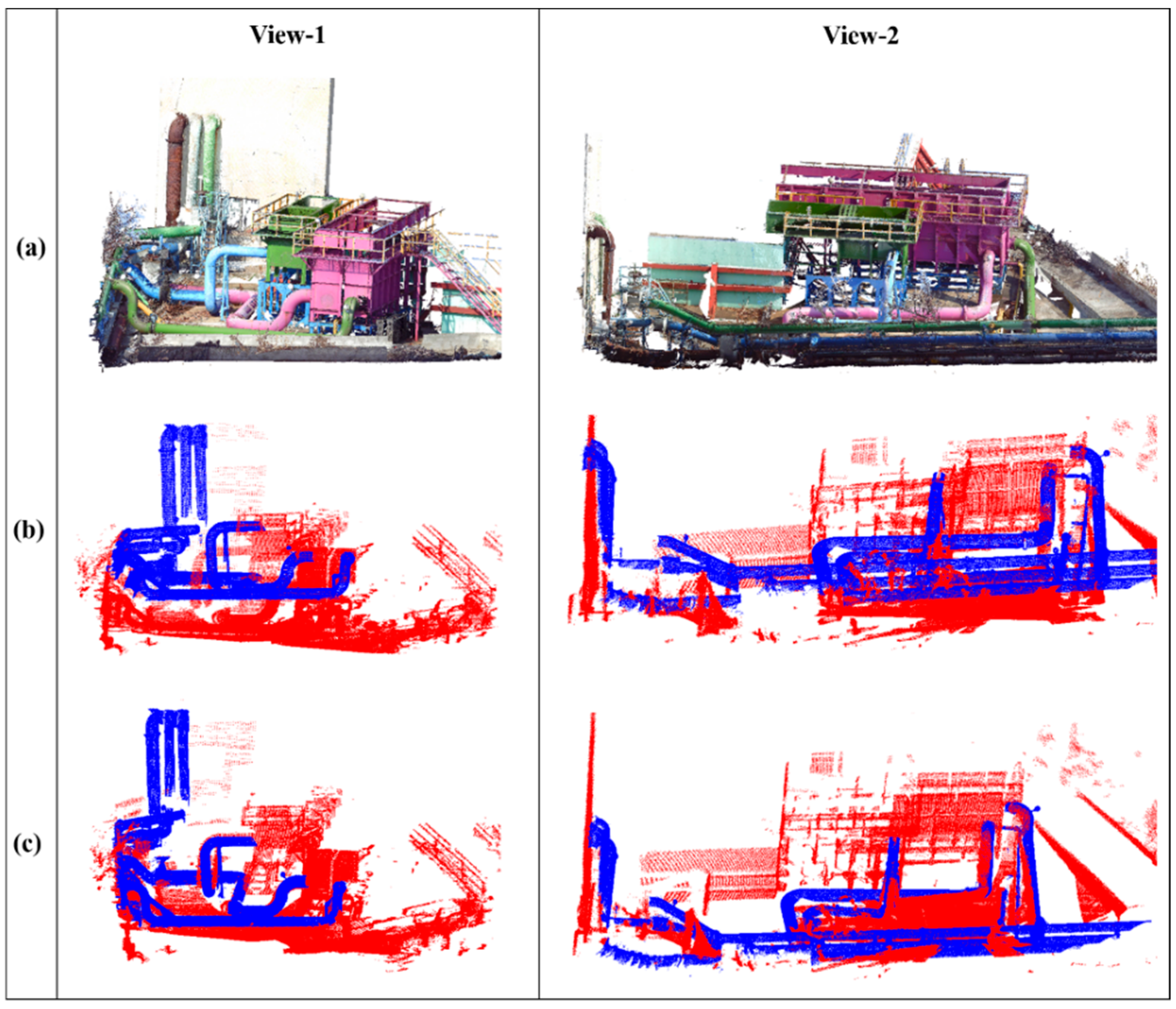
5.1. 3D Point Cloud-Based Registration

To clarify the behavior of the alignment approach, the proposed method was evaluated by considering the time efficiency and its precision score. For validation, the point cloud with the original prebuilt data and optimal prebuilt data were compared utilizing G-ICP. Two different experimental real-time LiDAR scan point cloud data (in red color) sets were used for alignment of prebuilt data (in blue color), as shown in Figure 15 (i.e., View-1 and View-2). Table 1 shows the validation results for achieving final alignment of the prebuilt point cloud.
The time efficiency (which decreased by more than 80%) and the precision score (Alignment) of (which improved by ~10%) of the optimal prebuilt data are better than those of the directly used, original prebuilt data for our alignment method. The alignment of the original prebuilt point cloud was achieved with fewer iterations, whereas the number of optimal point cloud iterations increased by an average of three iterations.

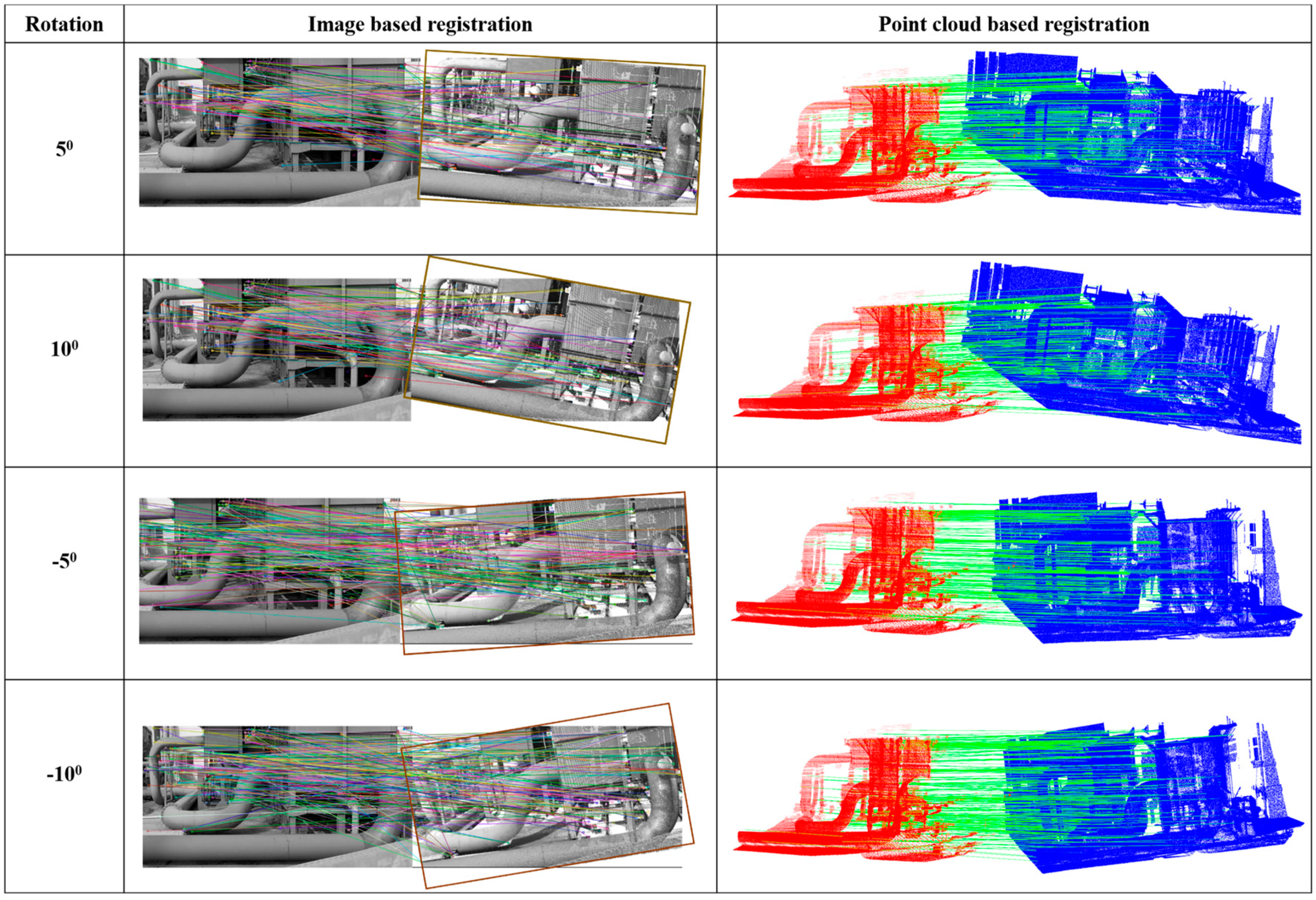
5.2. Comparison with Image-Based Registration

Experiments were conducted for a water treatment pipeline plant to verify the efficiency of the image-based registration with 3D point cloud registration for the AR framework. Therein, four different views of the point cloud image, each with a different orientation, were considered to verify the accuracy of the image-based registration method, and the obtained results were compared with the point cloud-based registration method results with similarly oriented views of the prebuilt point cloud. In Figure 16, the left-side column shows four different views of the point cloud image with respect to the camera image; the detection of key points in the 3D point cloud registration is also shown.
In Table 2 and Table 3, the computational run time requirement of the proposed point cloud-based registration and image-based registration method were analyzed. Based on this analysis, we can draw the conclusion that the time requirement of the point cloud-based registration method is better than image-based registration.
The results obtained from the proposed point cloud registration method were compared with those of a typical image-based registration method to verify the accuracy of the proposed method. In Table 4, the orientation estimated from the two-registration approach was compared with predefined orientation scenarios. An experiment was conducted by using the input point cloud and image with predefined orientations of 5° and 10° in a clockwise direction as well as 5° and 10° in an anti-clockwise direction. The orientations estimated from the four different scenarios using these two approaches are presented in Table 4; this shows that our method estimates almost the same orientation as the predefined orientation, indicating that this procedure is reliable.

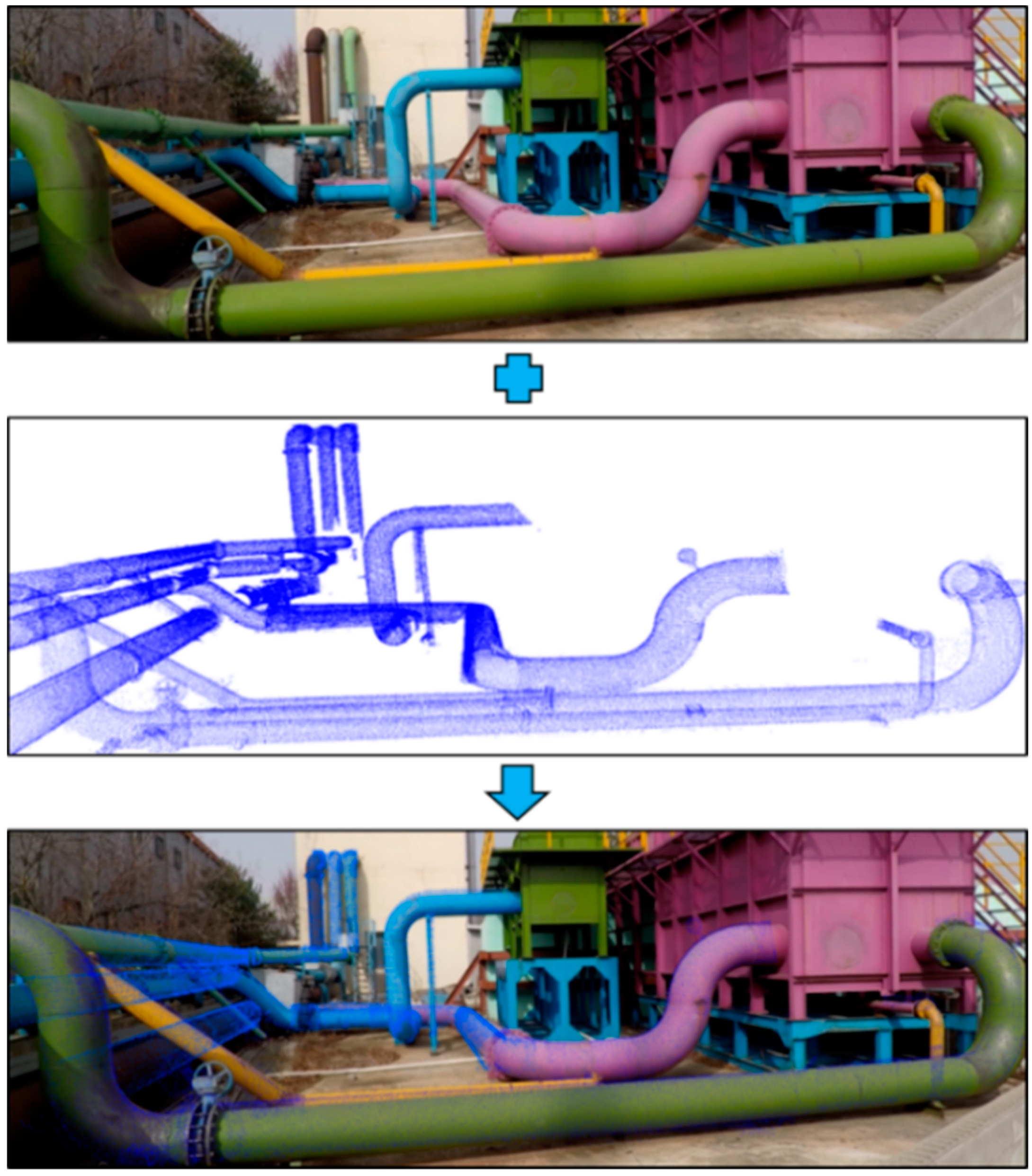
5.3. Point Cloud Alignment in the Video Frames

The results of the alignment of point clouds in the images extracted from video are shown in Figure 17. The first column in the figure contains frames of the real environment scene extracted from the video at 30 FPS, while the second column presents an RGB image of a 3D point cloud with a view corresponding to the camera image. The third column in the figure shows the final alignment in real-time. Computational time for alignment of points on each camera frame is 60 ms. This provides smooth visualizing experience to the user without any delay. Average time requirement for alignment varies depending on the Field of View (FOV) and resolution of camera. In this work, Samsung USB camera (Model: SPC-A1200MB) with 60° horizontal and 45° vertical FOV, and 640 × 480 resolution image is used.

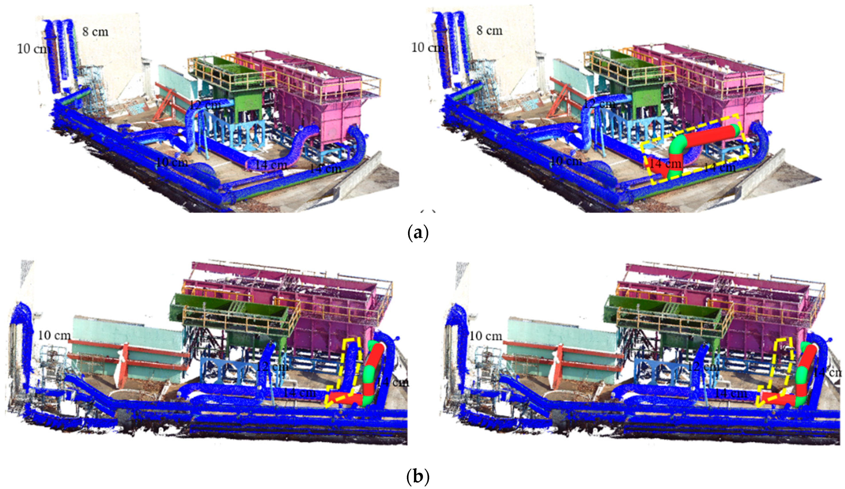
5.4. Pipeline Virtual Retrofitting

The AR framework proposed in this paper is efficiently integrated with the pipeline retrofitting process. Since the proposed AR framework utilizes a 2D camera for actual scene acquisition, user interactions during the virtual retrofitting process with the 2D data are difficult and unnatural. Hence, the virtual retrofitting process was carried out in the 3D environment with the prebuilt point cloud. User modifications performed on the prebuilt cloud in the 3D environment were regularly updated onto the 2D camera scene. Figure 18 shows the experimental results of the proposed AR framework applied to pipeline retrofitting.

6. Conclusions and Future Work

This paper proposes a method for an augmented reality framework for pipeline pre-retrofitting in BIM engineering. The method presented in this study utilizes prebuilt 3D point cloud data and real-time 3D point cloud data generated from a LiDAR sensor along with a real environment scene captured by a 2D camera. Our method integrates RGB images extracted from the 3D prebuilt point cloud with frames of a video in real-time, which involves alignment of prebuilt point cloud data from the user viewpoint and establishing 3D point clouds in the camera image. This approach introduces the proposed AR framework, which can be utilized in industrial pipeline pre-retrofitting.
Experimental verification was conducted at water treatment plant to demonstrate the significance of the proposed AR framework for use in retrofitting applications. The resulting run time differences for four scenarios, as well as the orientation estimation results of two approaches (i.e., 2D image-based registration and 3D point cloud registration), show that 3D point cloud-based alignment is optimal for the AR framework.
This work can continue in several directions. Mainly, future work will involve integrating the localization of a scanning platform to enhance the system’s real-time capabilities. Also, efficient interaction techniques can be developed to benefit operators in BIM applications.

Author Contributions

Conceptualization and methodology: G.A.K., A.K.P. and Y.H.C.; software and validation: G.A.K. and A.K.P.; formal analysis and investigation: G.A.K., A.K.P., T.W.K. and Y.H.C.; resources and data curation: G.A.K., A.K.P. and T.W.K.; writing—original draft preparation and writing—review and editing: G.A.K. and A.K.P.; visualization: G.A.K. and A.K.P.; supervision, project administration, and funding acquisition: Y.H.C.

Funding

This work was supported by the National Research Foundation (NRF) grant (2016R1D1A1B03930795) funded by the Korea government (MEST) and the Ministry of Science, ICT of Korea, under the Software Star Lab. program (IITP-2018-0-00599) supervised by the Institute for Information and communications Technology Promotion.

Conflicts of Interest

The authors declare no conflict of interest.

References

  1. Bui, N.; Merschbrock, C.; Munkvold, B.E. A review of Building Information Modelling for construction in developing countries. Procedia Eng. 2016, 164, 487–494. [Google Scholar] [CrossRef]
  2. Amiri, R.; Sardroud, J.M.; de Soto, B.G. BIM-based applications of metaheuristic algorithms to support the decision-making process: Uses in the planning of construction site layout. Procedia Eng. 2017, 196, 558–564. [Google Scholar] [CrossRef]
  3. Sanhudo, L.; Ramos, N.M.; Martins, J.P.; Almeida, R.M.; Barreira, E.; Simões, M.L.; Cardoso, V. Building information modeling for energy retrofitting–A review. Renew. Sustain. Energy Rev. 2018, 89, 249–260. [Google Scholar] [CrossRef]
  4. Takim, R.; Harris, M.; Nawawi, A.H. Building Information Modeling (BIM): A new paradigm for quality of life within Architectural, Engineering and Construction (AEC) industry. Procedia Soc. Behav. Sci. 2013, 101, 23–32. [Google Scholar] [CrossRef]
  5. Zhu, Z.; Donia, S. Spatial and visual data fusion for capturing, retrieval, and modeling of as-built building geometry and features. Vis. Eng. 2013, 1, 10. [Google Scholar] [CrossRef] [Green Version]
  6. Wang, X.; Truijens, M.; Hou, L.; Wang, Y.; Zhou, Y. Integrating Augmented Reality with Building Information Modeling: Onsite construction process controlling for liquefied natural gas industry. Autom. Constr. 2014, 40, 96–105. [Google Scholar] [CrossRef]
  7. Park, J.; Kim, B.; Kim, C.; Kim, H. 3D/4D CAD applicability for life-cycle facility management. J. Comput. Civ. Eng. 2011, 25, 129–138. [Google Scholar] [CrossRef]
  8. Chantawit, D.; Hadikusumo, B.H.; Charoenngam, C.; Rowlinson, S. 4DCAD-Safety: Visualizing project scheduling and safety planning. Constr. Innov. 2005, 5, 99–114. [Google Scholar] [CrossRef]
  9. Li, X.; Yi, W.; Chi, H.L.; Wang, X.; Chan, A.P. A critical review of virtual and augmented reality (VR/AR) applications in construction safety. Autom. Constr. 2018, 86, 150–162. [Google Scholar] [CrossRef]
  10. Khalek, I.A.; Chalhoub, J.M.; Ayer, S.K. Augmented reality for identifying maintainability concerns during design. Adv. Civ. Eng. 2019. [Google Scholar] [CrossRef]
  11. Bae, H.; Golparvar-Fard, M.; White, J. High-precision vision-based mobile augmented reality system for context-aware architectural, engineering, construction and facility management (AEC/FM) applications. Vis. Eng. 2013, 1, 3. [Google Scholar] [CrossRef] [Green Version]
  12. Toro, C.; Sanín, C.; Vaquero, J.; Posada, J.; Szczerbicki, E. Knowledge based industrial maintenance using portable devices and augmented reality. In Proceedings of the International Conference on Knowledge-Based and Intelligent Information and Engineering Systems, Vietri sul Mare, Italy, 12–14 September 2007; pp. 295–302. [Google Scholar] [CrossRef]
  13. Wang, X.; Love, P.E.; Kim, M.J.; Park, C.S.; Sing, C.P.; Hou, L. A conceptual framework for integrating building information modeling with augmented reality. Autom. Constr. 2013, 34, 37–44. [Google Scholar] [CrossRef]
  14. Chu, M.; Matthews, J.; Love, P.E. Integrating mobile Building Information Modelling and Augmented Reality systems: An experimental study. Autom. Constr. 2018, 85, 305–316. [Google Scholar] [CrossRef]
  15. Doil, F.; Schreiber, W.; Alt, T.; Patron, C. Augmented reality for manufacturing planning. In Proceedings of the Workshop on Virtual Environments 2003, Zurich, Switzerland, 22–23 May 2003; pp. 71–76. [Google Scholar] [CrossRef]
  16. Tang, A.; Owen, C.; Biocca, F.; Mou, W. Comparative effectiveness of augmented reality in object assembly. In Proceedings of the SIGCHI conference on Human factors in computing systems 2003, Ft. Lauderdale, FL, USA, 5–10 April 2003; pp. 73–80. [Google Scholar] [CrossRef]
  17. Sanz, A.; González, I.; Castejón, A.J.; Casado, J.L. Using virtual reality in the teaching of manufacturing processes with material removal in CNC machine-tools. In Materials Science Forum; Trans Tech Publications Ltd.: Zurich, Switzerland, 2011; Volume 692, pp. 112–119. [Google Scholar] [CrossRef]
  18. Tabrizi, A.; Sanguinetti, P. Literature review of augmented reality application in the architecture, engineering, and construction industry with relation to building information. In Advanced Methodologies and Technologies in Engineering and Environmental Science; IGI Global: Hershey, PA, USA, 2019; pp. 61–73. [Google Scholar]
  19. De Freitas, M.R.; Ruschel, R.C. Augmented reality supporting building assesment in terms of retrofit detection. In Proceedings of the CIB W078 International Conference, Beijing, China, 9–12 October 2013; pp. 1–10. [Google Scholar]
  20. Gupta, S.; Lohani, B. Augmented reality system using lidar point cloud data for displaying dimensional information of objects on mobile phones. ISPRS Ann. Photogramm. Remote Sens. Spat. Inf. Sci. 2014, 2, 153. [Google Scholar] [CrossRef]
  21. Tam, G.K.; Cheng, Z.Q.; Lai, Y.K.; Langbein, F.C.; Liu, Y.; Marshall, D.; Martin, R.R.; Sun, X.F.; Rosin, P.L. Registration of 3D point clouds and meshes: A survey from rigid to nonrigid. IEEE Trans. Vis. Comput. Graph. 2013, 19, 1199–1217. [Google Scholar] [CrossRef]
  22. Diao, P.H.; Shih, N.J. BIM-based AR Maintenance System (BARMS) as an intelligent instruction platform for complex plumbing facilities. Appl. Sci. 2019, 9, 1592. [Google Scholar] [CrossRef]
  23. Besl, P.J.; McKay, N.D. A method for registration of 3-D shapes. IEEE Trans. Pattern Anal. Mach. Intell. 1992, 14, 239–256. [Google Scholar] [CrossRef]
  24. Chen, Y.; Medioni, G. Object modelling by registration of multiple range images. Image Vis. Comput. 1992, 10, 145–155. [Google Scholar] [CrossRef]
  25. Low, K.L. Linear Least-Squares Optimization for Point-To-Plane ICP Surface Registration; Technical Report TR04-004; University of North Carolina: Chapel Hill, NC, USA, 2004. [Google Scholar]
  26. Alshawa, M. ICL: Iterative closest line A novel point cloud registration algorithm based on linear features. Ekscentar 2007, 10, 53–59. [Google Scholar]
  27. Segal, A.; Haehnel, D.; Thrun, S. Generalized-ICP. In Proceedings of the Robotics: Science and Systems, Seattle, WA, USA, 28 June–1 July 2009; p. 435. [Google Scholar]
  28. Patil, A.K.; Kumar, G.A.; Kim, T.H.; Chai, Y.H. Hybrid approach for alignment of a pre-processed three-dimensional point cloud, video, and CAD model using partial point cloud in retrofitting applications. Int. J. Distrib. Sens. Netw. 2018, 14, 1550147718766452. [Google Scholar] [CrossRef]
  29. Trimble. Available online: http://trl.trimble.com/docushare/dsweb/Get/Document-628869/022504-122_Trimble_TX5_DS_1012_LR.pdf (accessed on 7 October 2019).
  30. Velodyne LiDAR. Available online: http://velodynelidar.com/vlp-16.html (accessed on 7 October 2019).
  31. Vitter, J.S. Faster methods for random sampling. Commun. ACM 1984, 27, 703–718. [Google Scholar] [CrossRef] [Green Version]
  32. Holz, D.; Ichim, A.E.; Tombari, F.; Rusu, R.B.; Behnke, S. Registration with the point cloud library: A modular framework for aligning in 3-d. IEEE Robot. Autom. Mag. 2015, 22, 110–124. [Google Scholar] [CrossRef]
  33. Vel’as, M.; Španěl, M.; Materna, Z.; Herout, A. Calibration of RGB camera with velodyne lidar. In Proceedings of the 22nd International Conference on Computer Graphics, Visualization and Computer Vision, Plzen, Czech Republic, 2–5 Jun 2014. [Google Scholar]
  34. MTw Awinda. Available online: https://www.xsens.com/products/mtw-awinda/ (accessed on 7 October 2019).
  35. Kumar, G.A.; Patil, A.K.; Patil, R.; Park, S.S.; Chai, Y.H. A LiDAR and IMU integrated indoor navigation system for UAVs and its application in real-time pipeline classification. Sensors 2017, 17, 1268. [Google Scholar] [CrossRef] [PubMed]
Figure 1. Augmented reality in building information modelling (BIM) engineering.
Symmetry 11 01325 g001
Figure 2. Overview of the proposed system.
Symmetry 11 01325 g002
Figure 3. (a) Prebuilt 3D point cloud, (b) prebuilt point cloud with segmented pipeline, and (c) real-time scan point cloud.
Symmetry 11 01325 g003
Figure 4. Block diagram depicting the optimal alignment process.
Symmetry 11 01325 g004
Figure 5. (a) Prebuilt point cloud data set and (b) optimal subsampled point cloud.
Symmetry 11 01325 g005
Figure 6. Alignment results: (a) before alignment and (b) after alignment.
Symmetry 11 01325 g006
Figure 7. Red-Green-Blue (RGB) image extraction from the prebuilt point cloud.
Symmetry 11 01325 g007
Figure 8. The 3D point cloud projection on the image plane was defined by the camera’s coordinate system.
Symmetry 11 01325 g008
Figure 9. A 3D point cloud to 2D image plane projection: (a) segmented 3D point cloud of the pipeline and (b) 2D image representation of the 3D point cloud.
Symmetry 11 01325 g009
Figure 10. Point cloud image alignment on the camera image.
Symmetry 11 01325 g010
Figure 11. Point cloud image alignment on the camera image.
Symmetry 11 01325 g011
Figure 12. Augmented reality (AR) framework in retrofitting application.
Symmetry 11 01325 g012
Figure 13. Pipe geometry (dimension) inspection in real-time, (a) 14 cm cylinder, (b) 8 cm cylinder.
Symmetry 11 01325 g013
Figure 14. Different scenarios in the retrofitting process, (a) insertion, (b) deletion.
Symmetry 11 01325 g014
Figure 15. Prebuilt point cloud alignment results: (a) original prebuilt point cloud view, (b) before alignment, and (c) after alignment.
Symmetry 11 01325 g015
Figure 16. Orientation estimation using the point cloud registration method.
Symmetry 11 01325 g016
Figure 17. Point cloud alignment in the camera image.
Symmetry 11 01325 g017
Figure 18. Pipeline retrofitting of straight pipes and elbow.
Symmetry 11 01325 g018
Table 1. Time efficiency analysis for the prebuilt point cloud.
MethodIterationsRun Time (s)Alignment Score 1
View-1View-2View-1View-2View-1View-2
GICP651.040.6300.0230.037
OGICP880.180.0970.0210.032
1 Alignment Score is the squared Euclidean distance between two sets of correspondence (Key points as shown in Figure 4).
Table 2. Run time and rotation accuracy for 2D image-based registration for scenarios shown in Figure 16.
ScenarioRun Time (s)Translation/mmRotation/°
a1.913−0.0120.0400.000.0000.000−1.344
b2.0360.1450.1960.000.0000.000−1.414
c1.9960.0450.0290.000.0000.000−0.925
d2.0350.1050.3290.000.0000.000−1.098
Table 3. Run time and rotation accuracy for 3D point cloud-based registration for scenarios shown in Figure 16.
ScenarioRun Time (s)Translation/mmRotation/°
a0.189−0.0450.3290.3240.0550.057−0.177
b0.189−0.0640.3530.3210.0410.068−0.337
c0.153−0.0820.3050.3230.0740.0180.382
d0.183−0.0390.3190.3240.078−0.0170.812
Table 4. Orientation accuracy comparison between the image and point cloud registration methods for scenarios shown in Figure 16.
ScenarioActual Orientation (°)Image Registration (°)Point Cloud Registration (°)
a+56.3444.956
b+1011.4149.871
c−5−5.925−4.866
d−10−11.098−9.789

