Article

Effect of Voids Behind Lining on the Failure Behavior of Symmetrical Double-Arch Tunnels

1
School of Civil Engineering, Inner Mongolia University of Science and Technology, Baotou 014000, China
2
Key Laboratory of Urban Underground Engineering of Ministry of Education, Beijing Jiaotong University, Beijing 100044, China
3
School of Civil Engineering, Beijing Jiaotong University, Beijing 100044, China
*
Author to whom correspondence should be addressed.
Symmetry 2019, 11(10), 1321; https://doi.org/10.3390/sym11101321
Submission received: 17 September 2019 / Revised: 15 October 2019 / Accepted: 17 October 2019 / Published: 21 October 2019

Abstract

:
The presence of voids behind lining seriously affects the safety of the symmetrical double-arch tunnels during service life. It is essential to find out the impact of voids on tunnel safety due to the increasing demand for the construction and maintenance of symmetrical double-arch tunnels. Model tests and numerical analyses were conducted in this research. The results attained were explored including earth pressure, internal force, and lining failure. Results reveal that the presence of voids has a large influence on the internal force in the lining of symmetrical double-arch tunnels, generally in the form of asymmetrical failure patterns of the lining. The failure patterns of the lining are greatly influenced by the size and location of voids with respect to the symmetrical double-arch tunnel circumference. Significant changes in the lining internal forces were found at the areas in the close vicinity of the void whereas a few changes were found at the bottom of the sidewall, the invert, and the central wall far away from the void. The propagation laws of lining cracks of asymmetrical double-arch tunnels are more complicated than symmetrical tunnels with a void behind the central wall. The location of the initial cracking of symmetrical and asymmetrical double-arch tunnels is the same, while the lining failure of the large-section tunnel is the most complicated.

1. Introduction

In recent years, the safety of tunnel construction, especially the stability of the tunnel face, has been a research hotspot in the field of tunnel engineering [1,2,3,4]. However, the problem of the defects during the service life of a tunnel has become increasingly outstanding and aroused attention. At present, China is one of the countries in the world that has a large number of highway double-arch tunnels. Due to the special tunnel linings and complicated construction of double-arch tunnels, most of the double-arch tunnels often built in the soft ground generally experienced a loss of soil support behind the tunnel lining around the vault or the central wall according to the non-destructive inspection results [5]. The presence of voids behind lining can lead to many kinds of problems, such as cracking and water leakage, which seriously affects the safety of the double-arch tunnel lining during service life [6]. Thus, it is essential to find out the impact of the defects on the safety of the double-arch tunnels due to the increasing demand for double-arch tunnel maintenance. The introduction of voids behind the lining causes the re-distribution of the earth pressure acting on the lining and, consequently, changes the internal forces in the lining, which leads to the excessive deformation, even cracking, directly affecting the operation of symmetrical or asymmetrical double-arch tunnels, and resulting in huge economic losses and bad social influence [7].
Most studies on the effects of local voids or contact loss between the lining and the soils on a single tunnel have been presented in terms of field investigation [8], theoretical analysis [9], model tests [10], and numerical analysis [11]. Voids can induce the concentrated load to the double-arch tunnel lining and loosening of the soils, with associated shortage of carrying capacity and even damage. Some researchers have been devoted to examining the effect of voids around the double-arch tunnel lining on structural performance. Li et al. [12] investigated the mechanical responses of the lining and the ground at different construction stages of the double-arch tunnel with no void behind the lining. He et al. [13] presented the distribution of internal forces in the lining of an asymmetrical double-arch tunnel without voids by a series of experimental studies. Min et al. [14] concluded a simulation analysis using the extended finite element method to analyze the crack propagation of the double-arch tunnel lining with a void located at the central wall. According to the current research, limited literature exists about the response of the symmetrical double-arch tunnel to voids at different locations. In addition, less knowledge is available about the differences between symmetrical double-arch tunnels and other types of tunnels with voids behind the lining.
The objective of the study is to examine the effect of voids developed around the symmetrical double-arch tunnels on the failure behavior of the symmetrical double-arch tunnel lining. Two model tests and a series of simulation analyses are conducted to investigate the progressive failure process of the symmetrical double-arch tunnel lining with voids introduced at different locations. The role of void size is also investigated. The study provides insight into the internal forces in the lining of the symmetrical double-arch tunnels and presents an analysis of the effect of voids behind the lining on the mechanical behavior of the symmetrical double-arch tunnels. The discussion is also conducted to determine the similar and different points of the lining failure between the symmetrical double-arch tunnels and asymmetrical double-arch tunnels due to the presence of a void behind the central wall. These studies can provide a valuable reference for safety control of symmetrical and asymmetrical double-arch-tunnel lining with voids developed around the tunnels during service life.

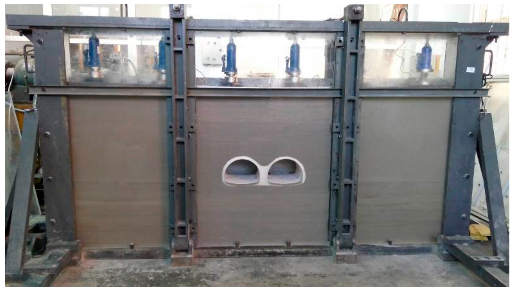
2. Experimental Study

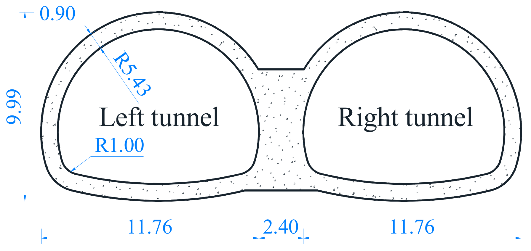
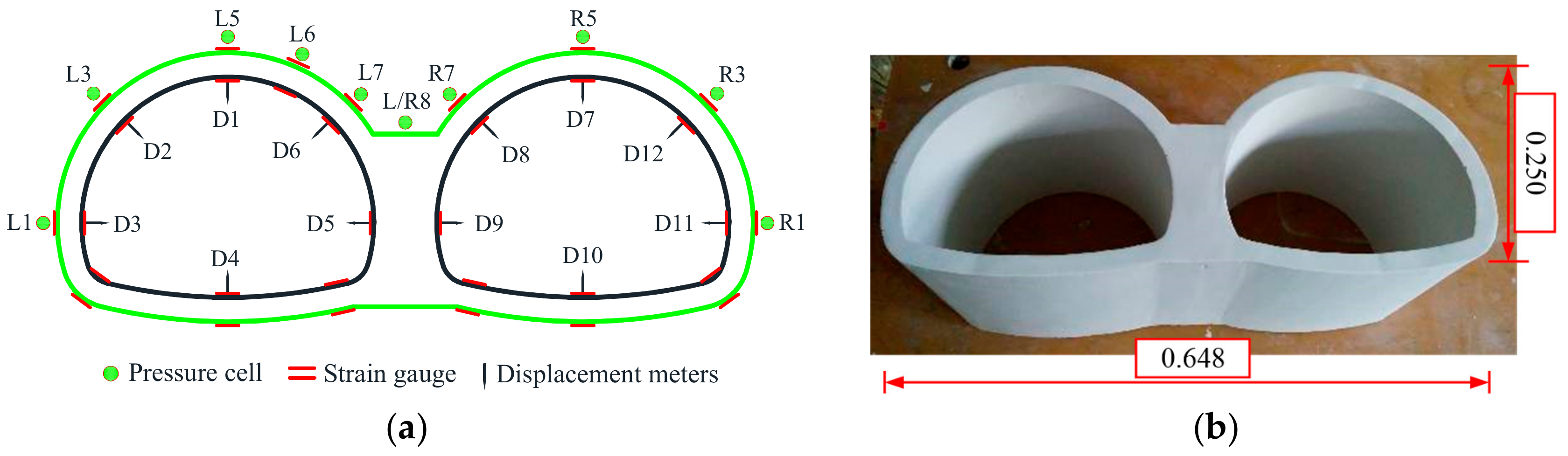
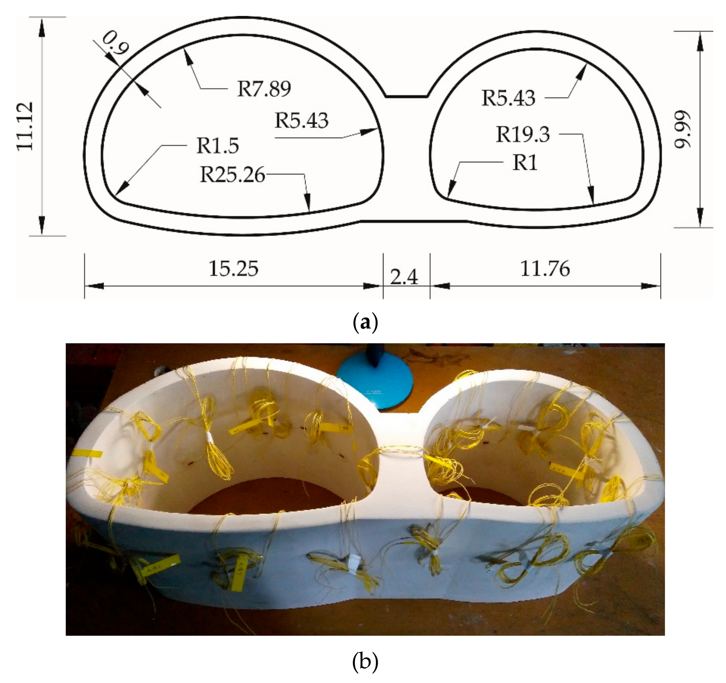
2.1. Experimental Schemes

Model tests were performed in a tank, with dimensions of 3.00 m × 1.62 m (length × height) in the plane, and 0.3 m in thickness, as shown in Figure 1. Due to the sufficient stiffness of all the model test apparatus with the loading capacity of more than 0.30 MPa and the structural deformation, which is less than 3 mm induced by the overload on the top surface of the model, the rigid constraint was approximatively applied along the longitudinal direction of the symmetrical double-arch tunnel. Thus, a series of model tests were conducted as a plane strain problem in this study.
According to the Chinese “Specifications for Design of Highway Tunnels: Section 1 Civil Engineering” [15], the normal cross-section of the symmetrical double-arch tunnel is depicted in Figure 2. The double-arch tunnel with a span of 25.92 m and a height of 9.99 m consists of twin tunnels, which are referred to as the “left tunnel” and “right tunnel”. The thickness of the primary lining and secondary lining are 0.30 m and 0.60 m, respectively.
Two model tests were performed to examine the failure behavior of a symmetrical double-arch tunnel, i.e., without voids located behind the lining (Model Test 1(MT1)) and with a void located on the top of the central wall of the double-arch tunnel (Model Test 2 (MT2)), as shown in Figure 3.

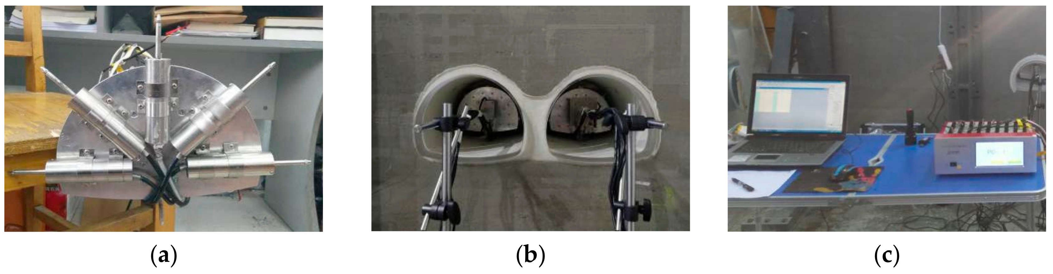
2.2. Experimental Process

Depending on the dimension of the model, the reduced scale Cl in the model tests was selected as 40. A type of acceptable modeling material was developed for satisfying the law of similarity; that is, a mixture of barite powder, silica sand, and petroleum jelly in a weight ratio of 4:10:1, and a mixture of water and gypsum in a weight ratio of 0.9:1 was selected for the lining. Various laboratory tests were performed, including static triaxial tests to determine the elastic modulus and Poisson’s ratio, direct shear tests to determine the cohesion and friction angle, and density tests to determine the unit weight of the ground. A set of compressive strength tests on cylinders with different weight ratios were carried out to achieve the elastic modulus and uniaxial strength of the lining. The model parameters of the lining and the surrounding soils are summarized in Table 1. Note that it is difficult to completely meet the similarity criteria. The unit weight of the model lining is 8.3 KN/m3, which is not strictly consistent with the prototype. However, the influence of the unit weight of the lining on the failure behavior of the lining was generally negligible.
Corresponding to the prototype value, the overburden depth of the tunnel in the model was 0.47 m. The lining thickness was 0.09 m. The model was fixed with 32 strain gauges located at the extrados and intrados of the tunnel lining to monitor the lining stress at every load step. There were a total of ten pressure cells around the double-arch tunnel to monitor the earth pressure acting on the lining. In addition, twelve displacement meters were used to monitor the lining deformation. As shown in Figure 4a, six displacement meters fixed on a metal plate were employed to monitor the radial displacement of the lining at the vault, both haunches, sidewall, invert, and central wall of the double-arch tunnel. Then, the two testing devices were installed inside the left and right tunnel, respectively, as shown in Figure 4b. Finally, all the displacement meters were connected with the strain indicator, and the measuring results could be obtained from the analysis software in the computer in Figure 4c.
The layout of measuring points (MPs) is shown in Figure 5a. The letter “L” or “R” of the MP label indicates the “left tunnel” or the “right tunnel”, respectively. Moreover, the letter “D” indicates the “displacement meter”. The model entity of the tunnel lining is shown in Figure 5b.
The model tests are mainly divided into 3 steps: Firstly, the model ground was constructed layer by layer, while the tunnel was embedded at the preset place. Secondly, the ground within the scope of cavities was removed by manual excavation from the steel plate on the back of the tank. Finally, the overload was gradually increased by 0.01 MPa intervals until 0.15 MPa (6.0 MPa in the prototype).

2.3. Experimental Results

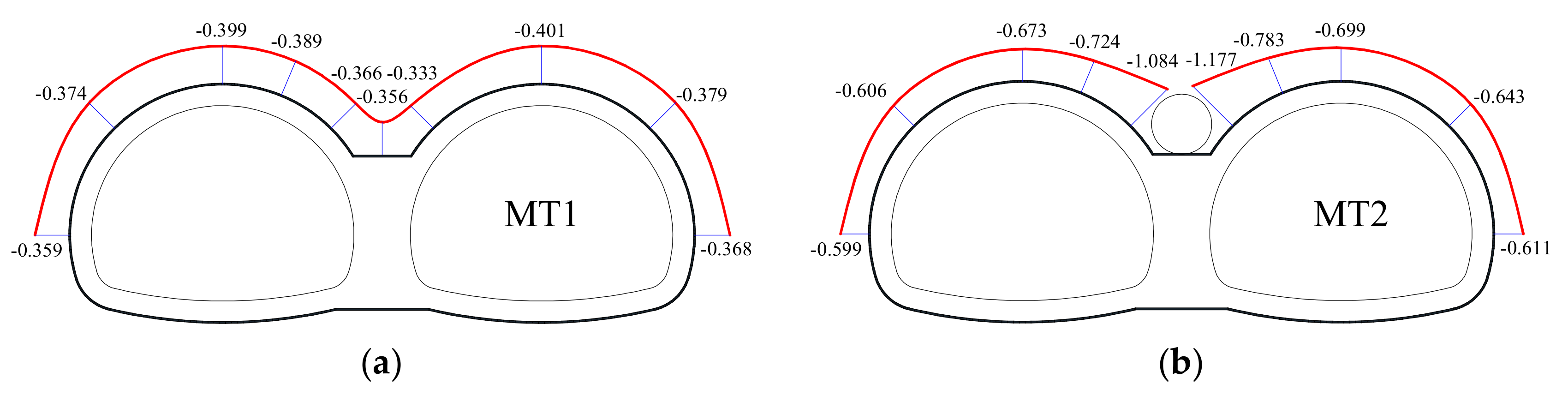
2.3.1. Earth Pressure Distribution

When the overload reached 0.01 MPa (0.40 MPa in the prototype), the changes in earth pressure acting on the lining attained from the two model tests are presented in Figure 6. The maximum value of 0.401 MPa appeared at the vault of the double-arch tunnels. The magnitude of the earth pressure acting on the outside haunch was slightly larger than that on the inside haunch. The earth pressure acting on the sidewall was 0.359 MPa and 0.368 MPa, respectively. The overall double-arch tunnel linings approximatively carried uniform stress. Compared with the case with no void, the introduction of a void significantly changed the earth pressure distribution, especially for the area on both sides of the void, which had the maximum value of 1.177 MPa. The magnitude of earth pressure acting on the shoulder and haunch was more than 0.600 MPa. The distribution of earth pressure acting on the double-arch tunnel lining in Model Test 1 and 2 was generally symmetrical.

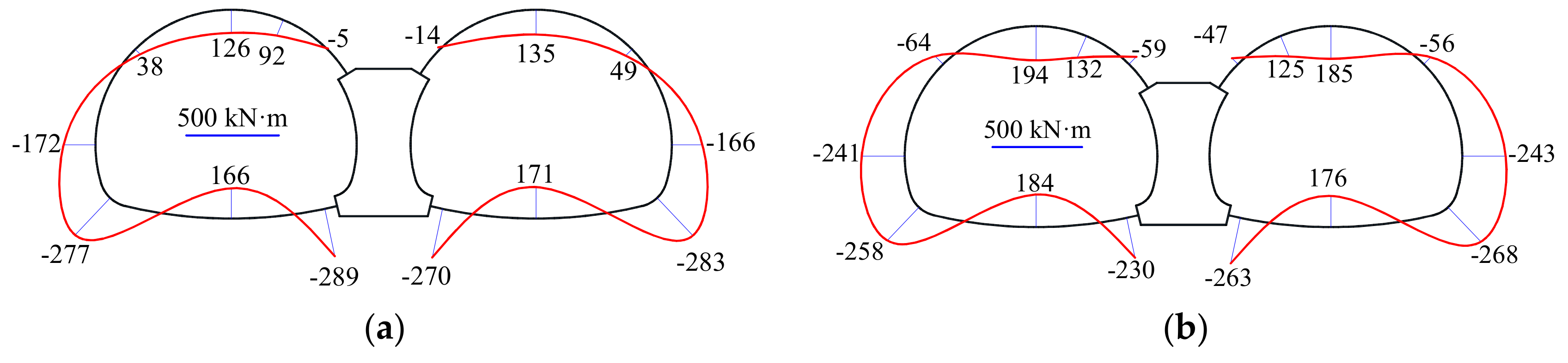
2.3.2. Distribution of Bending Moments

Figure 7 shows the distribution of bending moments in the lining attained from the model tests. In Model Test 1, positive bending moments mainly appeared at the invert, crown, and shoulder, which indicated the tensile stress occurred at the inner fiber of the lining. The maximum value of 171 kN·m appeared at the invert of the right tunnel. Instead, negative bending moments were attained at the haunch, sidewall, and arch spring. The maximum value of 289 kN·m occurred on the left corner of the central wall. Compared with Model Test 1, the value at the inside haunch increased and the bending moments in the left haunch reached -59 kN·m in Model Test 2. The value of 194 kN·m at the vault of the left tunnel in Model Test 2 was larger than that in Model Test 1. The introduction of voids resulted in the concentration of stress on both sides of a void located on the top of the central wall of the double-arch tunnel with an associated shortage of carrying capacity.

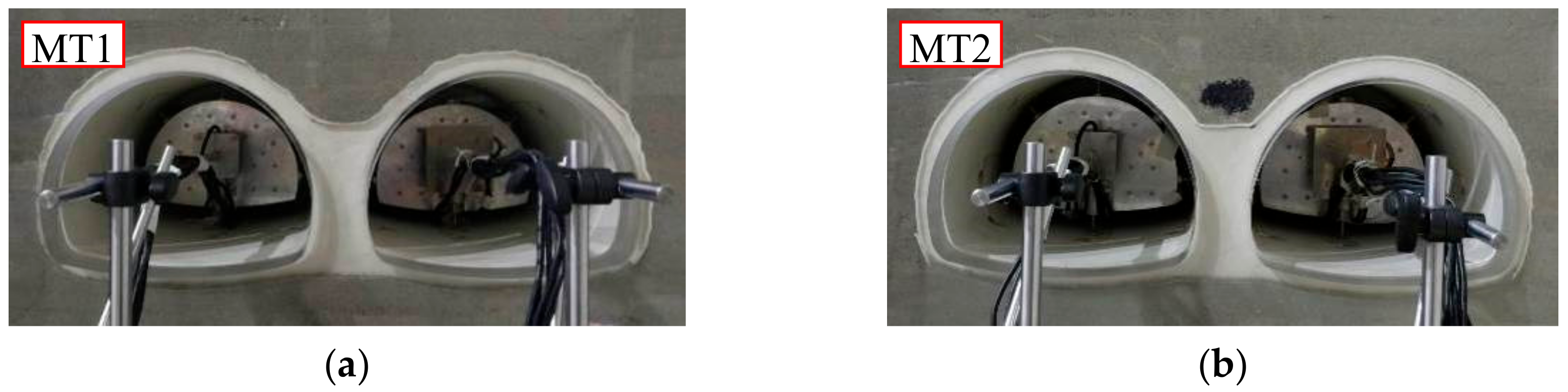
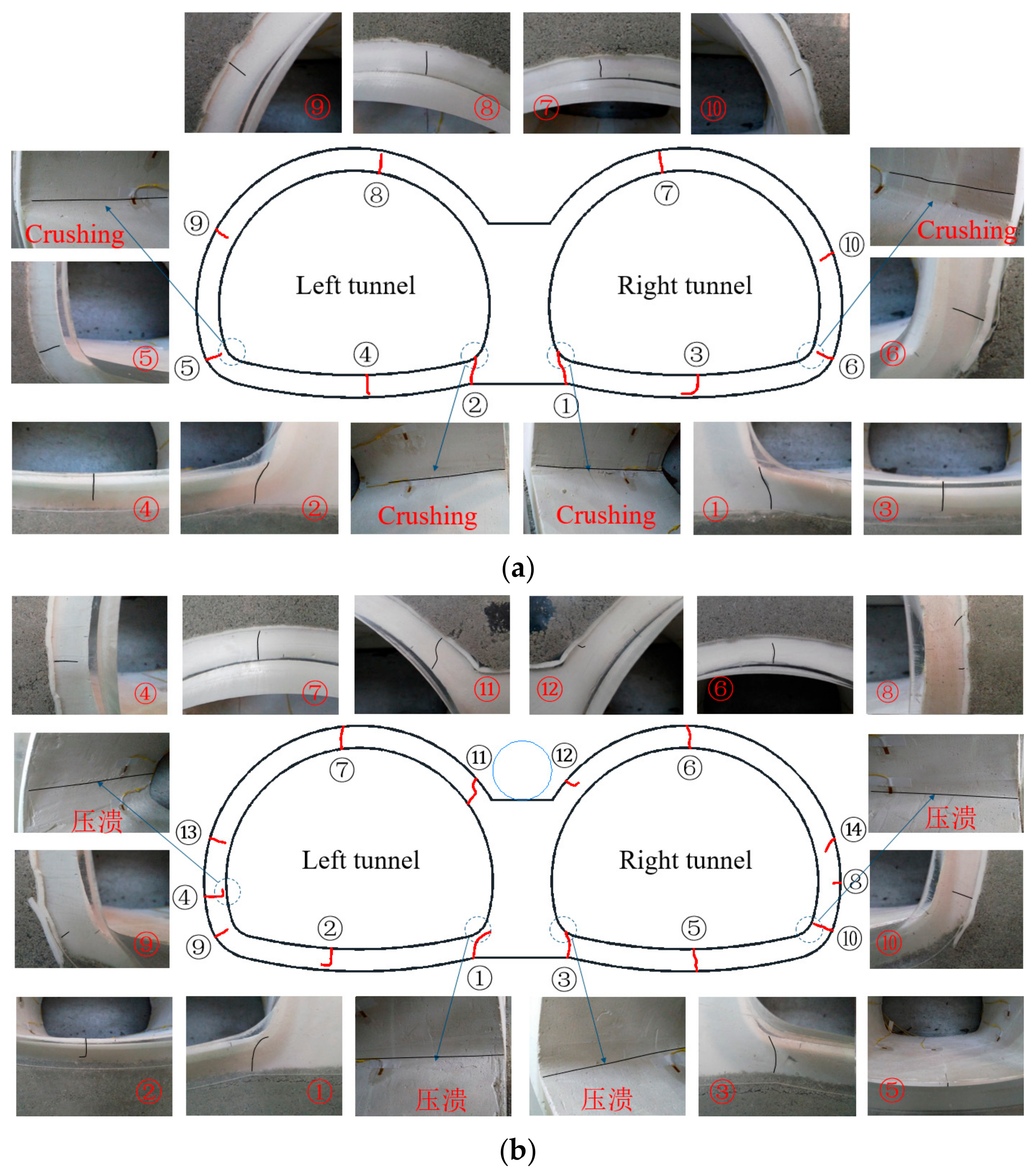
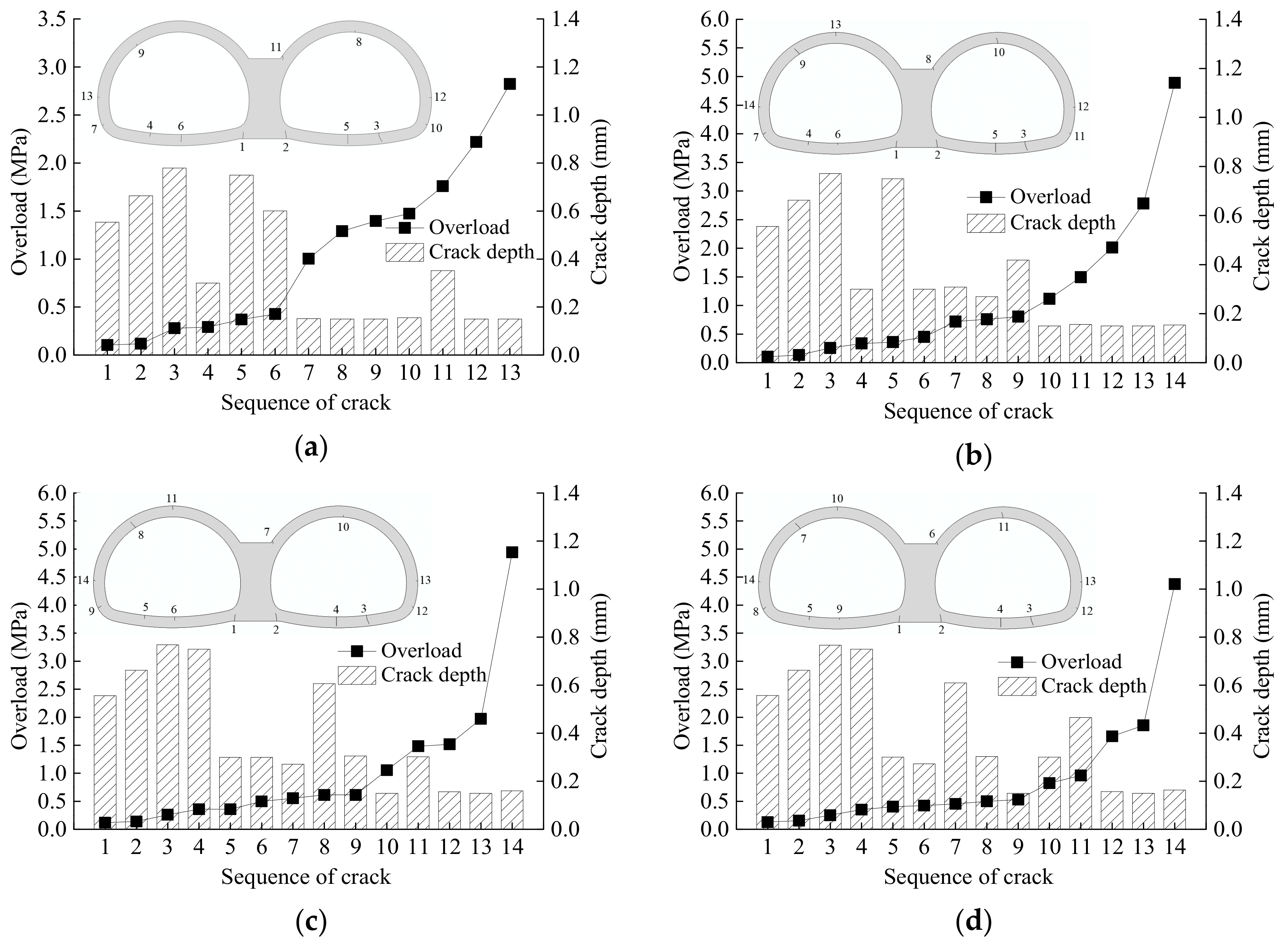
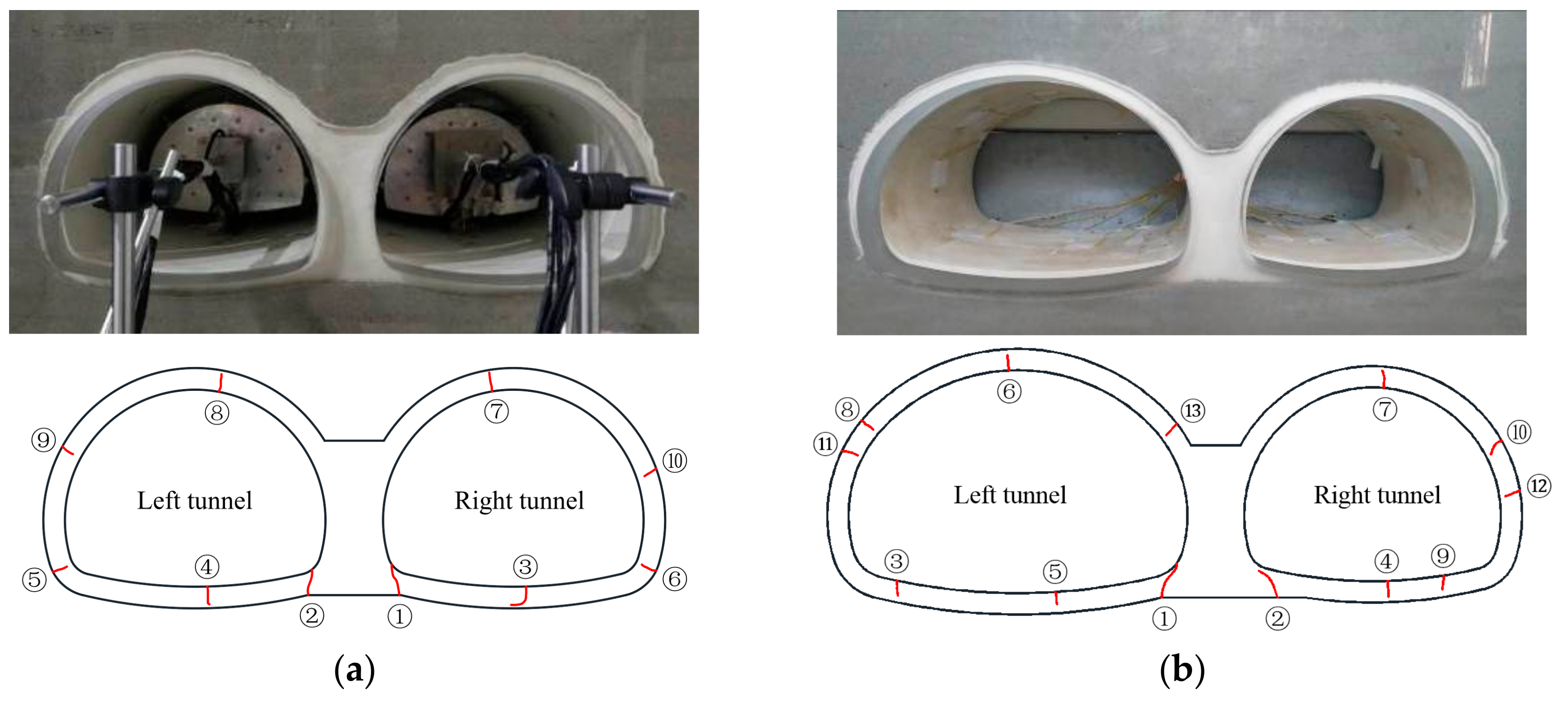
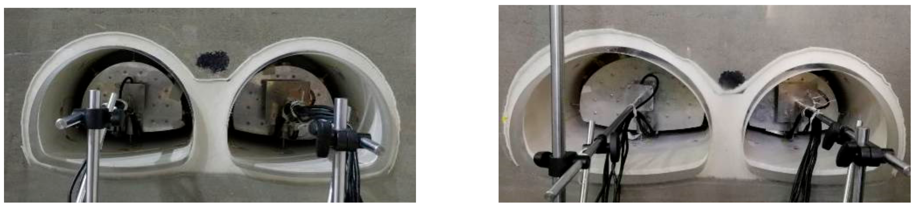
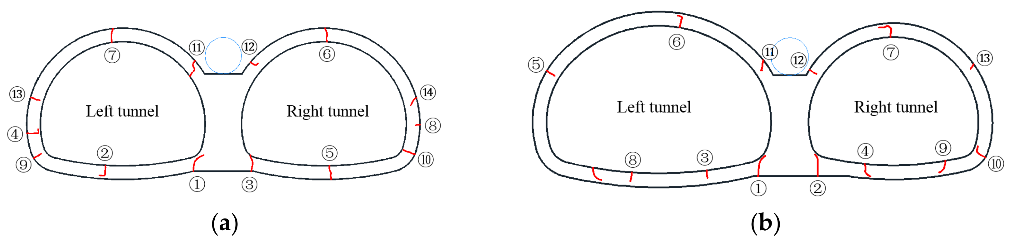
2.3.3. Lining Failure and Cracking

The distribution of lining cracks is shown, attained from model tests in Figure 8. Herein, the serial numbers indicate the sequential order of the cracks. Similar lining failure behavior was found in the two model tests. When the overload was less than 0.02 MPa, cracks were not observed, indicating the self-stability of the tunnel. As the overload progressed, inclined cracks appeared firstly at the outer fiber of the lining at the bottom of the central wall. Subsequently, the existing cracks continuously expanded and new cracks were noted to appear at the inner fiber of the invert. Moreover, the part in the inner fiber of the lining at the bottom of the central wall and the arch spring were all crushing. However, an obvious difference existed in the areas in the close vicinity of the void. Compared with the case without voids, when the void was introduced on the top of the central wall, cracks with a larger opening width and depth at the inner fiber of the vault in Model Test 2 occurred earlier than that in Model Test 1. Moreover, there was no rock reaction force on the inside of the void, so that larger tensile stress at the outer fiber of the lining on the upper corner of the central wall appeared, which caused outside cracking and an inside crushing phenomenon in Model Test 2.
The failure pattern of the symmetrical double-arch tunnels attained in Model Test 1 and 2 was generally symmetrical relative to the centerline of the tunnel. While voids behind the lining with different sizes are likely to exist at different locations, e.g., the vault, haunch, shoulder, and sidewall in the real tunnel engineering. According to previous research, the internal force in the lining is greatly affected by the existence of voids, in particular at the location and size of voids [7,11,14]. Model tests have several shortcomings, e.g., being time-consuming, of high cost, and with poor flexibility, while the numerical analysis can compensate for such experimental deficiencies. Thus, several studies evaluate the impact of voids behind the lining on the failure behavior of the double-arch tunnels numerically.

3. Numerical Study

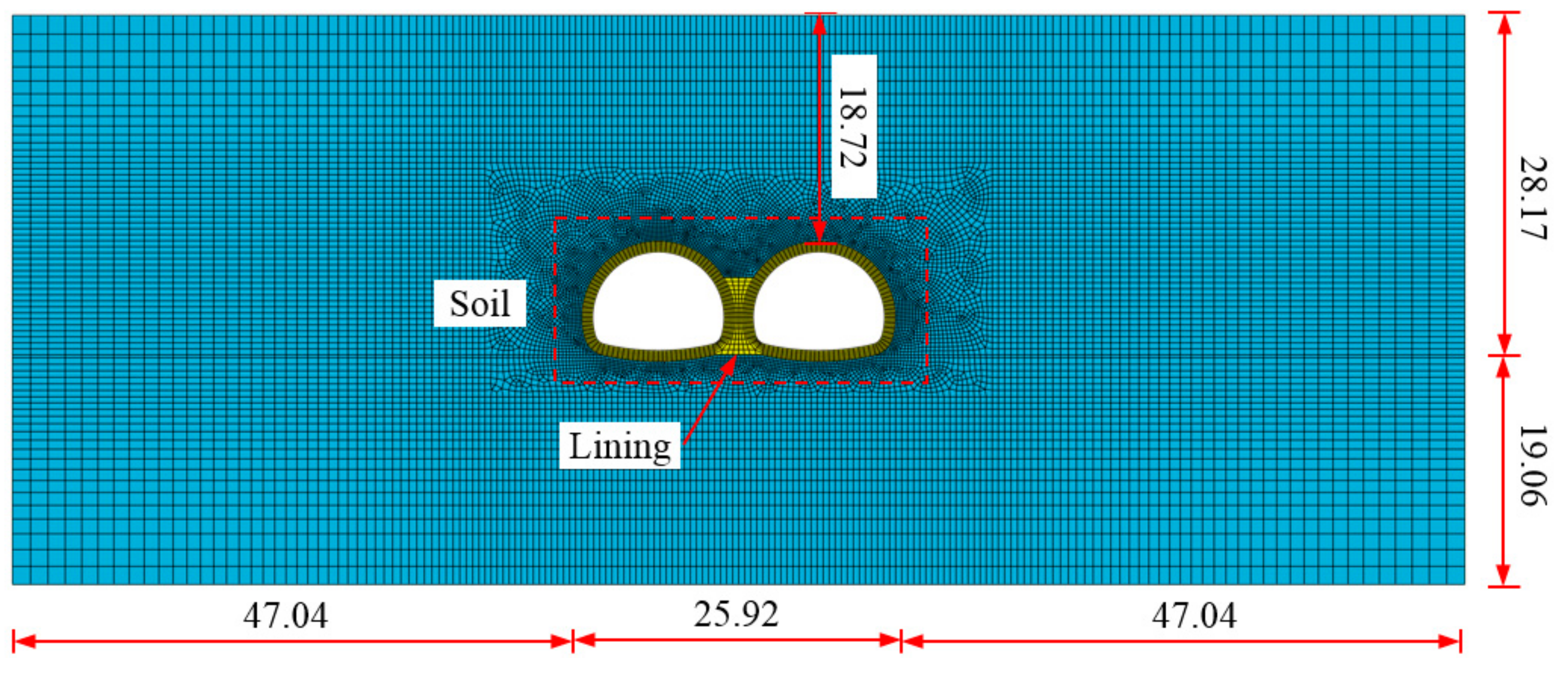
3.1. Numerical Model

The two-dimensional (2D) numerical analysis was conducted using the general nonlinear finite element code Abaqus. The extended finite element method was used for modeling lining cracks. The 2D model dimensions were selected to be 120 m (length) × 47.23 m (width), where cover depth 18.72 m was the vertical distance from the ground surface to the vault, as shown in Figure 9. The tunnel lining was modeled using the plane strain elements CPE4R (4-node bilinear, reduced integration with hourglass control). There were a total of 1116 zone elements in the tunnel lining model. Regarding the boundary conditions, the displacements were set to be zero in all directions at the bottom. The displacements in two horizontal directions were restrained, and only vertical displacement in the vertical direction was allowed on both side boundaries.
The Mohr–Coulomb elastoplastic constitutive model was adopted for the soil, while the tunnel lining was modeled using the damaged mechanics model of materials available in the Abaqus library [16,17]. We use the code to specify material damage initiation criteria and associated damage evolution. Once an initiation criterion is met, Abaqus applies the associated damage evolution law to determine material degradation. The maximum principal stress damage initiation criteria were used for modeling cracks and predicting damage initiation in the extended finite element method enriched region. The parameters of the damaged mechanics model include density, elastic modulus, Poisson’s ratio, maximum principal stress, fracture energy, and damage stabilization cohesive. The maximum principal stress and fracture energy were used for the emergence and propagation of cracks and the damage stabilization cohesive was used to improve the model convergence. In light of the “Chinese Code for Design of Concrete Structures” [18], due to the lining composed of C40 concrete, the max principal stress in the lining model was selected as the tensile strength of 2.40 MPa, and the normal mode fracture energy, shear mode fracture energy first direction, and shear mode fracture energy second direction were all 80 N/m [17]. The viscous coefficient was selected as 0.0001 in light of the Abaqus v6.14 Documentation [16]. A surface-to-surface contact interaction between the double-arch tunnel lining and the surrounding soils was created to specify the master and slave surfaces for the pressure penetration, in which penalty contact stiffness defined with an exponential law was applied normally, and coulomb friction (the friction coefficient was 0.8) was applied tangentially [14]. The ultimate compressive strain of the concrete was 0.0033 in light of the “Chinese Code for Design of Concrete Structures” [18]. Once the magnitude of the compressive strain of concrete exceeds 0.0033, the compressive failure of the concrete occurs. The main parameters used in modeling the tunnel lining and the soils are summarized in Table 2.

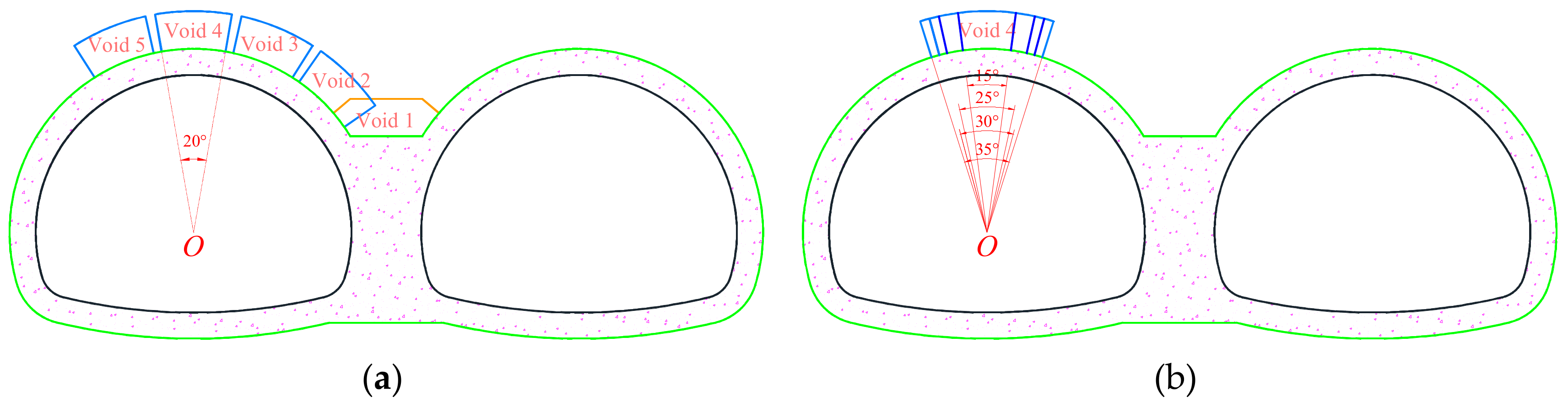
3.2. Numerical Schemes

Due to complicated construction workmanship and improper backfilling, voids are also prone to developing behind the lining of double-arch tunnels. According to the inspection results of double-arch tunnels in Sichuan and Chongqing, the depth or height of voids behind the lining generally ranged from 0.15 to 0.50 m, and the maximum value reached 1.09 m [19]. In practical engineering, field monitoring remains a generally recognized approach for understanding the deformation of the ground and the neighboring structures [20,21,22], whereas there are numerous voids with different sizes developed around the double-arch tunnel lining. Different arrangements and sizes of voids can change stress, deformation, and failure of the lining. Therefore, it has practical importance to study the effect of changes in the location and size of the void behind the lining by numerical analysis. Ten numerical tests were performed to investigate the effects of voids behind the lining on the failure behavior of the double-arch tunnels: (1) void location and (2) void size.
Assuming that all the voids behind the lining have a simplified annular-sector geometry, the void size is given in the light of the angle, which is formed between two lines determined from point O to the left and the right edge of voids, respectively. The letter “O” indicates the center of the left tunnel. The void size ranging from 15° to 35° are realistic and close to that inspected in the real double-arch tunnel engineering. In this study, the void depth of 1.30 m is the same for all cases, which is about 1.2 times larger than the maximum result of 1.09 m attained from the real double-arch tunnel engineering in Sichuan and Chongqing, China. The void depth may be larger during tunneling adjacent to the natural karsts. Five simulations with a void behind the lining were performed at different locations, namely central wall, right haunch, right shoulder, vault, and left shoulder (Numerical Tests 2–6). The angle of all voids was taken as 20°, except for the vault where numerical tests were performed with angles of 15°, 25°, 30°, and 35° (Numerical Tests 7–10), as listed in Table 3. It is worth noting that the whole area of the void with irregular shape introduced on the top of the central wall of the double-arch tunnel is basically equal to that introduced at other locations in Figure 10a.
The numerical modeling processes were related as follows: The model was initially set up to reach equilibrium with a gravitational gradient in situ stress state. Deformation and velocity caused by the initial equilibrium were reset to zero. Once the simulation converged to an equilibrium state, the following step was to execute the full face excavation and the lining support. Meanwhile, excavation of a void behind the lining was simulated by deleting the elements located inside the void perimeter for Numerical Tests 2–10. Finally, the overload on the top surface of the model was gradually increased until the tensile failure of the tunnel lining formed. The next load step was applied only if the current simulation converged to an equilibrium state. The overload ranged from 0 to 6.00 MPa.

3.3. Numerical Results

3.3.1. Effect of Void Location

The final crack depth and corresponding cracking load, as well as the failure laws of the lining with voids at different locations are presented in Figure 11. The number range from 1 to 15 represents the sequence of lining cracks. Compared with the case with no void, the introduction of a void substantially changes the lining failure. Given that the presence of a void can generally preclude any symmetry, it seems that the lining cracks adjacent to the void are more sensitive to the location of the void. Lining cracks are more likely to appear at the outer fiber of the double-arch tunnel lining on both sides of the central wall close to the shoulder when voids are located at the vault, shoulder, and haunch. Note that the results for voids located at the shoulder and haunch indicate that lining cracks occur at the outer fiber of the lining on the inside of the void. Lining cracks sometimes can be observed at the inner fiber of the double-arch tunnel lining on the side of the void.
The distribution of the minimum principal strain in the lining with voids at different locations is presented in Figure 12. The red numbers stand for the compressive failure of the lining determined by the ultimate compressive strain of concrete. The compressive failure mainly occurred at the inner fiber of the lining, i.e., the bottom of the central wall close to the invert, the top of the central wall close to the shoulder, sidewall, and arch spring. The maximum value of 0.00489 appeared at the bottom of the central wall in Numerical Test 6. In Numerical Tests 2–6, the results indicate that the location of the void has a significant influence on the failure behavior of the double-arch tunnels.

3.3.2. Effect of Void Size

The failure patterns of the tunnel lining with different size of voids at the vault, i.e., 15°, 25°, 30°, and 35°are presented in Figure 13. The changes in the failure patterns of the lining with the angle of the void are similar to those depicted in Figure 11e. With a void of 15°, there were no cracks at the outer fiber of the vault of the left tunnel. With larger voids the tensile stress of the lining at the vault of the left tunnel increased, generally in the form of earlier cracking on the inside of the void. As the angle of the void increased, changes in the location of the lining cracks at the inner fiber of the lining on the left side of the void and at the inner fiber of the vault of the right tunnel occurred. With changes ranging from 20° up to 35°, the depth of the crack which occurred at the outer fiber of the lining on the inside of the void increased, while the depth of the crack at the tunnel invert on the same side of the void was reduced. As shown in Figure 14, when the void was introduced at the vault of the left tunnel and its angle ranged from 15° up to 35°, the minimum principal strain in the tunnel lining on the top of the central wall adjacent to the shoulder of the right tunnel gradually increased.
Figure 15 shows the distribution of the internal forces in the lining of double-arch tunnels. The stress state of double-arch tunnels was seriously influenced by the existence of voids. The presence of voids resulted in the concentrated load to the lining that induced positive bending moments in the lining on both sides of the void and negative bending moments in the lining on the inside of the void. With the growth in void size, the bending moments in the lining on the inside of the void increased, and cracks were more likely to appear at the outer fiber of the lining on the inside of the void.
When voids were introduced at the central wall, the existence of voids led to a large increase in the thrust forces and bending moments in the lining at the central wall close to the shoulder compared with the base case. Therefore, the existence of voids located at the central wall was critical, particularly for the double-arch tunnels. The largest changes of the lining internal forces in Numerical Tests 2–6, with respect to those attained from the base case, occurred in the lining close to the central wall, i.e., the vault, shoulder, and haunch. The magnitude of thrust forces in the lining at the invert was normally smaller than that of other positions.

4. Comparisons with Asymmetrical Double-Arch Tunnels

The cross-section of a typical asymmetrical double-arch tunnel considered in the previous paper [14] is shown in Figure 16a. The geometrical shape of the symmetrical and asymmetrical double-arch tunnels is significantly different, especially since the latter has a large-section tunnel with a span of 15.25 m and a height of 11.12 m. The reduced scale in the model tests was also selected 40. The lining thickness is the same as the symmetrical double-arch tunnel. The model entity of the asymmetrical double-arch tunnel fixed with 32 strain gauges at the extrados and intrados of the lining is shown in Figure 16b.

4.1. Without Voids behind the Lining

The failure pattern of the lining of symmetrical and asymmetrical double-arch tunnels without voids behind the lining obtained from the experimental studies is presented in Figure 17. The numbers ranging from 1 to 13 represent the sequence of cracks. There are some similarities and differences between the symmetrical and asymmetrical double-arch tunnels. The location of the first crack is the same, i.e., the lining on the corner of the central wall of the double-arch tunnel, while the earlier lining cracking occurred in the large-section tunnel. It seems that the carrying capacity of the large-section tunnel is less than the other one of asymmetrical double-arch tunnels, which is prone to complicate cracking compared with symmetrical double-arch tunnels. Finally, an inclined crack was noted to appear at the outer fiber of the lining on the left upper corner of the central wall close to the large-section tunnel, which possibly results in excessive deformation even serious damage.

4.2. Without a Void on the Top of the Central Wall

The failure pattern of the lining of symmetrical and asymmetrical double-arch tunnels with a void on the top of the central wall obtained from the experimental studies is presented in Figure 18. When a void was introduced behind the central wall of the symmetrical and asymmetrical double-arch tunnels, the failure pattern of the lining of the small tunnel is generally similar, while the crack at the outer fiber of the arch spring of the large-section tunnel was not found. Compared with the case without voids, the introduction of a void behind the central wall leads to more serious damage and earlier emergence of cracks in the lining on the upper corner of the central wall of symmetrical and asymmetrical double-arch tunnels. However, the results attained from the model tests were generally consistent with the results attained from the numerical analysis. Void location, void size, and tunnel shape are key factors affecting the failure pattern of double-arch tunnels.

5. Summary and Conclusions

Two model tests were first performed to investigate the failure pattern of symmetrical double-arch tunnels without voids and with a void behind the central wall, respectively. Then, a series of numerical analyses were conducted to examine the effect of voids behind the lining on the failure pattern and internal forces in the lining of symmetrical double-arch tunnels. Moreover, comparisons with symmetrical tunnels and asymmetrical double-arch tunnels induced by the presence of voids behind the central wall were also made. The conclusions can be drawn as follows:
(1)
The existence of a void behind the central wall, affecting the re-distribution of the earth pressure compared with the case without voids, results in the concentration of stress on both sides of the void located on the top of the central wall, associated with it the emergence of cracks in the lining on the upper right and left corners of the central wall of symmetrical double-arch tunnels.
(2)
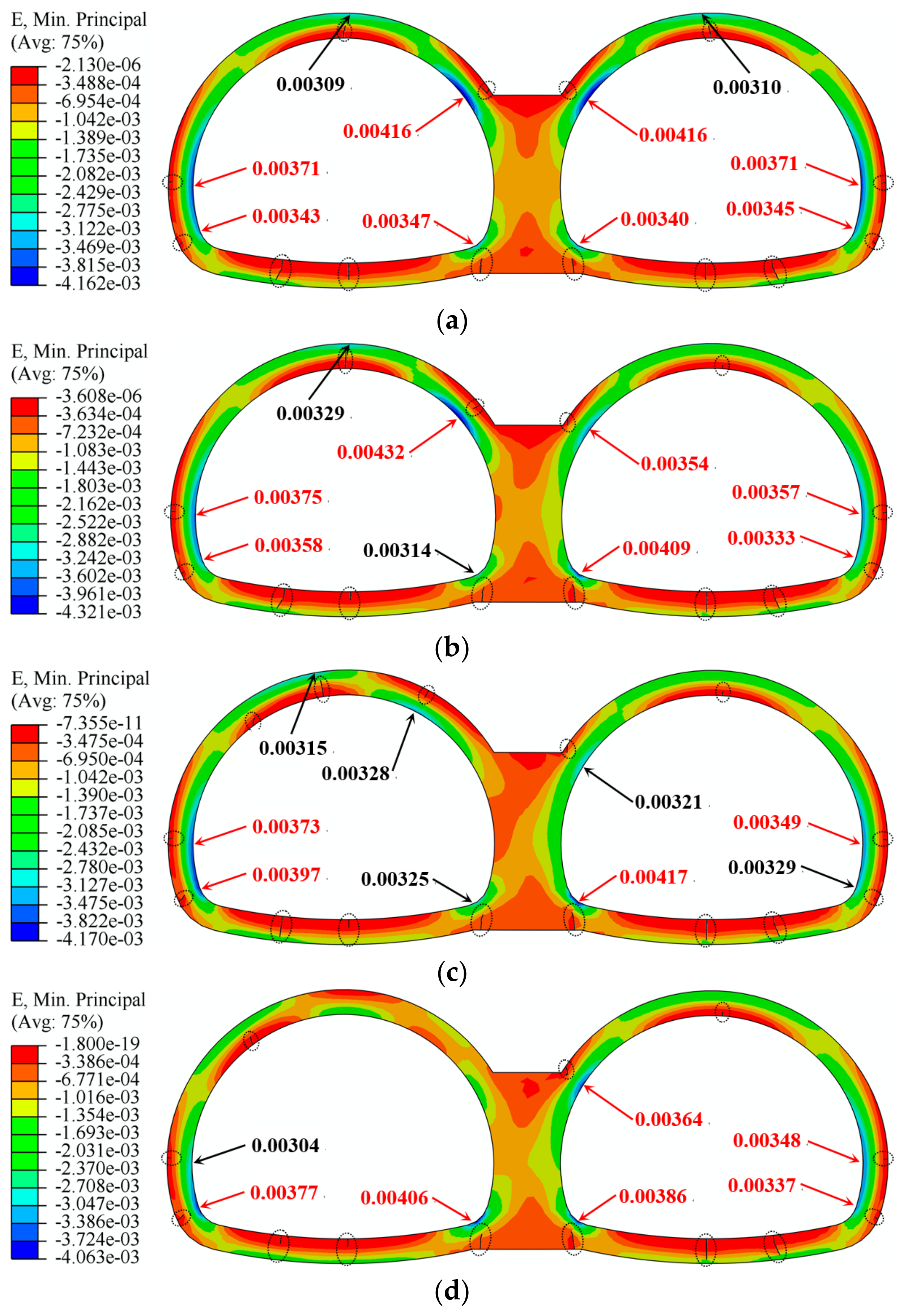
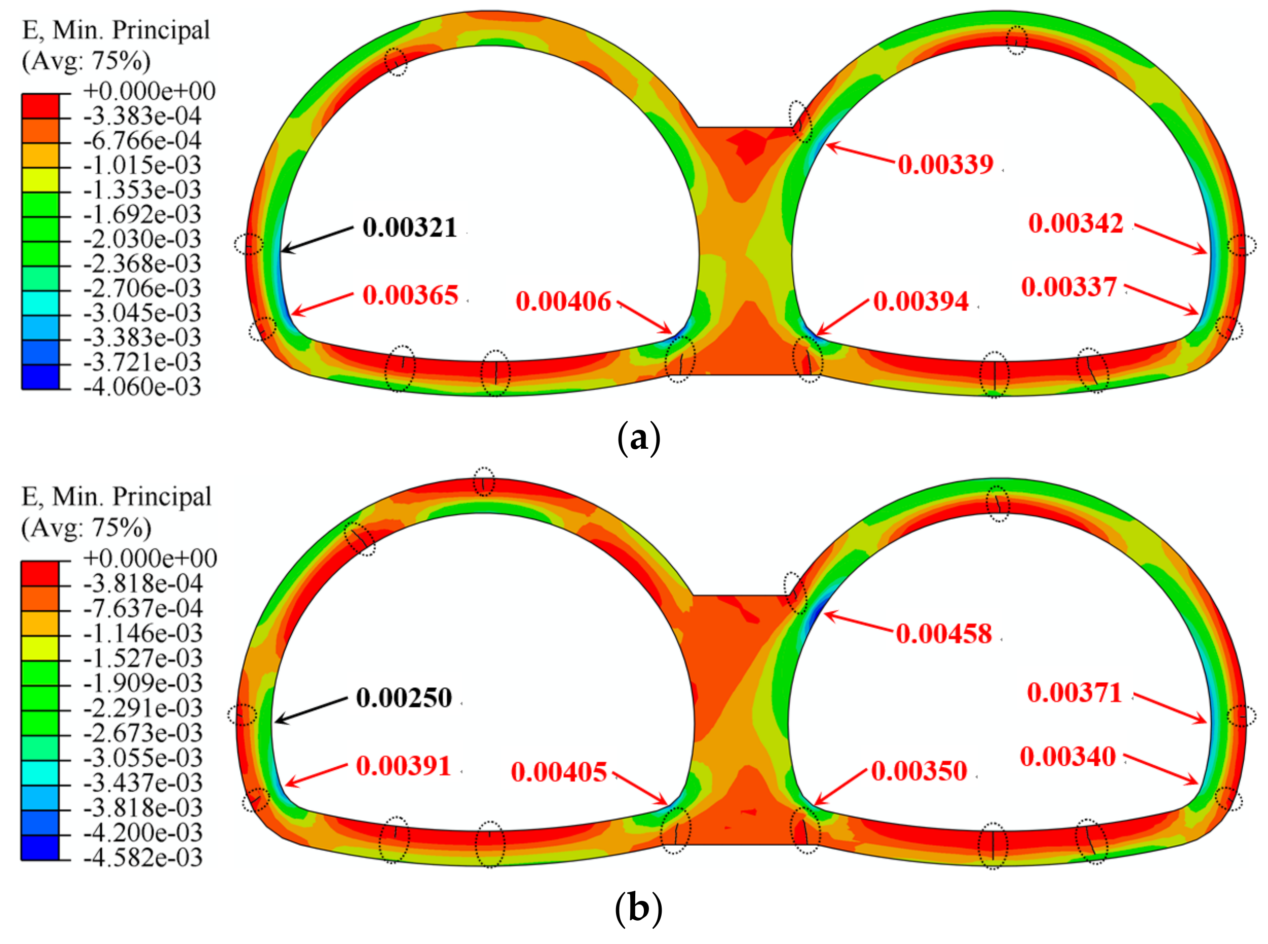
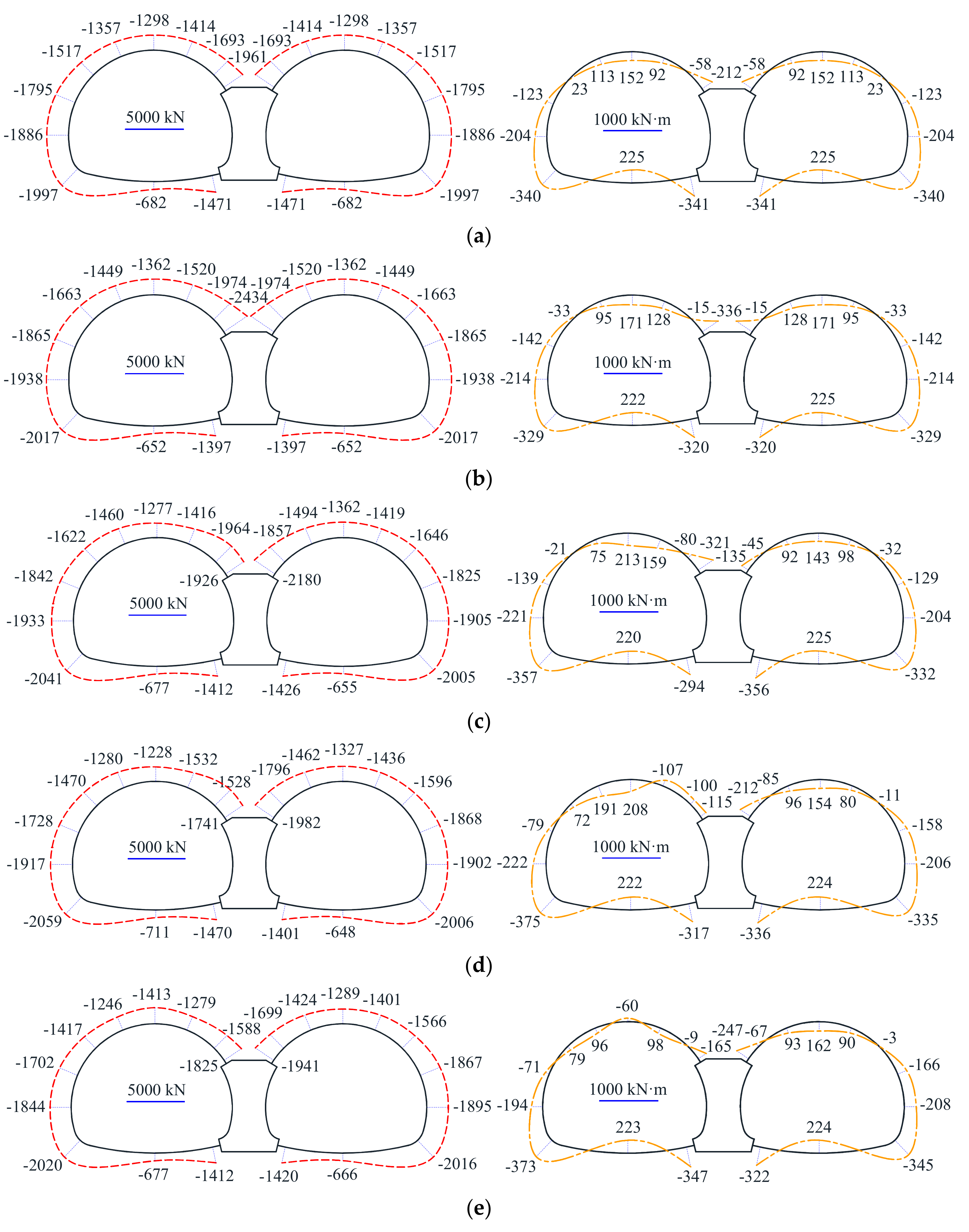
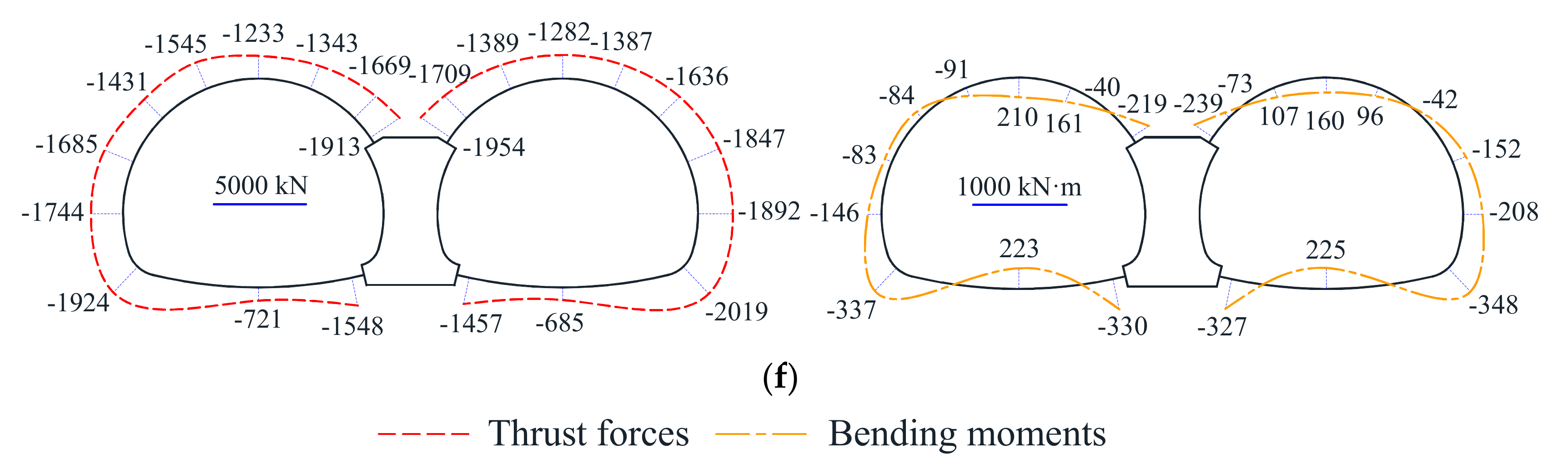
Due to the presence of voids behind the lining, significant changes in the internal forces in the lining were found at the areas in close vicinity of the void, whereas only a few changes were found at the invert and central wall. The lining at the bottom of the central wall of the symmetrical double-arch tunnel, which is regarded as the weak part, suffered the most severe damage.
(3)
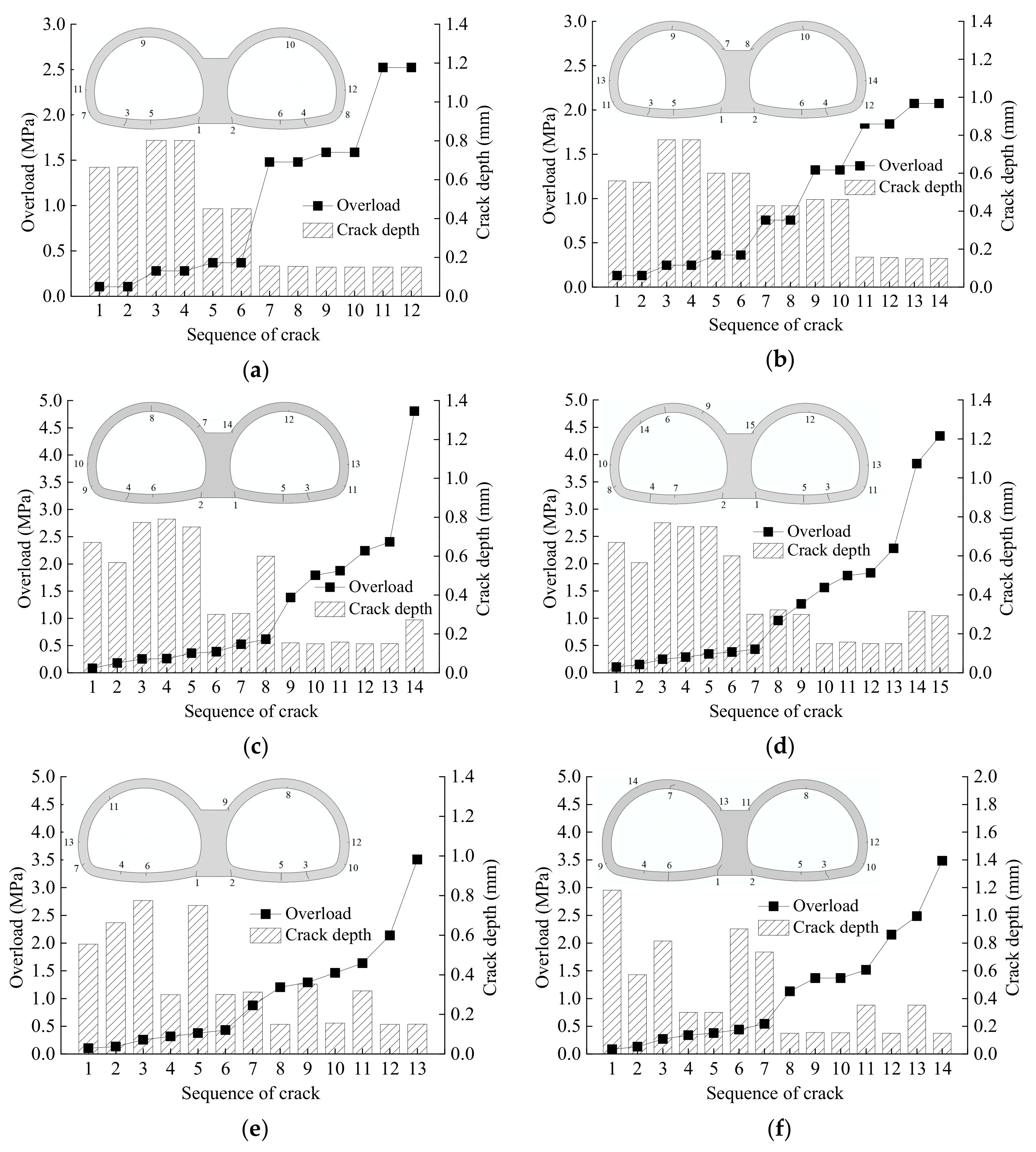
Given that the presence of a void can generally preclude any symmetry, the cracks adjacent to the central wall of symmetrical double-arch tunnels are more sensitive to the location of the void. With the growth in the angle of voids, the positive bending moments in the lining on the inside of the void increased, and the cracks are likely to appear at the outer fiber of the lining.
(4)
Compared with asymmetrical double-arch tunnels, the introduction of a void behind the central wall leads to lighter damage and later emergence of cracks in the lining on the upper left corner of the central wall. The location of the initial cracking of the double-arch tunnels is basically the same, while the lining failure of the large-section tunnel seems to be more complicated.

Author Contributions

Y.X. designed research and contributed to the funding; X.Z. carried out the model tests, completed most of the simulations, and wrote the manuscript; B.M. helped in the numerical simulations and analyzed the experimental results; Z.Y. revised the manuscript and checked for typographical errors.

Funding

This research was funded by the National Natural Science Foundation of China (51868062), Science and Technology Research and Development Program of China Railway Corporation (N2018G029,J2017G001), and Key Laboratory of Urban Underground Engineering of Ministry of Education (Beijing Jiaotong University).

Acknowledgments

The authors are deeply thankful to the reviewers for their valuable suggestions to improve the quality of the paper. The authors would like to express sincere acknowledgment to Zhang Chengping from Beijing Jiaotong University who provided instructive advice and useful suggestions during the research.

Conflicts of Interest

The authors declare no conflict of interest regarding the publication of this paper.

References

  1. Zhang, C.P.; Han, K.H.; Zhang, D.L. Face stability analysis of shallow circular tunnels in cohesive-frictional soils. Tunn. Undergr. Space Technol. 2015, 50, 345–357. [Google Scholar] [CrossRef]
  2. Li, W.; Zhang, C.P.; Zhu, W.J.; Zhang, D.L. Upper-bound solutions for the face stability of a non-circular NATM tunnel in clays with a linearly increasing undrained shear strength with depth. Comput. Geotech. 2019, 114, 103136. [Google Scholar] [CrossRef]
  3. Han, K.H.; Zhang, C.P.; Zhang, D.L. Upper-bound solutions for the face stability of a shield tunnel in multilayered cohesive–frictional soils. Comput. Geotech. 2016, 79, 1–9. [Google Scholar] [CrossRef]
  4. Li, W.; Zhang, C.P.; Zhang, X. Stability analysis of the tunnel face in the cohesive-frictional soils considering the arch effect and rotational mechanism. J. Chin. Inst. Eng. 2018, 41, 697–709. [Google Scholar] [CrossRef]
  5. Lai, J.X.; Qiu, J.L.; Fan, H.B.; Chen, J.X.; Hu, Z.N.; Zhang, Q.; Wang, J.B. Structural safety assessment of existing multiarch tunnel: A case study. Adv. Mater. Sci. Eng. 2017, 2017, 1697041. [Google Scholar] [CrossRef]
  6. Yan, Q.X.; Zhang, C.; Lin, G.; Wang, B. Field monitoring of deformations and internal forces of surrounding rocks and lining structures in the construction of the Gangkou double-arched tunnel-A case study. Appl. Sci. 2017, 7, 169. [Google Scholar] [CrossRef]
  7. Meguid, M.A.; Dang, H.K. The effect of erosion voids on existing tunnel linings. Tunn. Undergr. Space Technol. 2009, 24, 278–286. [Google Scholar] [CrossRef]
  8. Gao, Y.; Jiang, Y.J.; Li, B. Estimation of effect of voids on frequency response of mountain tunnel lining based on microtremor method. Tunn. Undergr. Space Technol. 2014, 42, 184–194. [Google Scholar] [CrossRef] [Green Version]
  9. Yasuda, N.; Tsukada, K.; Asakura, T. Elastic solutions for circular tunnel with void behind lining. Tunn. Undergr. Space Technol. 2017, 70, 274–285. [Google Scholar] [CrossRef]
  10. Leung, C.; Meguid, M.A. An experimental study of the effect of local contact loss on the earth pressure distribution on existing tunnel linings. Tunn. Undergr. Space Technol. 2011, 26, 139–145. [Google Scholar] [CrossRef]
  11. Wang, J.F.; Huang, H.W.; Xie, X.Y.; Bobet, A. Void-induced liner deformation and stress redistribution. Tunn. Undergr. Space Technol. 2014, 40, 263–276. [Google Scholar] [CrossRef]
  12. Li, S.C.; Yuan, C.; Feng, X.D.; Li, S.C. Mechanical behaviour of a large-span double-arch tunnel. KSCE J. Civ. Eng. 2016, 20, 2737–2745. [Google Scholar] [CrossRef]
  13. He, J.; Zhang, C.P.; Yang, G.B.; Wang, M.S. Experimental study on mechanical behavior of nonsymmetric multi-arch tunnel in sand-cobble ground. Chin. Civ. Eng. J. 2017, 50, 116–124. (In Chinese) [Google Scholar]
  14. Min, B.; Zhang, X.; Zhang, C.P.; Gong, Y.P.; Yuan, T.F. Mechanical behavior of double-arch tunnels under the effect of voids on the top of the middle wall. Symmetry 2018, 10, 703. [Google Scholar] [CrossRef]
  15. Ministry of Housing and Urban-Rural Development of the People’s Republic of China. JTG 3370.1-2018, Specifications for Design of Highway Tunnels: Section 1 Civil Engineering; China Communications Press Co., Ltd.: Beijing, China, 2019. (In Chinese) [Google Scholar]
  16. ABAQUS. Abaqus v6.14 Documentation; Dassault Systèmes: Providence, RI, USA, 2015. [Google Scholar]
  17. Yan, Q.X.; Xu, Y.J.; Zhang, W.L.; Geng, P.; Yang, W.B. Numerical analysis of the cracking and failure behaviors of segmental lining structure of an underwater shield tunnel subjected to a derailed high-speed train impact. Tunn. Undergr. Space Technol. 2018, 72, 41–54. [Google Scholar] [CrossRef]
  18. Ministry of Housing and Urban-Rural Development of the People’s Republic of China. GB 50010-2010, Code for Design of Concrete Structures; China Architecture & Building Press: Beijing, China, 2015. (In Chinese) [Google Scholar]
  19. Li, Z.H.; Zhu, H.H.; Ding, W.Q. Key Technology of Design and Construction for Highway Twin-Tunnel; China Communications Press: Beijing, China, 2010; pp. 223–224. (In Chinese) [Google Scholar]
  20. Zhang, C.P.; Cai, Y.; Zhu, W.J. Numerical study and field monitoring of the ground deformation induced by large slurry shield tunnelling in sandy cobble ground. Adv. Civ. Eng. 2019, 2019, 4145721. [Google Scholar] [CrossRef]
  21. Zhang, X.; Zhang, C.P.; Wang, J.C. Effect of closely spaced twin tunnel construction beneath an existing subway station: A case study. J. Test. Eval. 2018, 46, 1559–1573. [Google Scholar] [CrossRef]
  22. Zhang, C.P.; Zhang, X.; Fang, Q. Behaviors of existing twin subway tunnels due to new subway station excavation below in close vicinity. Tunn. Undergr. Space Technol. 2018, 81, 121–128. [Google Scholar] [CrossRef]
Figure 1. Model test apparatus.
Symmetry 11 01321 g001
Figure 2. Cross-section of the symmetrical double-arch tunnel (unit: m).
Symmetry 11 01321 g002
Figure 3. Scheme of model tests: (a) Model Test 1 (MT1) and (b) Model Test 2 (MT2).
Symmetry 11 01321 g003
Figure 4. Displacement testing devices: (a) Six displacement meters fixed on a metal plate; (b) two testing devices installed inside the tunnel; and (c) connection with the strain indicator and computer.
Symmetry 11 01321 g004
Figure 5. The layout of measuring points (MPs) and the model of the lining (unit: m): (a) Location of strain gauges, pressure cells, and displacement meters; and (b) model entity of the symmetrical double-arch tunnel.
Symmetry 11 01321 g005
Figure 6. Earth pressure acting on the lining: (a) Model Test 1 (MT1) and (b) Model Test 2 (MT2).
Symmetry 11 01321 g006
Figure 7. Bending moments in the lining: (a) Model Test 1 (MT1) and (b) Model Test 2 (MT2).
Symmetry 11 01321 g007
Figure 8. Distribution of cracks in the lining: (a) Model Test 1 (MT1) and (b) Model Test 2 (MT2).
Symmetry 11 01321 g008
Figure 9. Numerical model (unit: m).
Symmetry 11 01321 g009
Figure 10. Void location and schematic design: (a) Numerical Tests 2–6; (b) Numerical Tests 7–10.
Symmetry 11 01321 g010
Figure 11. Failure patterns of the symmetrical double-arch tunnel lining with voids at different locations: (a) NT 1, (b) NT 2, (c) NT 3, (d) NT 4, (e) NT 5, and (f) NT 6 (NT—Numerical Test).
Symmetry 11 01321 g011
Figure 12. Distribution of minimum principal strain with different void locations (Numerical Tests 2–5): (a) NT 2; (b) NT 3; (c) NT 4; and (d) NT 5.
Symmetry 11 01321 g012
Figure 13. Failure patterns of the symmetrical double-arch tunnel lining with different void size at the vault: (a) 15°; (b) 25°; (c) 30°; and (d) 35°.
Symmetry 11 01321 g013
Figure 14. Distribution of minimum principal strain with different void sizes: (a) 15° and (b) 35°.
Symmetry 11 01321 g014
Figure 15. Distribution of lining internal force in the initial state: (a) NT 1; (b) NT 2; (c) NT 3; (d) NT 4; (e) NT 5; and (f) NT 6.
Symmetry 11 01321 g015aSymmetry 11 01321 g015b
Figure 16. Cross-section of the asymmetrical double-arch tunnel and model entity of the lining (unit: m): (a) Cross-section of the prototype and (b) asymmetrical double-arch tunnel lining in the model.
Symmetry 11 01321 g016
Figure 17. The failure pattern of the double-arch tunnels without voids behind the lining: (a) Symmetrical double-arch tunnel and (b) asymmetrical double-arch tunnel.
Symmetry 11 01321 g017
Figure 18. The failure pattern of the double-arch tunnels with a void on the top of the central wall: (a) Symmetrical double-arch tunnel and (b) asymmetrical double-arch tunnel.
Symmetry 11 01321 g018aSymmetry 11 01321 g018b
Table 1. Mechanical parameters of model materials.
MaterialsUnit Weight (kN/m3)Elastic Modulus (GPa)Poisson’s RatioCohesion (kPa)Friction Angle (°)
Soil180.00680.374.624
Lining8.30.83500.20
Table 2. Mechanical parameters of prototype materials.
MaterialsUnit Weight (kN/m3)Elastic Modulus (GPa)Poisson’s RatioCohesion (kPa)Friction Angle (°)
Soil180.270.3718224
Lining2533.50.20
Table 3. Scheme of numerical analysis.
SchemeVoid LocationVoid Size θ (°)
Numerical Test 1None (base case)
Numerical Test 2Central wall (void 1)
Numerical Test 3Right haunch (void 2)20
Numerical Test 4Right shoulder (void 3)20
Numerical Test 5Vault (void 4)20
Numerical Test 6Left shoulder (void 5)20
Numerical Tests 7–10Vault (void 4)15, 25, 30, 35

