Article

Channel Bed Deformation around Double Piers in Tandem Arrangement in an S-Shaped Channel under Ice Cover

1
School of Civil and Hydraulic Engineering, Hefei University of Technology, Hefei 230009, China
2
School of Engineering, University of Northern British Columbia, Prince George, BC V2N 4Z9, Canada
*
Authors to whom correspondence should be addressed.
Water 2023, 15(14), 2568; https://doi.org/10.3390/w15142568
Submission received: 23 May 2023 / Revised: 6 July 2023 / Accepted: 8 July 2023 / Published: 13 July 2023
(This article belongs to the Special Issue Cold Region Hydrology and Hydraulics)

Abstract

:
Flow structure and channel bed deformation caused by double piers in a tandem arrangement under ice-covered flow conditions in a bent channel is more complicated than those around a single pier in a straight channel. Based on experiments in an S-shaped flume, the scouring phenomenon at double piers in a tandem arrangement under an ice cover has been conducted by varying pier spacing distance, bend apex cross section (BACS), and hydraulic parameters. Results show that, under identical hydraulic conditions, the variation trend of the scour depth in the vicinity of double piers in a tandem arrangement in a bent channel is similar to that in a straight channel. The deepest depth of scour holes at the upstream BACS is more than that at piers at the downstream BACS. At each BACS, the effect resulting from the interaction of double piers gradually decreases with the pier spacing distance. Different from the characteristics of local scour at double piers in a tandem arrangement in the straight flume, when the ratio of pier spacing distance to pier diameter (L/D) is more than 15, the horseshoe vortex generated by the front pier has negligible impact on the rear pier, and the maximum depth of scour hole at the rear pier scour hole is about 90% that of the front pier. Also, when L/D is higher than 15, the influence of the rear pier on the front one is negligible, and the scour hole depth at the front pier remains the same. However, this phenomenon occurs when the straight flume’s L/D is greater than 17.

1. Introduction

The appearance of an ice cover in a river increases the wetted perimeter of the cross-section area of flow in the river, causes complicated flow structure [1], and leads to the maximum velocity shift toward the riverbed, thus resulting in more deformation of the riverbed [2]. During an ice-covered period, the river’s water level will increase due to the increase in flow resistance. When an ice jam presents on the water surface, in addition to an increase in water level that sometimes causes ice flooding [3,4], noticeable deformation of the channel bed has been reported [5]. Thus, the appearance of either a sheet ice cover or an ice jam in a channel will pose a risk to bridges built in rivers due to increased local scour processes in the vicinity of bridge piers and abutments [6].
Numerous scholars have investigated the phenomenon of local scour around in-stream infrastructure in straight and bend channels under open flow conditions. For instance, Sui et al. [7] studied the local scour process around semi-elliptical and semi-circular bridge abutments by changing flow conditions, particle size in the channel bed, and abutment dimension. Their study showed that while both types of abutments experienced an increase in the depth of scour hole by increasing flow discharge, the equilibrium depth scour hole around the semi-circular abutment was greater than that at the semi-elliptical one. It should be noted that in the equations developed by Sui et al. [7] for determining the maximum depth of scour holes around an instream infrastructure, the median particle size of the armor layer inside of a scour hole has been considered, in addition to the densimetric Froude number, pier diameter and hydraulic factors. Aksoy et al. [8] studied the factors influencing the variation of scour hole depth around a bridge pier based on experiments in a laboratory flume by varying pier diameters. Their findings indicate that the time required for achieving the maximum scour hole depth increases as the pier diameter increases. Yilmaz et al. [9] studied pier scour at the double piers in the tandem arrangement based on clear experiments by changing pier spacing distance and established an empirical formula for calculating the scour depth. Wang et al. [10] studied the local scour process of double piers in a tandem arrangement in a straight channel under open flow conditions by changing pier spacing distance, flow velocity and water depth. They reported that the local scour at the front pier was similar to the scour process of a single pier under different pier spacing distance conditions. Wang et al. [10] concluded that the scour hole depth in the vicinity of the rear pier varied with flow velocity and could be divided into four zones: a no-scour zone, a synchronous-scour zone, a transition zone, and a radical-deviation zone. Liu et al. [11] researched the critical velocities for local scour around the double piers in the tandem arrangement. Their results indicated that the start of the transition zone was synchronous with the sediment transport from the upstream scour hole to the downstream one, and a formula was derived to quantify each of the four scour zones’ velocity ranges. Ghodsi et al. [12] studied local scour around a complex pier layout composed of three sections: a column, a cap of piles and a group of piles under clear water conditions. It was found that the pier foundation geometry had a significant impact on the maximum scour depth. For example, the maximum scour depth increased as the pile cap rose out of the water, and the influence of pile cap thickness on the maximum local scour depth had different corresponding relationships under different conditions. By means of a Large-eddy model, Kim et al. [13] simulated the local scour around tandem double piers in three dimensions. Their findings indicate that the depth of scour holes at the rear pier increases significantly when the ratio of pier spacing distance to diameter is greater than or equal to 3.75, implying that the impact of the front pier on the rear pier decreased as the spacing distance between piers increased. It was concluded that, with increasing pier spacing distance, the maximum scour depth at the rear pier increased but eventually stabilized after surpassing a certain threshold. Najafzadeh et al. [14] conducted experiments to study local scour around piers in a laboratory flume and studied the variation of scour depth around piers using three different percentages of cohesive soils by varying the flow rate and water depth. They claimed that the maximum scour depth was negatively correlated with the undrained shear strength of unsaturated soils and positively correlated with the Froude number. Zhou et al. [15] studied the scouring process caused by multiple cylindrical piers by varying pier diameters, spacing distance, and attack angles in a straight flume. They analyzed the local scour around three piers arranged in series or staggered configurations. It was reported that with an increase in the attacking angle of flow, the location of the maximum scour depth gradually shifted from the upstream of the first pier to the downstream of the second pier. Najafzadeh et al. [16] studied the local scour around a group of piles and predicted the maximum scour depth using artificial intelligence models. The high accuracy of the MARS model compared to the other three models (OA = 0.984) was verified using several data sets collected. In contrast, the most commonly used formulas in the literature are not as convincing when considering a wide range of experimental data. Bozkuş et al. [17] studied the scour pattern around several cylindrical piers by changing pier inclination angles. By comparing their results to the features of scour holes around piers placed vertically, which are in a tandem arrangement, it is found that a certain inclination angle for most upstream and downstream piers in a tandem arrangement can effectively reduce the depth of scour holes.
Compared to results regarding pier scour in an open channel, the pier scour process under ice-covered (or ice-jammed) flow conditions is a more complicated phenomenon. However, regarding the pier scour phenomenon under ice-covered conditions, very few studies have been conducted [18,19]. Wang et al. [20] studied the pier scour process under an ice cover in a straight flume by comparing results under open flow conditions. Their study revealed that the local scour depth, rate, and time to reach equilibrium were greater under an ice-cover flow condition than in an open channel. Results showed that the ice cover roughness has a significant impact on sediment transport and the local scour process around piers. Wang et al. [21] discovered that the larger roughness coefficient of an ice cover results in a faster near-bed velocity, which subsequently leads to deeper school holes at piers. Hu et al. [22] claimed that the scour hole at the bridge pier develops more rapidly when the thickness process of the initial ice jam is mechanically dominated compared to the pier scour in an open channel of smooth ice-covered flow conditions. Wu et al. [23] derived empirical equations for calculating the pier scour depth under an ice-covered condition compared to that in an open channel. To study the scour around twin piers in the side-by-side arrangement under an ice-covered flow condition, Namaee and Sui [24,25,26,27,28] conducted laboratory experiments in a straight flume and numerical simulations to study relevant factors affecting local scour around twin piers. They claimed that the morphology of scour holes around side-by-side twin piers remains consistent between open flow and ice-covered flow conditions; the larger the roughness coefficient of an ice cover and densimetric Froude number, the deeper the scour holes around bridge piers. An increase in sediment particle size and median grain size of armor layer inside scour holes resulted in a shallower scour hole. Their results of the 3D numerical model demonstrated a good agreement with those of laboratory experiments, thus verifying the model’s validity. Wang et al. [29] investigated the critical conditions for developing an ice jam in the presence of double side-by-side piers based on laboratory experiments in a straight flume. Their study revealed that square piers pose greater difficulty for ice jam to develop than cylindrical piers. Sang et al. [30] conducted an experimental study on the scour around double piers in tandem arrangement placed in flow in a straight flume under an ice cover. The mechanism of the scour around double piers in tandem arrangement has been assessed by varying hydraulic condition, pier spacing distance and particle size of the sand bed. It is found that the characteristics of scour around double piers in tandem arrangement placed in flow under an ice cover are significantly affected by the pier spacing distance. The rear pier exhibits the least impact on the maximum depth of scour holes when the pier spacing ratio is L/D = 9. With the increase in the pier spacing ratio (L/D), the influence of the front pier on the rear pier gradually diminishes. When L/D > 17, the deposition of sediment around the front pier has negligible impact on the depth of scour hole at the rear pier. The empirical formula for determining the maximum depth of scour holes around both front and rear piers has been derived.
In summary, there is a paucity of experimental studies on local scour around double piers in tandem arrangement under an ice-covered flow condition. To date, no research has been conducted to study the pier scour phenomenon in the vicinity of double piers in a tandem arrangement in a bend channel under an ice-covered flow condition. The S-shaped flume provides a realistic representation of a natural meandering river system different from a straight channel. Therefore, the present experimental study aims to investigate the effects of different pier spacing ratios, hydraulic factors, and other factors on the scour process around two piers in a tandem arrangement in an S-shaped flume at different BACSs under an ice-covered flow condition, comparing to results under an open flow condition.

2. Materials and Methods

2.1. Experimental Setup

Laboratory experiments have been carried out in an S-shaped flume which is 25.17-m long and 0.6-m wide, as shown in Figure 1. This S-shaped flume is divided into 27 cross-sections (CS) from upstream to downstream. From CS-2 to CS-27, a layer of sand with an initial thickness of 15 cm was placed to form a sand bed. The bed material used in this study is natural sand with a median grain size of d50 = 0.714 mm, the inhomogeneity coefficient of η = 1.61, and the mass density of ρs = 1.423 g/cm3. The distribution curve of sediment particles is shown in Figure 2. The model ice cover made of Styrofoam panels was placed on the water surface from the upstream CS-3 to the downstream CS-26. Two cylindrical acrylic tubes with diameters of 2 cm were prepared to model bridge piers, which are in tandem arrangement. Chiew et al. [31] proved that when the ratio of the flume width (B) to pier diameter (D) is more than 10, the sidewall effect can be ignored. The flume width to pier diameter ratio used in this study is B/D = 60/2 = 20, so the influence of the sidewall effect on experiment results can be ignored. At each bend apex cross-section, the front pier is placed at the center of BACS, while the rear pier is placed along the centerline of the bend by varying the spacing distance for different experimental runs. The plan view of the flume and the layout of model piers are presented in Figure 1.

2.2. Experiment Procedure

All experiments were run according to the following steps:
(1)
Before each experiment started, scrape the sand surface in the flume was scraped flat with a scraping plate to keep the slope of the sand bed in the flume at 0°. To ensure the flow in the flume is stable, the head at the top of the weir of the upstream triangular weir is controlled by adjusting the pipe valve to keep the same, while the water depth in the flume is controlled by the tailgate at the downstream end of the flume.
(2)
Slowly adjust the pipeline valve so that the water level in the flume slowly rises to prevent the water flow rate was too fast to cause scouring of the riverbed sand in the flume. When the water flow was stable, we slowly controlled the pipe valve and the tailgate. We observed the water level in the pressure measuring tube in the upstream control cross-section CS-3 to ensure that the flow rate and water depth reached the experiment condition. When the water level in the pressure measuring tube remained unchanged for 10 min, the next operation was started.
(3)
The ice cover was laid from the control section CS-3 to CS-26. After the laying, the piers were inserted into the corresponding position according to the experiment condition setting, and the scouring experiment began.
(4)
The local scouring depth of the tandem double pier was recorded every five minutes within half an hour after the test started, the data was recorded every ten minutes after half an hour, and the scouring data was recorded every half an hour after the test was conducted until the end of the experiment.
(5)
After reaching the maximum scour depth, the ADV probe was inserted 2 cm from the front of the pier. The vertical distribution of stream-wise velocity in front of piers was then measured by moving the probe up and down, with flow velocity data recorded at each location. When the flow velocity measurement was finished, the ADV and ice cover were removed. Subsequently, a probe with an accuracy of 0.1 mm was utilized to measure scour pit data near the pier abutment, which included information on scour depth and range as well as height and range of accumulation.
Each experimental run is considered to reach equilibrium conditions when the depth, shape, size, and length of scour holes and the length and form of the deposition ridges around both front and rear piers remain unchanged. The sediment particles within the scour hole will no longer undergo further scouring or be transported outside scour holes by flowing current. The conditions for 30 experiments are summarized in Table 1.

3. Results

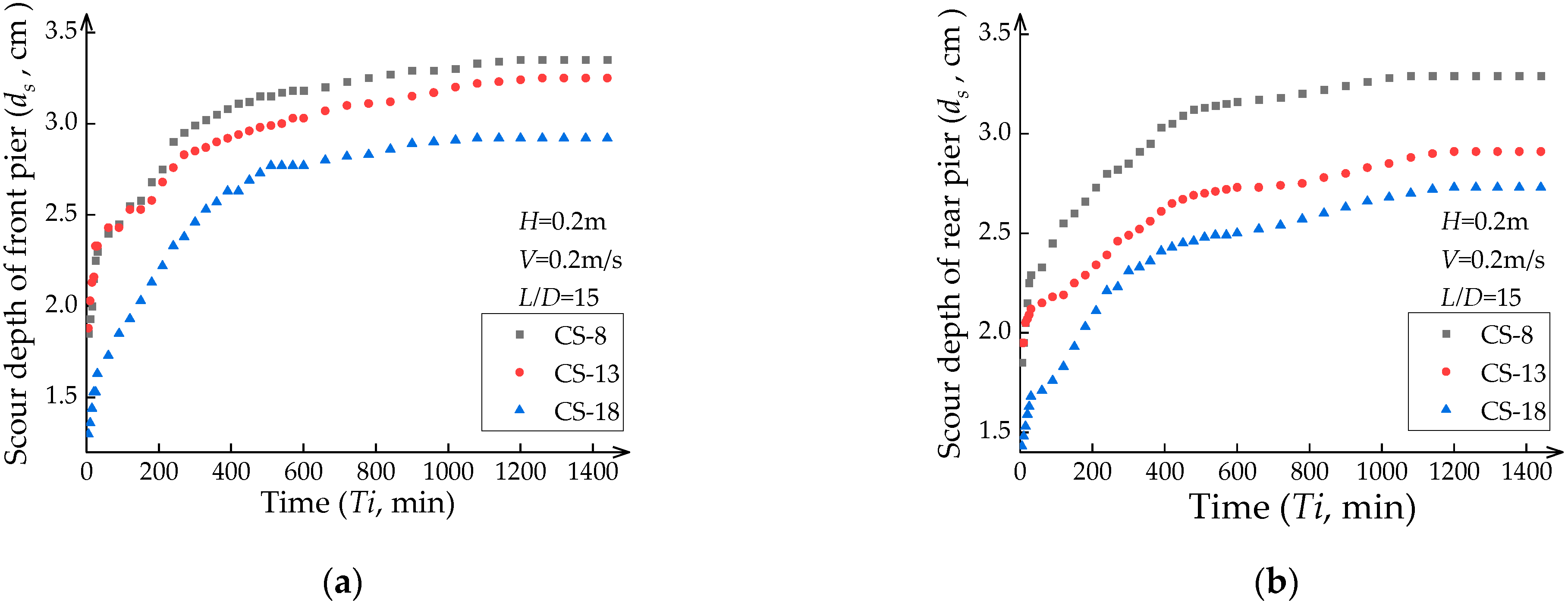
3.1. Process of Scour Depth over Time

The variation of scour depth at different cross sections of the bend flume under ice-covered flow conditions for both front and rear piers is illustrated in Figure 3. As observed from experiments, the scour holes developed rapidly within the first ten minutes. During this period, a significant amount of sediment particles has been transported downstream around the piers; subsequently, a deposition ridge of sediment particles has been formed between the piers as they were transported downstream. As the scour holes become deeper and wider, the strength of the horseshoe vortex gradually weakens, and the scour rate decreases accordingly.

3.2. Velocity Distribution Profiles at BACSs

Figure 4 shows the vertical distribution of streamwise velocity profiles located at 2 cm before each BACS’s front and rear pier. As shown in Figure 4, the flow velocity at each BACS of the S-shaped channel exhibits a gradually decreasing trend with the increase in the amount of the channel bend toward downstream (namely, one bend at CS-8, two bends at CS-13, and three bend at CS-18), indicating that as water flows through an S-shaped flume, its kinetic energy gradually diminishes. At each BACS, the streamwise velocity in front of the front pier is more than that of the rear pier due to the shading effect of the front pier on the rear pier and the consumption of a certain amount of energy from upstream to downstream.

3.3. Effect of Pier Spacing Distance on the Scour

Experimental results showed that the pier spacing distance is one important factor affecting the scour pattern around double piers in tandem arrangement. As shown in Figure 5, the length of scour holes in the vicinity of both front and rear piers increases with the pier spacing ratio for all BACSs (CS-8, CS-13 and CS-18). However, the scour hole length at both front and rear piers approaches a constant value at each BACS once the pier spacing ratio is L/D > 15. This means that, in the case of L/D < 15, the interaction of the front and rear pier affects the pattern of scour holes around piers. One can see from Figure 5, if L/D < 10, the closer these two piers are placed in the channel, the shorter the scour hole length around the rear pier. Furthermore, with the increase in channel bend from upstream toward downstream of the S-shaped channel, under the condition of the same L/D, the scour hole length around both front and rear piers in tandem arrangement becomes smaller.
One can see from Figure 5, either the front or the rear piers in a tandem arrangement, the scour hole length, which depends on the pier spacing distance, for the front or the rear piers, has the same increasing trend for all BACSs. BACS-8 has been chosen as the study cross-section for analyzing the development of scour holes around both front and rear piers with different pier spacing distances. For the flow condition with the water depth of H = 0.2 m and flow velocity of V = 0.2 m/s, contour diagrams for describing scour hole with varying pier spacing distance for CS-8 are presented in Figure 6. Results showed that the maximum depth and range of scour holes around the rear pier differ significantly from those at the front pier if L/D < 10. Due to sediment deposition between piers and shading effects from its counterpart, the size of scour holes around the rear pier is normally less than that of scour holes at the front pier. At BACS-8, the maximum depth (ds) and length (Ls) of scour holes around the rear pier are less than 84% of those at the front pier, while the width of scour holes (Ws) around the rear pier is about 95% or nearly the same as that at the front pier. At the front pier at BACS-13, the scour hole depth (ds) and length (Ls) at the rear pier are less than 83% of those at the front pier, while the scour hole width (Ws) is less than 80% of that at the front pier. Similarly, at the front pier at BACS-18, the scour hole depth (ds) and length (Ls) at the rear pier are less than 86% of those at the front pier, while the scour hole width (Ws) is less than 76% of that in the front pier. When L/D > 15, the depth (ds), length (Ls), and width (Ws) of scour holes at the rear pier at all bend sections are more than 90% of those of the front piers at BACSs, and the impact of the front pier on the rear pier diminishes. The maximum depth and range of scour holes around both front and rear piers remain stable at all BACS, and thus the scouring process around both front and rear piers can be regarded as a single pier scouring. This suggests that as the L/D value increases, the interaction between front and rear piers gradually decreases until a certain value is reached where the scour holes stabilize. However, in the straight channel, under the same hydraulic conditions, the maximum depth and range of scour holes around the rear pier differ significantly from those of the front pier when L/D < 9, and the local scour around the front pier has hardly influence on that around the rear pier when L/D ≥ 17 [30]. This difference between the bend and straight channels should be attributed to three dimensional in the curved channel. As Sui et al. (2008) claimed, two reverse transverse circulation cells exist in flow along a river bend under an ice cover, namely, one cell near the ice cover and the other near the riverbed. The direction of the transverse flow near the ice cover and channel bed generally goes towards the convex bank, whereas the flow between these two cells goes towards the concave bank [32]. Thus, the local process around piers in a bend channel will be affected.
Figure 7 illustrates the maximum depth of scour holes around double piers in a tandem arrangement in a straight channel compared to that at BACS of a bend under ice-covered flow conditions with varying pier spacing distance. The dashed line represents the corresponding scour depth for a single pier, while data regarding scour holes around double piers in a tandem arrangement in a straight channel from Sang et al. [30] is presented in Figure 7d. The comparison between the depth of scour hole at a single pier under an ice cover and that of the open flow condition reveals that the ice cover on the water surface increases the maximum depth of scour hole. It can be seen from Figure 7 that, by changing the pier spacing distance, the variation trend of the maximum depth of scour holes at the double piers in the tandem arrangement at BACS in the S-shaped bend flume is the same as that in the straight flume under an ice cover. The maximum depth of scour hole at the front pier of the double tandem piers exhibits fluctuations compared to that at a single pier, while the maximum depth of scour hole around the rear pier increases as the L/D increases. The maximum depth of scour hole at the front and rear piers at each BACS of the S-shaped flume exhibits a decreasing trend with the increase in the amount of channel bends toward downstream. From the profiles of the streamwise velocities in front of the piers (see Figure 4), after BACS, the scouring capacity of the flow around the pier decreases gradually downstream. With the increase in L/D, the rear pier experiences less shading effect caused by the front pier, resulting in an increasing trend of the maximum depth of scour hole at the rear pier. This suggests that the impact of the horseshoe-shaped vortex formed from the front pier on the rear pier decreases gradually as L/D increases. With the flow moving downstream in the bend channel, the closer to the pier at the downstream BACS position, the weaker the local scour.

3.4. Formule for Determining the Maximum Scour Depth

Considering all factors affecting the scouring process at piers in the bend channel under an ice cover, the following relationship between the dimensionless maximum depth of scour holes in the vicinity of piers and essential variables affecting scour depth has been developed:
F d s , D , ρ ,   ρ s , n i , n b ,   d 50 , L , V , H , g , α , β = 0
where, ds is the maximum depth of scour holes, D is the diameter of the bridge pier, L is the pier spacing distance, V is the initial approaching flow velocity, H is the initial approaching flow depth, g is the gravitational accelerated, ρ is the mass density of water, ρs is the mass density of sand, nb is the roughness coefficient of sand bed, ni is the roughness coefficient of ice cover, d50 is the median size of sand bed, α is the cumulative rotation angle of water flowing from CS-6 to where the bridge pier is located (for example, when the pier is located in CS-13, α = 150°), β is the angle of the bend where the piers are located (as can be seen from Figure 1, each bend has an angle of β = 100°).
By means of the dimensional analysis, the following equation is obtained for describing the maximum scour depth:
f ( d s D , F r , n i n b , ρ ρ s , d 50 D ,   L D , α β ) = 0
where, ds/D is the relative maximum scour depth, Fr is the Froude number, L/D is the pier spacing ratio, and α/β is the ratio for flow rotation (α/β). In this study, one sand is used as the bed material. Namely, both d50 and nb are assumed as constants. Also, only one model ice cover was used, ni is a constant. Thus, the following dimensionless variables can be considered as constants: (ρ/ρs), (d50/D) and (ni/nb). Thus, Equation (2) can be expressed as follows:
d s D = k F r a L D b α β c
where k, a, b and c are coefficients.
Based on data acquired from experiments, the regression equation for describing the maximum depth of scour holes around front piers under an ice cover has been derived as follows:
d s D = 3.447 F r 0.447 L D 0.034 α β 0.067
Similarly, the regression equation for describing the maximum depth of scour holes around rear piers under an ice cover has been derived as follows:
d s D = 0.954 F r 0.2 L D 0.306 α β 0.165
By using Equations (4) and (5), the calculated maximum depths of scour holes at both front and rear piers under an ice cover are compared to those of measurements and presented in Figure 8a,b, respectively. One can see from Figure 8a,b, the calculated maximum depths of scour holes around both front and rear piers are in good agreement with the laboratory results.
Figure 9 compares the calculated ds/D values (for different L/D values) to those of laboratory measurements for the same Fr with different α/β. It can be observed from Figure 9 that the dimensionless parameter ds/D increases with the increase of L/D under the same α/β and Fr. One can see that ds/D remains stable when the pier spacing ratio L/D > 15. Also, ds/D decreases with the increase of α/β under the same L/D and Fr, which means that the relative maximum scour depth (ds/D) around the tandem double piers at BACS in the bend channel decreases with the increase of the number of the bend that the flow passes.
From Equations (4) and (5), it can be seen that the Froude number Fr is positively correlated with the maximum depth of scour holes around both front and rear piers. Namely, the higher the Froude number, the deeper the scour holes around the piers. Furthermore, the pier spacing ratio (L/D) and the relative maximum scour depth (ds/D) are positively correlated, indicating that the relative maximum scour depth (ds/D) increases with the increase of pier spacing. The impact of the pier spacing ratio (L/D) on the maximum depth of scour holes at the front pier is much less than that for the rear pier, suggesting that the maximum depth of scour hole around the rear pier is substantially influenced by pier spacing distance. Results of this experimental study also showed that the relative maximum depth of scour holes (ds/D) exhibits a negative correlation with the current rotation ratio (α/β) (the ratio of the cumulative rotation angle of flowing current from the upstream control cross-section CS-3 to the location of the piers (α) to the bending angle of the channel (β)). This suggests that the relative maximum depth of scour holes (ds/D) gradually decreases as the flow moves further downstream from BACS. Certainly, this phenomenon doesn’t occur in a straight channel.

4. Conclusions

Based on experiments conducted in an S-shaped bend flume laboratory, a local scour process around double piers in a tandem arrangement under an ice cover has been studied. The following results are drawn:
(1)
The variation trend of the maximum depth of scour holes around the double piers in the tandem arrangement at BACS in an S-shaped bend flume is like that in a straight flume. However, when the pier spacing ratio (L/D) is between 3 and 10 in a bend channel, the maximum depth of scour holes and scour range around the rear pier are significantly different from those of the front pier, while this criteria for a straight channel is 2 < L/D < 9. When the pier spacing ratio (L/D) is greater than 15, the scour process around both the front and rear pier can be considered the scour process at a single pier. The maximum depths and ranges of scour holes around both front and rear piers are similar to those of a single pier, while this criteria for a straight channel is L/D > 17.
(2)
Under the same flow condition with the same pier spacing ratio and bed material, with the increase in the amount of channel bend from upstream toward downstream of the S-shaped channel, the maximum depth of scour holes at both the front pier and rear pier in tandem arrangement becomes smaller comparing to those in the upstream bend. Downstream of BACS, the scouring capacity of the flow around the pier decreases downstream. With the increase in pier spacing distance, the rear pier experiences less shading effect caused by the front pier, resulting in an increasing trend of maximum scour depth at the rear pier. By comparing the local scour around double piers in the tandem arrangement of an S-shaped bend channel under an open-flow condition to that under an ice-covered flow condition, it has been observed that the presence of an ice cover on water surface increased the depth of scour holes.
(3)
Based on the experiment data, the r equations describing the maximum depth of scour holes around both front and rear piers have been derived. The higher the Froude number Fr is, the deeper the scour holes around the piers. An increase in the pier spacing ratio (L/D) leads to an increase in the relative maximum scour depth (ds/D). The impact of the pier spacing ratio (L/D) on the maximum depth of scour holes at the front pier is much less than that for the rear pier. The relative maximum scour depth (ds/D) exhibits a negative correlation with the current rotation ratio (α/β). This suggests that, as the flow moves further downstream from BACS, the relative maximum scour depth (ds/D) gradually decreases. The results calculated using the proposed equations agree well with the laboratory results.

Author Contributions

Z.L.: Data curation, formal analysis, methodology, and writing—original draft preparation; J.W.: Conceptualization, supervision, methodology, funding acquisition, writing—original draft preparation; J.S.: Conceptualization, formal analysis, methodology, writing—review and editing; T.C.: Data curation, investigation; P.L.: Data curation, investigation; G.L.: Conceptualization, methodology. All authors have read and agreed to the published version of the manuscript.

Funding

This research was funded by Joint Funds of the National Natural Science Foundation of China, grant number U2243239 and the National Key Research and Development Program of China, grant number 2022YFC3202502. The authors are grateful for the assistance provided by the National Key Research and Development Program of China and the Joint Funds of the National Natural Science Foundation of China.

Data Availability Statement

The authors declare no conflict of interest.

Conflicts of Interest

The data are available in the case that it is required.

References

  1. Wang, J.; Shi, F.Y.; Chen, P.P.; Wu, P.; Sui, J. Impact of bridge pier on the stability of ice jam. J. Hydrodyn. 2015, 27, 865–871. [Google Scholar] [CrossRef]
  2. Sui, J.; Wang, J.; He, Y.; Krol, F. Velocity profiles and incipient motion of frazil particles under ice cover. Int. J. Sediment Res. 2010, 25, 39–51. [Google Scholar] [CrossRef]
  3. Beltaos, S.; Tang, P.; Rowsell, R. Ice jam modelling and field data collection for flood forecasting in the Saint John River, Canada. Hydrol. Process. 2012, 26, 2535–2545. [Google Scholar] [CrossRef]
  4. Sui, J.; Karney, B.W.; Fang, D. Variation in water level under ice-jammed condition–Field investigation and experimental study. Hydrol. Res. 2005, 36, 65–84. [Google Scholar] [CrossRef]
  5. Sui, J.; Wang, D.; Karney, B.W. Suspended sediment concentration and deformation of riverbed in a frazil jammed reach. Can. J. Civ. Eng. 2000, 27, 1120–1129. [Google Scholar]
  6. Wardhana, K.; Hadipriono, F.C. Analysis of recent bridge failures in the United States. J. Perform. Constr. Facil. 2003, 17, 144–150. [Google Scholar] [CrossRef] [Green Version]
  7. Sui, J.; Afzalimehr, H.; Samani, A.K.; Maherani, M. Clear-water scour around semi-elliptical abutments with armored beds. Int. J. Sediment Res. 2010, 25, 233–245. [Google Scholar] [CrossRef]
  8. Aksoy, A.O.; Bombar, G.; Arkis, T.; Guney, M.S. Study of the time-dependent clear water scour around circular bridge piers. J. Hydrol. Hydromech. 2017, 65, 26–34. [Google Scholar] [CrossRef] [Green Version]
  9. Yilmaz, M.; Yanmaz, A.M.; Koken, M. Clear-water scour evolution at dual bridge piers. Can. J. Civ. Eng. 2017, 44, 298–307. [Google Scholar] [CrossRef] [Green Version]
  10. Wang, H.; Tang, H.; Liu, Q.; Wang, Y. Local Scouring around Twin Bridge Piers in Open-Flume Flows. J. Hydraul. Eng. 2016, 142, 06016008. [Google Scholar] [CrossRef]
  11. Liu, Q.; Tang, H.; Wang, H.; Xiao, J. Critical velocities for local scour around twin piers in tandem. J. Hydrodyn. 2018, 30, 1165–1173. [Google Scholar] [CrossRef]
  12. Ghodsi, H.; Najafzadeh, M.; Khanjani, M.J.; Beheshti, A. Effects of Different Geometric Parameters of Complex Bridge Piers on Maximum Scour Depth: Experimental Study. J. Waterw. Port Coast. Ocean. Eng. 2021, 147, 04021021. [Google Scholar] [CrossRef]
  13. Kim, H.S.; Nabi, M.; Kimura, I.; Shimizu, Y. Numerical investigation of local scour at two adjacent cylinders. Adv. Water Resour. 2014, 70, 131–147. [Google Scholar] [CrossRef]
  14. Najafzadeh, M.; Barani, G.A. Experimental study of local scour around a vertical pier in cohesive soils. Sci. Iran. 2014, 21, 241–250. [Google Scholar]
  15. Zhou, K.; Duan, J.; Bombardelli, F.A. Experimental and Theoretical Study of Local Scour around Three-Pier Group. ASCE J. Hydraul. Eng. 2020, 146, 04020069. [Google Scholar] [CrossRef]
  16. Najafzadeh, M.; Oliveto, G. More reliable predictions of clear-water scour depth at pile groups by robust artificial intelligence techniques while preserving physical consistency. Soft Comput. 2021, 25, 5723–5746. [Google Scholar] [CrossRef]
  17. Bozkus, Z.; Ozalp, M.C.; Dincer, A.E. Effect of pier inclination angle on local scour depth around bridge pier groups. Arab. J. Sci. Eng. 2018, 43, 5413–5421. [Google Scholar] [CrossRef]
  18. Cheng, T.; Wang, J.; Chen, P.; Sui, J. Simulation of ice accumulation around bridge piers during river breakup periods using a discrete element model. J. Hydrodyn. 2022, 34, 94–105. [Google Scholar] [CrossRef]
  19. Wang, J.; Shi, F.; Chen, P.; Wu, P.; Sui, J. Simulations of ice jam thickness distribution in the transverse direction. J. Hydrodyn. 2014, 26, 762–769. [Google Scholar] [CrossRef]
  20. Wang, J.; Li, Z.; Cheng, T.; Sui, J. Time-dependent local scour around bridge piers under ice cover-an experimental study. Chin. J. Hydraul. Eng. 2021, 52, 1174–1182. [Google Scholar]
  21. Wang, J.; Sui, J.; Karney, W.K. Incipient Motion of Non-Cohesive Sediment Under Ice Cover–An Experimental Study. J. Hydrodyn. 2008, 20, 117–124. [Google Scholar] [CrossRef]
  22. Hu, H.; Wang, J.; Cheng, T.; Hou, Z.X.; Sui, J. Flume bed deformation and ice jam evolution around bridge piers. Water 2022, 14, 1766. [Google Scholar] [CrossRef]
  23. Wu, P.; Balachandar, R.; Sui, J. Local Scour around Bridge Piers under Ice-Covered Conditions. J. Hydraul. Eng. 2015, 142, 04015038. [Google Scholar] [CrossRef]
  24. Namaee, M.R.; Sui, J. Impact of armour layer on the depth of scour hole around side-by-side bridge piers under ice-covered flow condition. J. Hydrol. Hydromech. 2019, 67, 240–251. [Google Scholar] [CrossRef] [Green Version]
  25. Namaee, M.R.; Sui, J. Effects of ice cover on the incipient motion of bed material and shear stress around side-by-side bridge piers. Cold Reg. Sci. Technol. 2019, 165, 102811. [Google Scholar] [CrossRef]
  26. Namaee, M.R.; Sui, J. Local scour around two side-by-side cylindrical bridge piers under ice-covered condition. Int. J. Sediment Res. 2019, 34, 355–367. [Google Scholar] [CrossRef]
  27. Namaee, M.R.; Sui, J. Velocity profiles and turbulence intensities around side-by-side bridge piers under ice-covered flow condition. J. Hydrol. Hydromech. 2020, 68, 70–82. [Google Scholar] [CrossRef] [Green Version]
  28. Namaee, M.R.; Sui, J.; Wu, Y.S.; Linklater, N. Three-dimensional numerical simulation of local scour around circular side-by-side bridge piers with ice cover. Can. J. Civ. Eng. 2021, 48, 1335–1353. [Google Scholar] [CrossRef]
  29. Wang, T.; Wang, J.; Hu, H.; Sang, L. Experimental study on critical conditions for ice jam development around side-by-side piers. Chin. J. Hydraul. Eng. 2022, 53, 1262–1269. [Google Scholar]
  30. Sang, L.S.; Wang, J.; Cheng, T.J.; Hou, Z.X.; Sui, J. Local Scour around Tandem Double Piers under an Ice Cover. Water 2022, 14, 1168. [Google Scholar] [CrossRef]
  31. Chiew, Y.M. Local Scour at Bridge Piers. Ph.D. Thesis, Auckland University, Auckland, New Zealand, 1984. [Google Scholar]
  32. Sui, J.; Wang, J.; Balachandar, R.; Sun, Z.; Wang, D. Accumulation of frazil ice along a river bend. Can. J. Civ. Eng. 2008, 35, 158–169. [Google Scholar] [CrossRef]
Figure 1. The layout of the experiment facility. (a) Plan view of S-shaped flume; (b) Model pier layout.
Water 15 02568 g001
Figure 2. Distribution curve of sediment particles in the bed.
Water 15 02568 g002
Figure 3. Depth of scour holes versus time. (a) Front pier; (b) Rear pier. (H is the total flow depth, V is the flow velocity, and L/D is the ratio of pier spacing distance to pier diameter).
Water 15 02568 g003
Figure 4. Vertical distribution of stream-wise velocity in front of piers under ice-covered flow conditions. (H is the total flow depth, and Z is the distance from the channel bed to the measurement point, and L/D is the ratio of pier spacing distance to pier diameter).
Water 15 02568 g004
Figure 5. Dependence of scour hole length on the pier spacing ratio (L/D) at the front pier compared to that of the rear pier: (a) CS-8; (b) CS-13; (c) CS-18. (H is the total flow depth, V is the flow velocity).
Water 15 02568 g005
Figure 6. Contour maps of channel bed deformation around two piers in tandem arrangement with different pier spacing distances at BACS CS-8.
Water 15 02568 g006
Figure 7. Effect of the pier spacing ratio (L/D) on the relative depth of scour holes (ds/H). (a) BACS-8; (b) BACS-13; (c) BACS-18; (d) straight channel. (H is the total flow depth, V is the flow velocity).
Water 15 02568 g007
Figure 8. The calculated maximum depths of scour holes compared to those of laboratory experiments. (a) Front pier; (b) Rear pier.
Water 15 02568 g008
Figure 9. Variation of ds/D versus L/D for Fr = 0.143. Comparison of: calculated values with laboratory experiments. (a) Front pier; (b) Rear pier.
Water 15 02568 g009
Table 1. Conditions for experiments in the present study.
Serial NumberV (m/s)H (m)D (m)L (m)Serial NumberV (m/s)H (m)D (m)L (m)
A10.20.20.02B30.20.20.020.10
A20.20.20.02B40.20.20.020.20
A30.20.20.020.06B50.20.20.020.30
A40.20.20.020.10B60.20.20.020.40
A50.20.20.020.14C10.20.20.02
A60.20.20.020.20C20.20.20.02
A70.20.20.020.24C30.20.20.020.06
A80.20.20.020.25C40.20.20.020.10
A90.20.20.020.30C50.20.20.020.14
A100.20.20.020.40C60.20.20.020.20
A110.20.150.020.10C70.20.20.020.22
A120.20.150.020.20C80.20.20.020.24
A130.20.150.020.24C90.20.20.020.28
B10.20.20.02C100.20.20.020.30
B20.20.20.02C110.20.20.020.40
Note: Table 1 is categorized into three groups, A, B and C, based on conditions of bridge piers installed at CS-8, CS-13, and CS-18 of BACSs, respectively. Among them, A1, B1 and C1 represent single pier conditions at BACSs under open flow conditions. Meanwhile, A2, B2 and C2 denote single pier conditions at BACSs under the ice-covered condition. The remaining cases refer to double piers under an ice-covered flow condition in a tandem arrangement.
Disclaimer/Publisher’s Note: The statements, opinions and data contained in all publications are solely those of the individual author(s) and contributor(s) and not of MDPI and/or the editor(s). MDPI and/or the editor(s) disclaim responsibility for any injury to people or property resulting from any ideas, methods, instructions or products referred to in the content.

