Communication

Biofilm Reactor with Permeable Materials as Carriers Archives Better and More Stable Performance in Treatment of Slightly Polluted Water during Long-Term Operation

1
School of Environment, Guangdong Engineering Research Center of Water Treatment Processes and Materials, and Guangdong Key Laboratory of Environmental Pollution and Health, Jinan University, Guangzhou 510632, China
2
Shenzhen Water Group Co., Ltd., Shenzhen 518030, China
3
School of Energy and Building Environment, Guilin University of Aerospace Technology, Guilin 541004, China
*
Author to whom correspondence should be addressed.
Water 2023, 15(13), 2415; https://doi.org/10.3390/w15132415
Submission received: 19 May 2023 / Revised: 20 June 2023 / Accepted: 27 June 2023 / Published: 29 June 2023

Abstract

:
Biofilms in reactors usually grow on impermeable surfaces, and the mass transfer of nutrients in biofilms is mainly driven by diffusion, which is inefficient especially for thick biofilms. In this study, permeable materials (i.e., nylon meshes) were used as biocarriers in a biofilm reactor, and their performance was evaluated and compared with the commercial biocarriers (PE08 and PE10) used for treating slightly polluted water. The results indicate that the mesh-based bioreactor achieved complete nitrification faster than the commercial biocarriers, with a more stable and better effluent quality during long-term operation. At a two-hour hydraulic retention time, the average effluent ammonia (NH4+-N) and nitrite (NO2-N) concentrations during the stabilized phase were 0.97 ± 0.79 and 0.61 ± 0.32 mg-N, respectively, which are significantly lower than those with commercial carriers. The estimated specific surface area activities for the mesh, PE08, and PE10 carriers were 1620, 769, and 1300 mg-N/(m2·d)), respectively. The biofilms formed on the nylon mesh were porous, while they were compact and nonporous on the PE carriers. Water with substrates might pass through the porous biofilms formed on the meshes, which could enhance mass transfer and result in a better and more stable treatment performance.

1. Introduction

Biofilm-based water treatment technologies, which mainly rely on the attached microorganisms on the surface of biocarriers to degrade pollutants in wastewater [1], have been widely used in wastewater treatment since they enhance biomass retention and also increase the diversity for bioreactions and microbial communities [2,3,4,5]. Biofilm reactors can be divided into fixed bed biofilm reactors and moving bed biofilm reactors, both of which have been popularly used due to their merits, e.g., easy to implement, high treatment efficiency, high tolerance to loading fluctuation, extended sludge age, and small footprint [6,7,8,9]. Therefore, biofilm-based processes have been widely embedded in various wastewater treatment facilities, e.g., for enhancing denitrification in municipal wastewater treatment plants, improving anerobic ammonia-oxidizing bacteria growth in the anaerobic ammonia oxidation process [10,11,12,13], decolorizing dye-containing textile wastewater [14], terephthalic acid wastewater treatment [15], anaerobic digestion processes [16], removing petroleum hydrocarbons [17], removing ammonia and organics from slaughterhouse and aquaculture wastewater [18], and conventional nitrification processes [19].
Powder or granular activated carbon, ceramic materials, nonwoven materials, and plastics are materials that are widely used for biofilm carriers [20,21,22]. Due to their low density and high hardness, plastics have been the most commonly used materials for biofilm carriers [23]. In addition to developing novel materials for biofilm carriers, optimizing biocarrier design is another important research direction in the development of biofilm-based technologies [24]. Previous studies on biocarriers have mainly focused on improving the ease of microorganism attachment and growth and increasing the specific surface area, with the aim to shorten the startup time and increase biofilm retention [25]. In addition to biofilm concentration, the mass transfer in biofilms impacts the activity and reactor performance as well [26]. Currently, biofilms usually grow on impermeable surfaces. Oxygen, dissolved organics, ammonia, and other nutrients are transferred from the bulk solution to the biofilm surface and then inwards, mainly being driven by the diffusion process as a result of concentration gradients. However, the diffusion process is usually inefficient, especially for thick biofilms. For biofilms growing on permeable materials, water can pass through them from either side, especially under turbulent conditions resulting from aeration, which can create convective flows that will enhance species (e.g., oxygen, substrates, and nutrients) transport from the wastewater bulk solution towards the biofilm interior and result in better mass transfer efficiency than that by diffusion only. It is most likely that reactors with permeable materials as carriers could achieve a better and more stable treatment performance.
In this study, permeable materials, i.e., nylon meshes, were used as the biocarriers to build a biofilm reactor. Its performance during the startup period and long-term operation were evaluated and compared with other commercial biocarriers in the treatment of slightly polluted wastewater.

2. Materials and Methods

2.1. Biofilm Carrier Preparation

The monofilament (approximately 80 μm in diameter) woven nylon meshes with a pore size of approximately 100 μm (Figure 1) were used as the biocarriers for the growth of biofilms. The screens were tightly wrapped on a 10 cm × 15 cm × 1 cm stainless steel frame and both sides were open. Two other commercial polyethylene (PE) biocarriers, PE10 and PE08, were used for comparison in this study. PE10 had dimensions of 25 mm (diameter) × 4 mm (height). Each PE10 carrier had 64 voids, which had a cross-sectional area ranging from 0.031 to 0.068 cm2. PE08 had dimensions of 5 mm (diameter) × 10 mm (height), and each PE08 carrier only had 8 voids with a cross-sectional area of approximately 0.011 cm2.
As the biofilms grow, the uneven, solid surface of the PE carriers will be covered. Therefore, the actual effective surface area of the PE carriers is usually smaller than the advertised values. In this study, the surface area of the PE carriers was calculated by assuming their solid surface is flat. Thus, the total surface area (including the wall surface for all of the voids) for one PE08 or PE10 carrier was estimated to be about 639 mm2 or 2160 mm2. A container with a volume of 1 L can hold 1368 PE08 carriers or 228 PE10 carriers. Therefore, the specific surface area for PE08 and PE10 carriers was estimated to be 870 m2/m3 and 520 m2/m3, respectively. The pores of a nylon mesh are very tiny, and can be easily and quickly covered by biofilms. Therefore, the total surface area for the nylon meshes was estimated based on their size in this study. One stainless steel frame (10 cm × 15 cm × 1 cm) for the nylon meshes had a volume of 150 cm3 and a surface area of 600 cm2 (10 cm × 15 cm × 4 cm). Thus, the estimated specific surface area of the mesh carriers was approximately 400 m2/m3.

2.2. Biofilm Reactor Setup and Long-Term Test

Three biofilm reactors were set up, as shown in Figure 1, to evaluate the performance of the three biocarriers in the treatment of slightly polluted water, which contained a high ammonia concentration like aquaculture wastewater and urban black and odorous water. The biofilm reactors (20 cm × 10 cm × 25 cm, made of polymethyl methacrylate) had an effective working volume of approximately 4 L and the volume fraction for biocarriers was approximately 50%. In the mesh reactor, six mesh frames were installed and the distance between two frames was approximately 2.5 cm. The water level in the reactor was 20 cm to ensure all of the carriers submerged. The three biofilm reactors were used to treat the simulated slightly polluted water, which contained COD and ammonium concentrations of 30 mg/L and 30 mg-N/L, respectively. The COD and ammonium in the influent were provided by glucose and ammonium bicarbonate, respectively. In addition, trace elements were added into the influent with the formula described previously [27]. The reactors were operated under room temperature, at approximately 23 °C. The hydraulic retention time (HRT) was controlled to be about 2 h at an inflow rate of approximately 33.3 mL/min. Air was supplied by a fine bubble diffuser at the bottom of each reactor at a rate of about 1.0 L/min. Initially, most of the PE08 and PE10 carriers in the reactors were fluidized, while most of them became settled when biofilms were formed. The dissolved oxygen (DO) concentration in the reactors was above 4 mg/L and the pH was maintained at 7–8 using sodium carbonate. Analytical methods for determining the DO concentration and pH have been described previously [28]. During the tests, the detached biofilms flowed out of the system along with the effluent. The effluent’s COD, ammonium (NH4+-N), nitrite (NO2-N), and nitrate (NO3-N) concentrations were regularly measured using Hach test kits with a spectrophotometer (DR3900; Hach, Loveland, CO, USA) [29].
Figure 1. Biofilm reactor setup with different carriers: (a) PE08, (b) PE10, and (c) nylon mesh.
Water 15 02415 g001

2.3. Biofilm Morphology Observation by SEM

After their stable operation, the biofilms on the biocarriers were observed using scanning electron microscopy (SEM). The biofilm samples were dehydrated first and then coated with an aurum–platinum alloy by following the procedure provided in a previous study [30]. Finally, an S-4700 scanning electron microscope (Hitachi, Japan) was used to observe the samples.

2.4. Estimating the Surface Loading Rates and Specific Surface Area Activity

The surface area loading rates were calculated using Equation (1):
S A L R = A N L R avg × V T S A
where ANLRavg is the average ammonium loading rate (ANLR) (kg-N/(m3·d)), and TSA is the total surface area, which is 0.30, 0.87, and 0.52 m2 for the mesh, PE08, and PE10 biocarriers at a filling rate of 50%.
The specific surface area activity (SSAA, mg-N/(m2·d)), which assumes the surface area available for microbe growth, can be estimated using Equation (2):
S S A A = Q S 0 S S S A × R × V
where Q is the inflow rate (m3/d); S0 is the substrate concentration in the influent (mg-N/L); S is the substrate concentration in the effluent (mg-N/L); SSA is the specific surface area (m2/m3), which is 400, 870, and 520 m2/m3 for the mesh, PE08, and PE10 biocarriers; V is the reactor volume (m3); and R is the filling rate of the biocarriers in the reactors, which is 50% in the study.

3. Results and Discussion

3.1. Reactor Performance during Start-Up Period

Figure 2 depicts the effluent NH4+-N, NO2-N, and NO3-N concentrations of the three reactors equipped with different biocarriers during the 455 days of operation. In the start-up phase, the effluent NH4+-N concentration in the PE08 biofilm reactor decreased to below 1 mg-N/L after 26 days of operation, while the effluent NO2-N concentration fluctuated between 20 and 25 mg-N/L from the 23rd to the 120th day, and then decreased to approximately 1 mg-N/L after the 130th day. In the PE10 biofilm reactor, the effluent NH4+-N and NO2-N concentrations decreased to less than 1 mg-N/L after 40 and 105 days of operation, respectively. In the mesh-based biofilm reactor, however, the effluent NH4+-N and NO2-N concentrations were less than 1 mg-N/L starting from the 69th and 78th day, respectively. In addition, during the start-up period, the peak value of NO2 for the PE08 and PE10 biofilm reactor was as high as 20 mg-N/L or even more, while it was below 20 mg-N/L in the mesh-based biofilm reactor. During nitrification, ammonia is oxidized into nitrite by ammonia oxidizers, and then into nitrate by nitrite oxidizers [31]. These results, as shown in Figure 2, again indicate that the ammonia oxidizers grew faster than nitrite oxidizers in the biofilm reactors without the retention of suspended solids.
It is well known that a long start-up time is required due to the slow growth of nitrifiers, especially for nitrite oxidizers [32]. In this study, it took 113, 119, and 78 days for the biofilm reactors filled with PE08, PE10, and mesh biocarriers to achieve complete nitrification, suggesting that mesh biocarriers could shorten the start-up time even at a short HRT of 2 h without the retention of suspended solids. In another study, it took 84 days to initiate complete nitrification using a novel biocarrier [33]. Previous studies have shown that although PE is the most commonly used carrier for biofilm reactors [26], its high hydrophobicity and low surface energy limit the initial microbial cell attachment, which may be the reason for the longer start-up time [34].

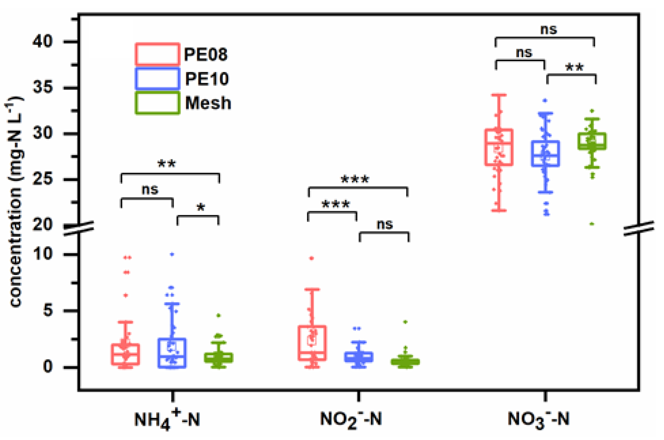
3.2. Reactor Performance under Stabilized Conditions

During the subsequent operation after start-up, the effluent nitrite in the PE08 biofilm reactor significantly fluctuated between 4 and 10 mg-N, while the effluent ammonia was more stable, ranging from 0.01 to 3.0 mg-N. In the PE10 biofilm reactor, the effluent ammonia fluctuated significantly between 0.1 and 10 mg-N/L, while the effluent nitrite was more stable, being generally less than 2 mg-N/L. However, both the effluent ammonia and nitrite were very stable in the mesh-based biofilm reactors. As shown in Figure 3, the average effluent ammonia concentration for the mesh biofilm reactor was 0.97 ± 0.79 mg/L, which was significantly (p < 0.05) lower than those in the PE08 (1.84 ± 2.18 mg/L) and PE10 (2.11 ± 3.07 mg/L) biofilm reactors. In addition, the average effluent nitrite concentration of the mesh biofilm reactor was 0.61 ± 0.56 mg-N/L, which was significantly (p < 0.01) lower than those in the PE08 (0.95 ± 0.66 mg/L) and PE10 (2.37 ± 2.09 mg/L) biofilm reactors. These results indicate that a better and more stable effluent quality was obtained in the biofilm reactor with mesh as the biocarrier.

3.3. SALR and SSAA for Different Biocarriers during Long-Term Tests

The surface area loading rates (SALR) and the specific surface area activity (SSAA) for the three biocarriers were calculated, with results shown in Figure 4. Due to the PE08 and PE10 biocarriers having a higher specific surface area, the estimated SALR for PE08 (828 mg-N/(m2·d)) and PE10 (1385 mg-N/(m2·d)) were lower than that (2400 mg-N/(m2·d)) in the mesh biofilm reactors. However, the mesh biofilm reactor had a better treatment performance, and its SSAA (1620 mg-N/(m2·d)) was significantly greater than those in the PE08 (769 mg-N/(m2·d)) and PE10 (1300 mg-N/(m2·d)) biocarriers. These results suggest that, although the mesh biocarriers had a lower specific surface area, they performed significantly better than the commercial biocarriers of PE08 and PE10.

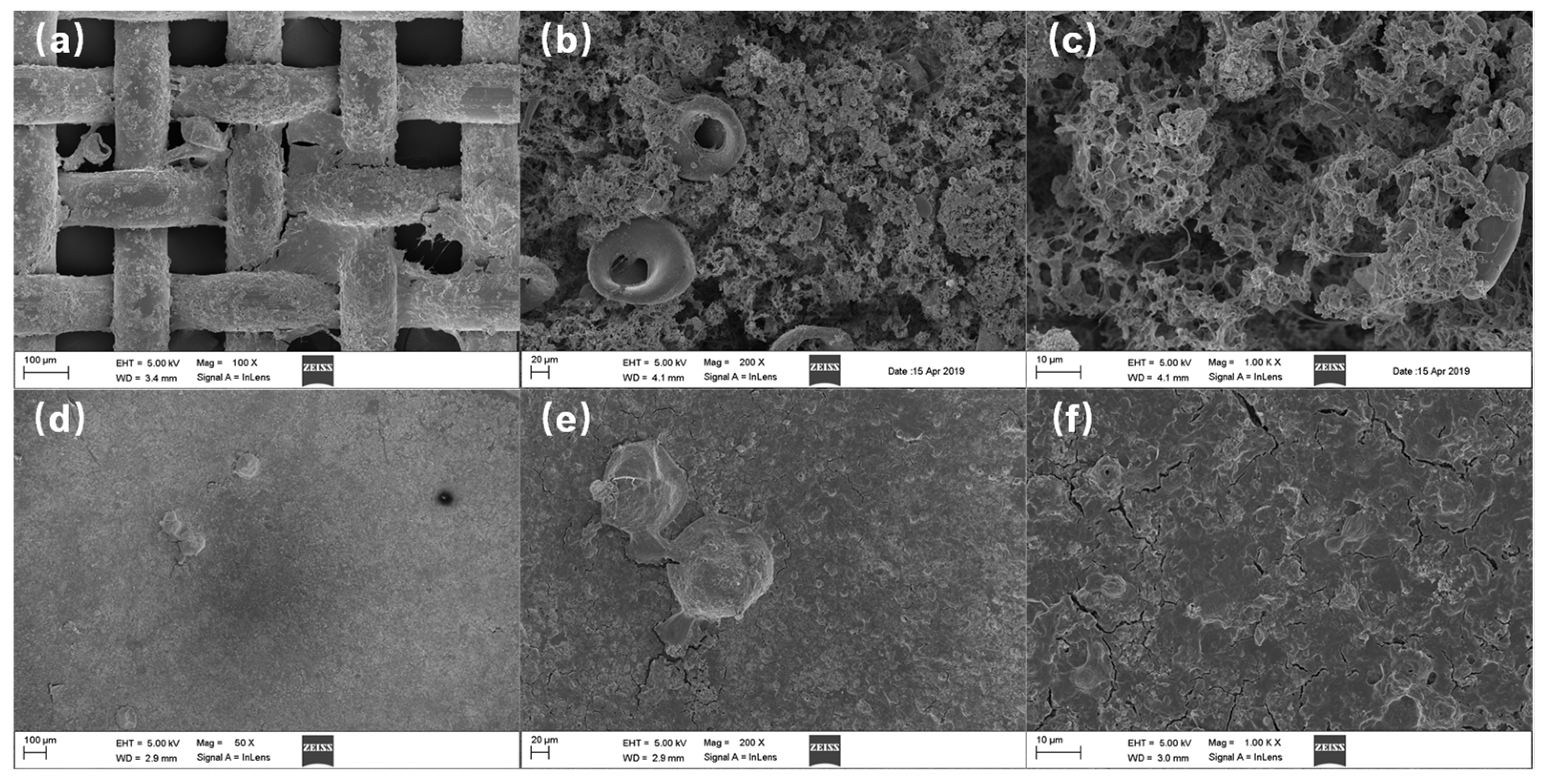
3.4. Biofilm Morphology Formed on Nylon Mesh and PE Carriers

As shown in Figure 5, the biofilms formed on the surface of the PE biocarrier are very compact without obvious pores. The biofilm cracks shown in Figure 5f might be caused by excessive dehydration prior to SEM analysis. After zooming in further on the image, it can be observed that bacterial cells were embedded in compact gel-like EPS. EPS refers to macromolecular polymers secreted by microorganisms, and mainly includes extracellular proteins, polysaccharides, and nucleic acids, which can accelerate the formation of biofilms. As shown in Figure 5b,c, however, porous and thick biofilm layers were formed on mesh-based carriers. A large number of microorganisms were observed in the biofilms. These results indicate that the biofilms formed on the PE carriers and permeable materials (i.e., nylon meshes) had significantly different structures. However, why the biofilms that formed on the permeable and impermeable materials had significantly different structures demands further studies.
Liquid diffusion and nutrient penetration through the biofilms are important factors affecting the overall treatment performance. Previous studies have suggested that thin and porous biofilms perform much better in terms of substrate transport even under normal operation conditions [35]. During a long-term operation, the initial advantages of fast biofilm growth and high microbial activity might be lost due to partial or complete blockage [36], particularly under a high organic load [9]. Desmond et al. (2018) found that the biofilms with compact and homogeneous structures had a higher hydraulic resistance, while those with a heterogeneous and porous structure had a lower hydraulic resistance [37]. Obviously, the biofilms with lower hydraulic resistance will have much better substrate transfer efficiency inside the biofilms. As shown in Figure 5b,c, the porous structure for the biofilms formed on the new biocarriers will allow water, oxygen, and substrates to pass through the biofilms easier, and then created a better environment for inner biofilm growth.

3.5. Proposed Mass Transfer in the Biofilms Formed on Permeable Materials

In biofilm reactors, biofilms usually grow on impermeable surfaces, i.e., dead-end biofilms (Figure 6a). Oxygen, dissolved organics, ammonia, and other nutrients are transferred from the bulk solution to the biofilm surface and then inwards to support biofilm growth [38]. When biofilms become thick, usually the inner biofilms will become inactive since oxygen and other electron acceptors are used up during the diffusion process from the surface to the interior [36,37,38,39,40,41]. As a result, the adhesions for the inner biofilms or those between the biofilms and solid surface become weak, leading to biofilm detachment. In biofilm reactors, biofilm detachments will impact treatment performance until fresh and active biofilms are formed again [42]. Therefore, the mass transfer in the biofilms is very important, as it not only impacts the treatment performance but also the activity of inner biofilms and biofilm detachment.
For the biofilms developed on the impermeable surface (i.e., dead-end biofilms), the mass transfer of nutrients in the biofilms is mainly driven by the diffusion process as the result of concentration gradients [43]. The differences in the concentration gradient, biofilm thickness, and inner structures will impact the diffusion efficiency [44]. Previous studies have shown that in aerobic systems, sufficient turbulence is created by aeration to control the turnover of microorganisms in biofilms, and then appropriate biofilm thickness is maintained by shear force [9]. As a result, the activity of biofilms and their effective mass transfer performance are maintained [9]. Our research showed that when permeable materials, e.g., meshes, are used as biocarriers, thick biofilms will be formed on both sides of the mesh and also inside the mesh pores (Figure 5). Since the mesh are thin and porous, water may pass through the biofilms from either side, especially under turbulent conditions resulting from aeration, creating convective flows that will bring species (e.g., oxygen, substrates, and nutrients) from bulk solutions to the biofilm interior and then result in greater mass transfer efficiency than that by diffusion only. These water-permeable biofilms that are formed on the meshes are shown in Figure 6b. The mesh pores can additionally provide more spaces for biofilm inhabitation, further enhancing the treatment efficiency. Moreover, after the biofilms form and grow inside the pores of PE08 and PE10, the contact area between biofilms and wastewater per unit carrier can be higher in the nylon meshes than in PE08 and PE10, which may be another reason for the better and more stable treatment performance of the mesh biofilm reactor.
This study demonstrated that the biofilm reactor with permeable materials (i.e., meshes) as carriers achieved a better and more stable effluent quality. However, more studies should be conducted to characterize the mass transfer performance and activities in biofilms formed on permeable surfaces (Figure 6b) and validate the proposed mechanisms.

4. Conclusions

The performance of a biofilm reactor with a nylon mesh as the biocarrier was evaluated and compared with other commercial biocarriers in the treatment of slightly polluted water. The mesh-based bioreactor achieved a faster start-up time and more stable and better effluent quality than the commercial biocarriers. The estimated specific surface area activities for the mesh, PE08, and PE10 carriers were 1620, 769, and 1300 mg-N/(m2·d)), respectively. On the permeable meshes, convective and porous biofilms formed and water with substrates passed through the mesh biofilms, which enhanced the mass transfer, and in turn, achieved a better and more stable treatment performance.

Author Contributions

Conceptualization, G.L.; investigation and methodology, Z.R., Z.L. and Y.Z.; writing—original draft preparation, Z.R. and Y.Z.; writing—review and editing, G.L. and X.L.; funding acquisition, G.L. and X.L. All authors have read and agreed to the published version of the manuscript.

Funding

This study was supported by a grant from the Guangxi Education Department (2022KY0797).

Data Availability Statement

Data used to support the findings of this study are available from the corresponding author upon request.

Conflicts of Interest

The funders had no role in the design of the study; in the collection, analyses, or interpretation of data; in the writing of the manuscript; or in the decision to publish the results.

References

  1. Ødegaard, H. Innovations in Wastewater Treatment: The Moving Bed Biofilm Process. Water Sci. Technol. 2006, 53, 17–33. [Google Scholar] [CrossRef] [PubMed]
  2. Al-Amshawee, S.; Yunus, M.Y.B.M.; Vo, D.-V.N.; Tran, N.H. Biocarriers for Biofilm Immobilization in Wastewater Treatments: A Review. Env. Chem. Lett. 2020, 18, 1925–1945. [Google Scholar] [CrossRef]
  3. Al-Amshawee, S.; Yunus, M.Y.B.M. Geometry of Biofilm Carriers: A Systematic Review Deciding the Best Shape and Pore Size. Groundw. Sustain. Dev. 2021, 12, 100520. [Google Scholar] [CrossRef]
  4. Zafarzadeh, A.; Bina, B.; Attar, H.; Nejad, M. Performance of moving bed biofilm reactors for biological nitrogen compounds removal from wastewater by partial nitrification-denitrification process. J. Environ. Health Sci. Eng. 2010, 7, 353–364. [Google Scholar]
  5. Koupaie, E.; Alavimoghadam, M. Comparison of overall performance between “Moving-bed” and “Conventional” sequencing batch reactor. J. Environ. Health Sci. Eng. 2011, 8, 235–244. [Google Scholar]
  6. Andreottola, G.; Foladori, P.; Ragazzi, M.; Tatàno, F. Experimental Comparison between MBBR and Activated Sludge System for the Treatment of Municipal Wastewater. Water Sci. Technol. 2000, 41, 375–382. [Google Scholar] [CrossRef]
  7. Barwal, A.; Chaudhary, R. To Study the Performance of Biocarriers in Moving Bed Biofilm Reactor (MBBR) Technology and Kinetics of Biofilm for Retrofitting the Existing Aerobic Treatment Systems: A Review. Rev. Env. Sci. Biotechnol. 2014, 13, 285–299. [Google Scholar] [CrossRef]
  8. Chu, L.; Wang, J.; Quan, F.; Xing, X.-H.; Tang, L.; Zhang, C. Modification of Polyurethane Foam Carriers and Application in a Moving Bed Biofilm Reactor. Process. Biochem. 2014, 49, 1979–1982. [Google Scholar] [CrossRef]
  9. di Biase, A.; Kowalski, M.S.; Devlin, T.R.; Oleszkiewicz, J.A. Moving Bed Biofilm Reactor Technology in Municipal Wastewater Treatment: A Review. J. Environ. Manag. 2019, 247, 849–866. [Google Scholar] [CrossRef]
  10. Flemming, H.-C.; Wingender, J.; Szewzyk, U.; Steinberg, P.; Rice, S.A.; Kjelleberg, S. Biofilms: An Emergent Form of Bacterial Life. Nat. Rev. Microbiol. 2016, 14, 563–575. [Google Scholar] [CrossRef]
  11. Morrison, G.M. The Social Status-Socioempathy Relationship among Mildly Handicapped and Nonhandicapped Children: Analysis of the Person × Environment Fit. Appl. Res. Ment. Retard. 1985, 6, 1–14. [Google Scholar] [CrossRef] [PubMed]
  12. Ødegaard, H. A Road-Map for Energy-Neutral Wastewater Treatment Plants of the Future Based on Compact Technologies (Including MBBR). Front. Environ. Sci. Eng. 2016, 10, 2. [Google Scholar] [CrossRef]
  13. Lemaire, R.; Zhao, H.; Thomson, C.; Christensson, M.; Piveteau, S.; Hemmingsen, S.; Veuillet, F.; Zozor, P.; Ochoa, J. Mainstream Deammonification with ANITATMMox Process. Proc. Water Environ. Fed. 2014, 6, 2183–2197. [Google Scholar] [CrossRef]
  14. Khelifi, E.; Gannoun, H.; Touhami, Y.; Bouallagui, H.; Hamdi, M. Aerobic Decolourization of the Indigo Dye-Containing Textile Wastewater Using Continuous Combined Bioreactors. J. Hazard. Mater. 2008, 152, 683–689. [Google Scholar] [CrossRef] [PubMed]
  15. Liu, J.; Zhou, J.; Xu, N.; He, A.; Xin, F.; Ma, J.; Fang, Y.; Zhang, W.; Liu, S.; Jiang, M.; et al. Performance Evaluation of a Lab-Scale Moving Bed Biofilm Reactor (MBBR) Using Polyethylene as Support Material in the Treatment of Wastewater Contaminated with Terephthalic Acid. Chemosphere 2019, 227, 117–123. [Google Scholar] [CrossRef]
  16. Martí-Herrero, J.; Alvarez, R.; Rojas, M.R.; Aliaga, L.; Céspedes, R.; Carbonell, J. Improvement through Low Cost Biofilm Carrier in Anaerobic Tubular Digestion in Cold Climate Regions. Bioresour. Technol. 2014, 167, 87–93. [Google Scholar] [CrossRef]
  17. Qaderi, F.; Sayahzadeh, A.H.; Azizi, M. Efficiency Optimization of Petroleum Wastewater Treatment by Using of Serial Moving Bed Biofilm Reactors. J. Clean. Prod. 2018, 192, 665–677. [Google Scholar] [CrossRef]
  18. McQuarrie, J.P.; Boltz, J.P. Moving Bed Biofilm Reactor Technology: Process Applications, Design, and Performance. Water Environ. Res. 2011, 83, 560–575. [Google Scholar] [CrossRef]
  19. Pastorelli, G.; Andreottola, G.; Canziani, R.; Darriulat, C.; de Fraja Frangipane, E.; Rozzi, A. Organic Carbon and Nitrogen Removal in Moving-Bed Biofilm Reactors. Water Sci. Technol. 1997, 35, 91–99. [Google Scholar] [CrossRef]
  20. Bouabidi, Z.B.; El-Naas, M.H.; Zhang, Z. Immobilization of Microbial Cells for the Biotreatment of Wastewater: A Review. Environ. Chem. Lett. 2019, 17, 241–257. [Google Scholar] [CrossRef]
  21. Peng, P.; Huang, H.; Ren, H.; Ma, H.; Lin, Y.; Geng, J.; Xu, K.; Zhang, Y.; Ding, L. Exogenous N-Acyl Homoserine Lactones Facilitate Microbial Adhesion of High Ammonia Nitrogen Wastewater on Biocarrier Surfaces. Sci. Total. Environ. 2018, 624, 1013–1022. [Google Scholar] [CrossRef]
  22. Wang, F.; Zhou, L.; Zhao, J. The Performance of Biocarrier Containing Zinc Nanoparticles in Biofilm Reactor for Treating Textile Wastewater. Process. Biochem. 2018, 74, 125–131. [Google Scholar] [CrossRef]
  23. Dong, Z.; Lu, M.; Huang, W.; Xu, X. Treatment of Oilfield Wastewater in Moving Bed Biofilm Reactors Using a Novel Suspended Ceramic Biocarrier. J. Hazard. Mater. 2011, 196, 123–130. [Google Scholar] [CrossRef] [PubMed]
  24. Ødegaard, H.; Gisvold, B.; Strickland, J. The Influence of Carrier Size and Shape in the Moving Bed Biofilm Process. Water Sci. Technol. 2000, 41, 383–391. [Google Scholar] [CrossRef]
  25. Accinelli, C.; Saccà, M.L.; Mencarelli, M.; Vicari, A. Application of Bioplastic Moving Bed Biofilm Carriers for the Removal of Synthetic Pollutants from Wastewater. Bioresour. Technol. 2012, 120, 180–186. [Google Scholar] [CrossRef]
  26. Wang, X.J.; Xia, S.Q.; Chen, L.; Zhao, J.F.; Renault, N.J.; Chovelon, J.M. Nutrients Removal from Municipal Wastewater by Chemical Precipitation in a Moving Bed Biofilm Reactor. Process. Biochem. 2006, 41, 824–828. [Google Scholar] [CrossRef]
  27. Liu, G.; Wang, J. Long-Term Low DO Enriches and Shifts Nitrifier Community in Activated Sludge. Environ. Sci. Technol. 2013, 47, 5109–5117. [Google Scholar] [CrossRef] [PubMed]
  28. Cai, D.; Huang, J.; Liu, G.; Li, M.; Yu, Y.; Meng, F. Effect of Support Material Pore Size on the Filtration Behavior of Dynamic Membrane Bioreactor. Bioresour. Technol. 2018, 255, 359–363. [Google Scholar] [CrossRef]
  29. Li, D.; Fang, F.; Liu, G. Efficient Nitrification and Low-Level N2O Emission in a Weakly Acidic Bioreactor at Low Dissolved-Oxygen Levels Are Due to Comammox. Appl. Environ. Microbiol. 2021, 87, e00154-21. [Google Scholar] [CrossRef]
  30. Lin, H.J.; Xie, K.; Mahendran, B.; Bagley, D.M.; Leung, K.T.; Liss, S.N.; Liao, B.Q. Sludge Properties and Their Effects on Membrane Fouling in Submerged Anaerobic Membrane Bioreactors (SAnMBRs). Water Res. 2009, 43, 3827–3837. [Google Scholar] [CrossRef]
  31. Focht, D.D.; Chang, A.C. Nitrification and Denitrification Processes Related to Waste Water Treatment. In Advances in Applied Microbiology; Perlman, D., Ed.; Academic Press: Cambridge, MA, USA, 1975; Volume 19, pp. 153–186. [Google Scholar]
  32. Rikmann, E.; Zekker, I.; Tenno, T.; Saluste, A.; Tenno, T. Inoculum-Free Start-up of Biofilm- and Sludge-Based Deammonification Systems in Pilot Scale. Int. J. Environ. Sci. Technol. 2018, 15, 133–148. [Google Scholar] [CrossRef]
  33. Massoompour, A.R.; Borghei, S.M.; Raie, M. Enhancement of Biological Nitrogen Removal Performance Using Novel Carriers Based on the Recycling of Waste Materials. Water Res. 2020, 170, 115340. [Google Scholar] [CrossRef]
  34. Khan, M.M.T.; Ista, L.K.; Lopez, G.P.; Schuler, A.J. Experimental and Theoretical Examination of Surface Energy and Adhesion of Nitrifying and Heterotrophic Bacteria Using Self-Assembled Monolayers. Environ. Sci. Technol. 2011, 45, 1055–1060. [Google Scholar] [CrossRef] [PubMed]
  35. Xavier, J.B.; Picioreanu, C.; Van Loosdrecht, M.C.M. A Framework for Multidimensional Modelling of Activity and Structure of Multispecies Biofilms. Environ. Microbiol. 2005, 7, 1085–1103. [Google Scholar] [CrossRef] [PubMed]
  36. Morgan-Sagastume, F. Biofilm Development, Activity and the Modification of Carrier Material Surface Properties in Moving-Bed Biofilm Reactors (MBBRs) for Wastewater Treatment. Crit. Rev. Environ. Sci. Technol. 2018, 48, 439–470. [Google Scholar] [CrossRef]
  37. Desmond, P.; Best, J.P.; Morgenroth, E.; Derlon, N. Linking Composition of Extracellular Polymeric Substances (EPS) to the Physical Structure and Hydraulic Resistance of Membrane Biofilms. Water Res. 2018, 132, 211–221. [Google Scholar] [CrossRef]
  38. Stewart, P.S. Diffusion in Biofilms. J. Bacteriol. 2003, 185, 1485–1491. [Google Scholar] [CrossRef] [PubMed] [Green Version]
  39. Boltz, J.P.; Daigger, G.T. Uncertainty in Bulk-Liquid Hydrodynamics and Biofilm Dynamics Creates Uncertainties in Biofilm Reactor Design. Water Sci. Technol. 2010, 61, 307–316. [Google Scholar] [CrossRef] [Green Version]
  40. Torresi, E.; Fowler, S.J.; Polesel, F.; Bester, K.; Andersen, H.R.; Smets, B.F.; Plósz, B.G.; Christensson, M. Biofilm Thickness Influences Biodiversity in Nitrifying MBBRs—Implications on Micropollutant Removal. Environ. Sci. Technol. 2016, 50, 9279–9288. [Google Scholar] [CrossRef] [Green Version]
  41. Mahendran, B.; Lishman, L.; Liss, S.N. Structural, Physicochemical and Microbial Properties of Flocs and Biofilms in Integrated Fixed-Film Activated Sludge (IFFAS) Systems. Water Res. 2012, 46, 5085–5101. [Google Scholar] [CrossRef]
  42. Zhu, L.; Yuan, H.; Shi, Z.; Deng, L.; Yu, Z.; Li, Y.; He, Q. Metagenomic Insights into the Effects of Various Biocarriers on Moving Bed Biofilm Reactors for Municipal Wastewater Treatment. Sci. Total. Environ. 2022, 813, 151904. [Google Scholar] [CrossRef] [PubMed]
  43. Taherzadeh, D.; Picioreanu, C.; Horn, H. Mass Transfer Enhancement in Moving Biofilm Structures. Biophys. J. 2012, 102, 1483–1492. [Google Scholar] [CrossRef] [PubMed] [Green Version]
  44. Jagaba, A.H.; Kutty, S.R.M.; Noor, A.; Birniwa, A.H.; Affam, A.C.; Lawal, I.M.; Kankia, M.U.; Kilaco, A.U. A Systematic Literature Review of Biocarriers: Central Elements for Biofilm Formation, Organic and Nutrients Removal in Sequencing Batch Biofilm Reactor. J. Water Process. Eng. 2021, 42, 102178. [Google Scholar] [CrossRef]
Figure 2. Effluent NH4+-N, NO2-N, and NO3-N concentrations during long-term operation in the biofilm reactors with carriers of (a) PE08, (b) PE10, and (c) mesh.
Water 15 02415 g002
Figure 3. The box plot of effluent NH4+-N, NO2-N, and NO3-N concentrations in the reactors with different biocarriers under stabilized conditions (ns = no significant differences; * indicates p < 0.05; ** indicates p < 0.01; *** indicates p < 0.001).
Water 15 02415 g003
Figure 4. Surface area loading rates (SALR) and specific surface area activity (SSAA) for different biocarriers during long-term tests.
Water 15 02415 g004
Figure 5. Scanning electron microscopy analysis of different biocarriers: (a) nylon mesh (having pore size of approximately 100 μm) with biofilm scraped; (b,c) biofilms formed on the nylon mesh biocarriers; (df) biofilms formed on the side surface of commercial polyethylene (PE) biocarriers.
Water 15 02415 g005
Figure 6. (a) The schematic for the mass transfer in the biofilms formed on the impermeable surface; (b) the proposed schematic for the mass transfer in the biofilms formed on the permeable surface (i.e., nylon meshes).
Water 15 02415 g006
Disclaimer/Publisher’s Note: The statements, opinions and data contained in all publications are solely those of the individual author(s) and contributor(s) and not of MDPI and/or the editor(s). MDPI and/or the editor(s) disclaim responsibility for any injury to people or property resulting from any ideas, methods, instructions or products referred to in the content.

