1. Introduction
Coal mining has a long history in China. Previously, due to the backward mining methods and technologies, some small coal mines used roadway and room pillar methods to excavate the upper coal seams at will to facilitate mining and control roof, resulting in a large number of mined-out areas [
1,
2,
3,
4]. Due to the lack of historical management accounts, these mined-out areas threatened the safe mining of coal mines greatly. To maximize the recovery of resources in the background of current coal resource consolidation, there is a need to adopt the downward mining method to re-mine the lower coal seam [
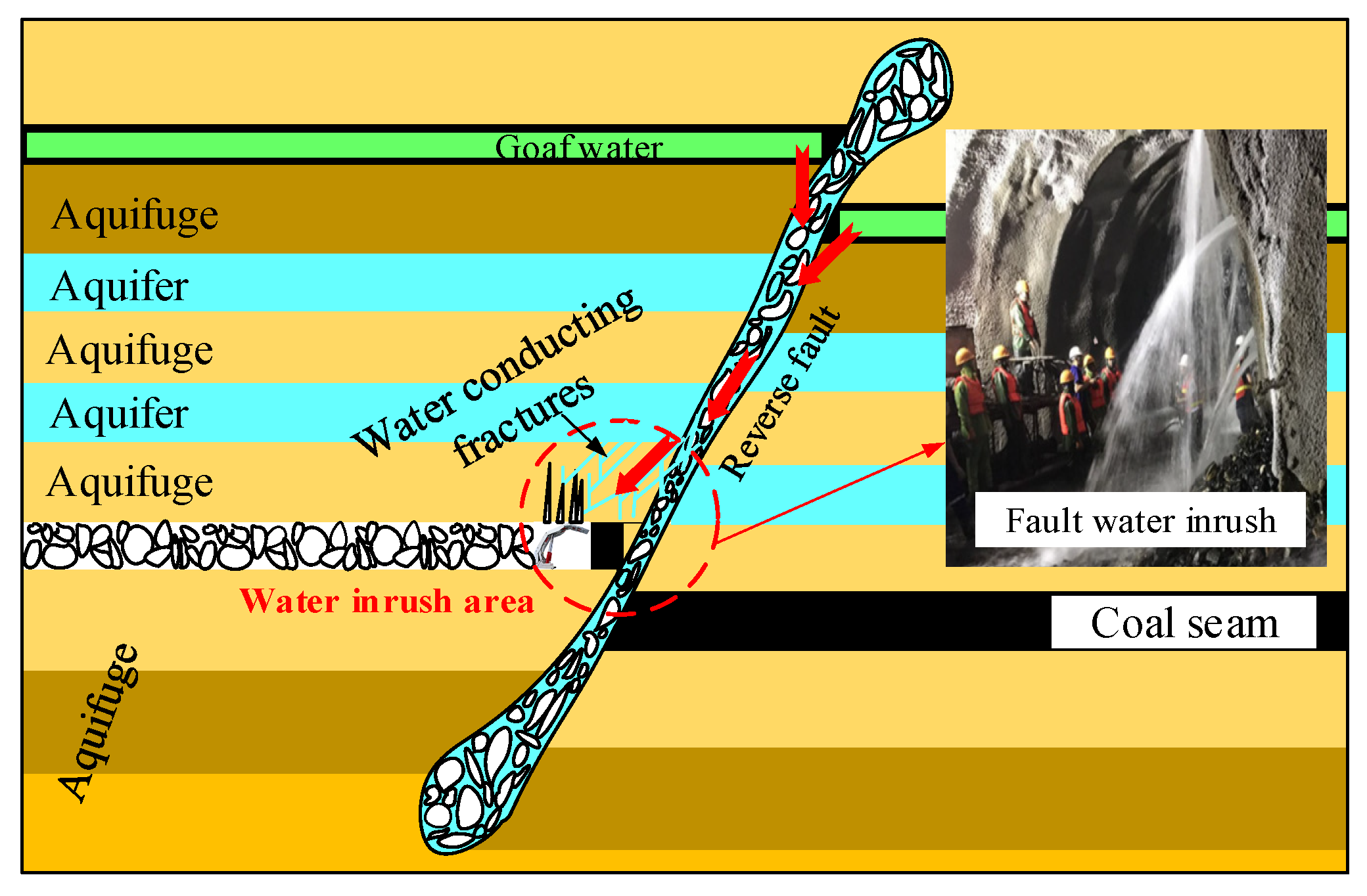
4]. The water inrush disasters are induced easily on account of the mining activity of lower coal destroying the rocks between coal seams and communicating the goaf water, especially when there are fault structures between coal seams (
Figure 1) [
5,
6,
7]. It was demonstrated that water inrush disaster caused by fault structures account for a considerable proportion [
8,
9].
The impact of fault on coal mining under water bodies is mainly reflected in the height of the fractured water-conducting zone (FWCZ) near the fault increasing significantly, and which is more likely to cause water inrush accident [
10,
11,
12]. Under the combined action of mining pressure and water pressure, the fault is activated by dislocation and fractures that are produced, which provide important conditions for water inrush channels [
13,
14,
15]. The existence of a fault changes the complete continuity of rock strata, and makes the fractures failure process of rock strata different from that of continuous rock masses [
16,
17,
18]. Under the influence of the fault, the supporting capacity of surrounding rock masses to the overburden strata is reduced, resulting in the height of the FWCZ at fault being higher than that in other places [
19,
20].
The fault Is activated easily under the influence of mining, and the rock masses are broken within the fault and its influencing areas [
21,
22]. Generally, fault protection pillar will be reserved in working face to avoid the influence when encountering a fault with large drop [
23]. However, there are still some problems: (1) fault activation will lead to roof water inrush disaster irreversibly if the width of reserved coal pillar is too small; (2) the height of the FWCZ in the working face will not increase due to the influence of fault if the width of the reversed coal pillar is large enough, but the coal pillar will cause the loss of coal resources [
24]. At the same time, many scholars conduct their research from many different angles, and yielded many results [
25,
26,
27,
28]. Therefore, the evaluate of the influence of fault on the breaking law of stope roof and the height of the FWCZ when working face crossing reverse fault has vital significance.
Some scholars studied the mechanism of water inrush from faults from different perspectives and achieved some research results. Huang [
11] simulated the dynamic fracture process of overlying strata, mining-induced stress and fissure of roof reversed fault in the working face for advancing form lower plate to upper plate. Zhang [
29] used UDEC software to simulate the movement and failure process of overlaying strata in the goaf at different dip angles and different horizontal fault distances, and the influence of faults on the failure, permeability of faults on the failure and permeability of overlaying strata in goaf was analyzed. The above research mainly focused on the factors affecting the stress evolution of rock layers, and there is insufficient understanding of the impact characteristics of fault activation on the migration and failure of overlying strata in goaf under the influence of mining.
With that in mind, the 15,103 working face of Wenzhuang Coal Mine were taken as a typical example in this paper, the height of the FWCZ in overburden strata was judged in this paper through engineering analogy methods, e.g., drilling fluid leakage method and drilling television method, the method of numerical simulation analysis was then used to study overlying strata failure height after mining of 15,103 working face through F6 reverse fault from the hanging wall to the footwall, providing a theoretical support for the prevention of goaf water disaster and to protect the ecological environment around the Wenzhuang Coal Mine. The research results can provide reference for the safe mining of passing through reverse faults under the influence of roof goaf water.
2. Geology and Hydrology of the Study Area
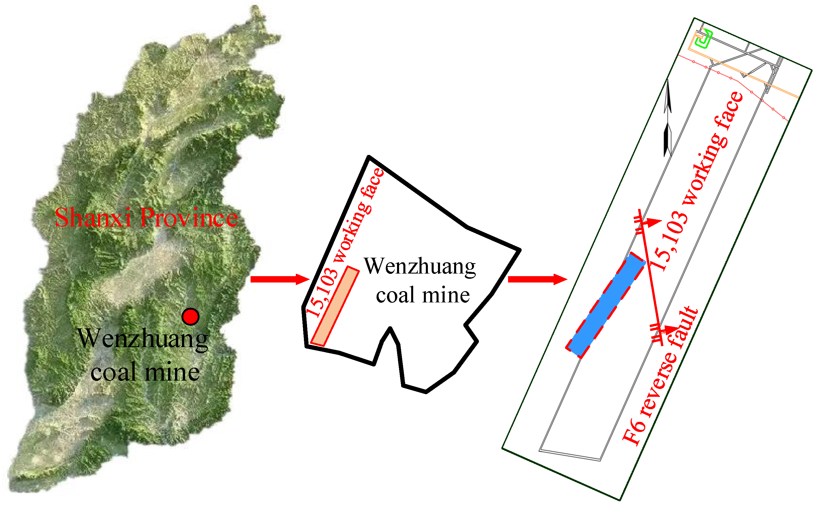
The Wenzhuang Coal Mine is situated in Wuxiang County, Shanxi Province, China, with a mining area of 9.94 km
2, which is subordinate to Shanxi Lu’an Mining Group Co., Ltd. (
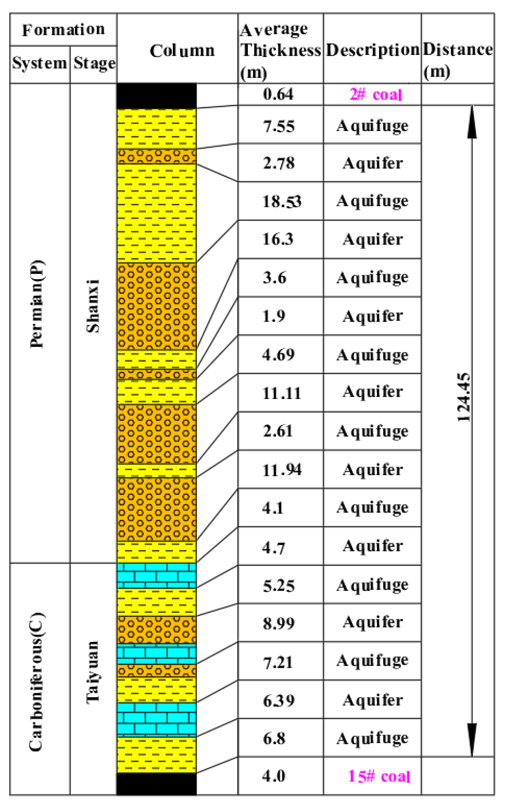
Figure 2). The method of strike longwall retreating full-mechanized mining was adopted. No. 2 Coal seam was located in the middle strata of Shanxi formation, the coal thickness was 0 to 1.59 m, with an average of 0.64 m, and the coal seam floor was mostly mudstone, sandy mudstone and fine sandstone. No. 15 Coal seam was located in the middle and upper part of the first section of Taiyuan formation, and the coal thickness was 3.08 to 4.91 m, with an average of 4.0 m, the coal seam roof was mainly composed of sandy mudstone, mudstone and siltstone. The aquifers between No. 2 and 15 coal seams were sandstone fractured aquifers of Shanxi formation with the characteristics of poor supply conditions and weak water yield, and limestone karst fractured aquifer of Taiyuan formation with the characteristic of weak water yield. There were stable aquifers dominated by argillaceous rocks between the aquifers, which can play a good role of interval water (
Figure 3).
The 15,103 working face was located in the west of No. 15 coal seam, with an elevation of +750 to +838 m (National Height Datum 1985), the corresponding ground elevation was +1015 to +1130 m. A goaf of No. 2 coal seam was about 120 m in the heading directly above it. It showed that there was ponding in the goaf by transient electromagnetic method. In addition, there was a F6 reverse fault in 15,103 working face, which strikes NW and dips NE, and whose maximum fault throw was 3.7 m. It was necessary to investigate the influence of F6 reverse fault on the height of the FWCZ, and whether goaf water will threaten the safe mining of the 15,103 working face through the FWCZ.
3. Analysis of the Mining-Induced Fracture
3.1. The Floor Failure Depth (FFD) of No. 2 Coal Seam
The rock layers of floor will move and failure occurs within a certain range after coal seam mining [
30]. The range of floor damage is related to the mining range and the distribution of support pressure around the goaf. The FFD caused by mining can generally be determined using an empirical formula and the plastic mechanics method [
31,
32,
33]. Here, the results obtained by these two methods are presented separately.
3.1.1. Empirical Formula Method
There are usually three empirical formulas for calculating the FFD of a working face, which are [
33]:
where H, α and L are the buried depth of the coal seam, the angle of the coal seam and the length of the working face, respectively, taking 137 m, 10°, 82 m for H, α and L according to site condition. To ensure safety, the maximum value of h
1, h
2 and h
3 was 10.29 m, as the FFD.
3.1.2. Plastic Mechanics Method
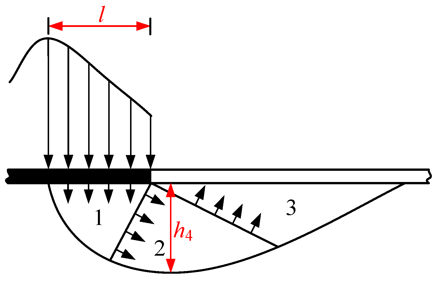
The FFD caused by mining can generally be determined using the calculation method of foundation in soil mechanics. According to the plasticity theory, the limited equilibrium area in the foundation is divided into three zones, namely active stress zone, transition zone and passive stress zone (the numeric symbols, 1, 2 and 3 in
Figure 4), respectively. The following calculation formula can be obtained [
33]:
Table 1 shows calculation parameters measured by a laboratory test and site conditions. The maximum FFD can be obtained by Equation (4): h
4 = 7.82 m. Comparing the FFD obtained from the above two calculation methods, 10.29 m was taken as the value of FFD of No. 2 coal seam for safety reasons.
3.2. The Height of the FWCZ of No. 15 Coal Seam
At present, the height of the FWCZ is always investigated with empirical formula, underground borehole observation and geophysical method [
30,
34,
35,
36,
37,
38]. Next, the height of the
FWCZ is calculated using the above three methods.
According to the literature, the lithology of the overburden rock stratum of No. 15 coal seam is medium hard. The empirical calculation formula for the height of the FWCZ under medium hard overburden conditions is as follows [
36,
39,
40]:
where
hl1,
hl2 are the height of the
FWCZ, m;
m is the average mining height, m.
According to Equations (5) and (6), the range of the height of the FWCZ of 15,103 working face was 46.56 to 90 m. Therefore, water injection leakage within this area should be observed specially when the underground observation is adopted.
3.2.1. Detection of Borehole Segmented Liquid Injection System
The borehole leakage method is a new approach to observe the height of the FWCZ by using the drilling device with double-head water-stopped machine function, which can either observe the FWCZ by upward-inclined drillhole above the goaf, or by downward-inclined borehole in the special roadway that was excavated above the coal seam. The application of the borehole leakage method has certain advantages according to the mining conditions of Wenzhuang Coal Mine.
- (1)
Observation scheme
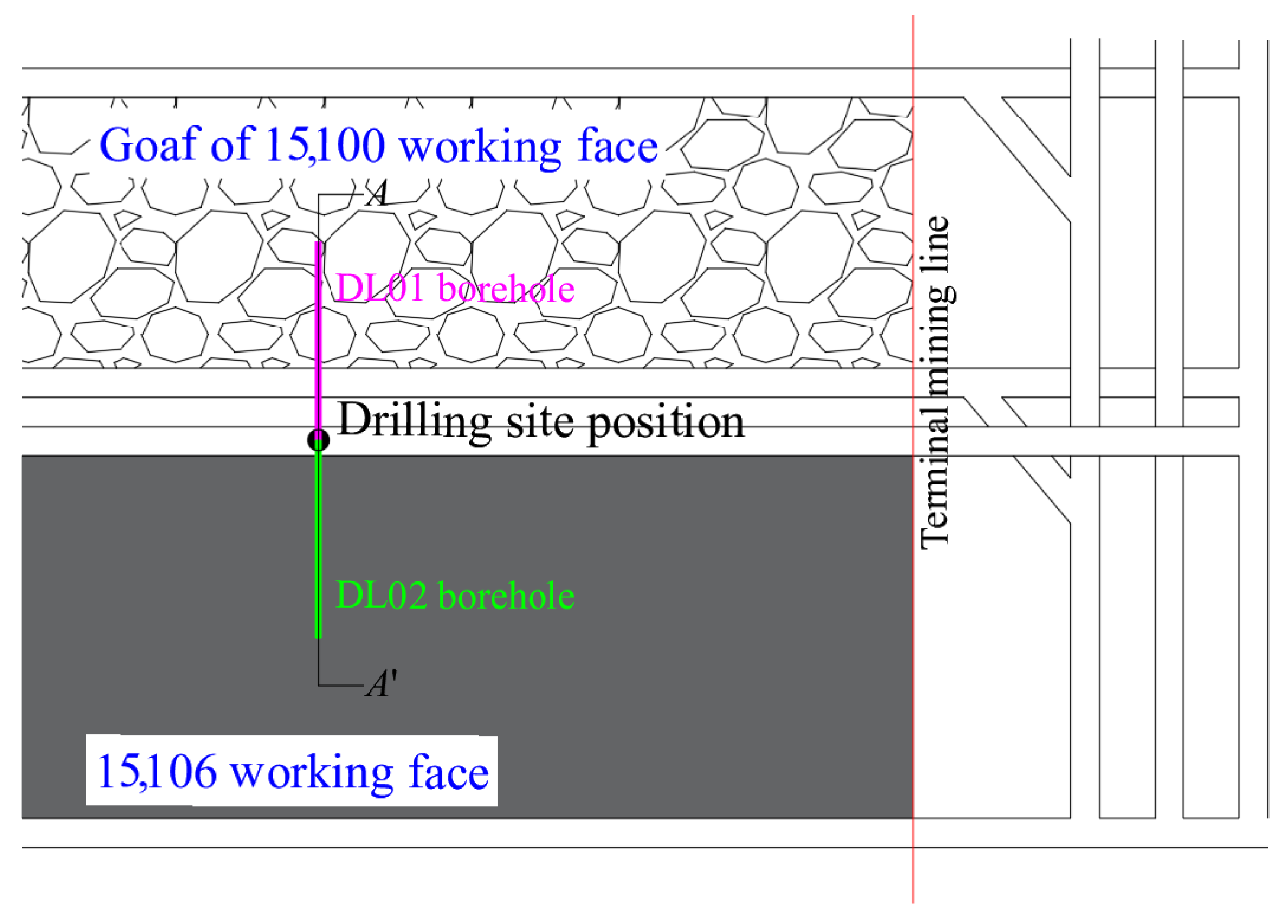
To increase the contrast between the boreholes, opening position of the two boreholes all arranged in ventilation roadway 770 m away from terminal mining line in working face 15,106. Among them, DL01 and DL02 boreholes were observation and comparison boreholes, respectively. The location of the drilling site and parameters is shown in
Figure 5 and listed in
Table 2, respectively. The lithology and hydrological conditions of each drill pipe passing through was recorded in detail in the process of drilling, and the whole drilling hole was sketched.
- (2)
Observation process
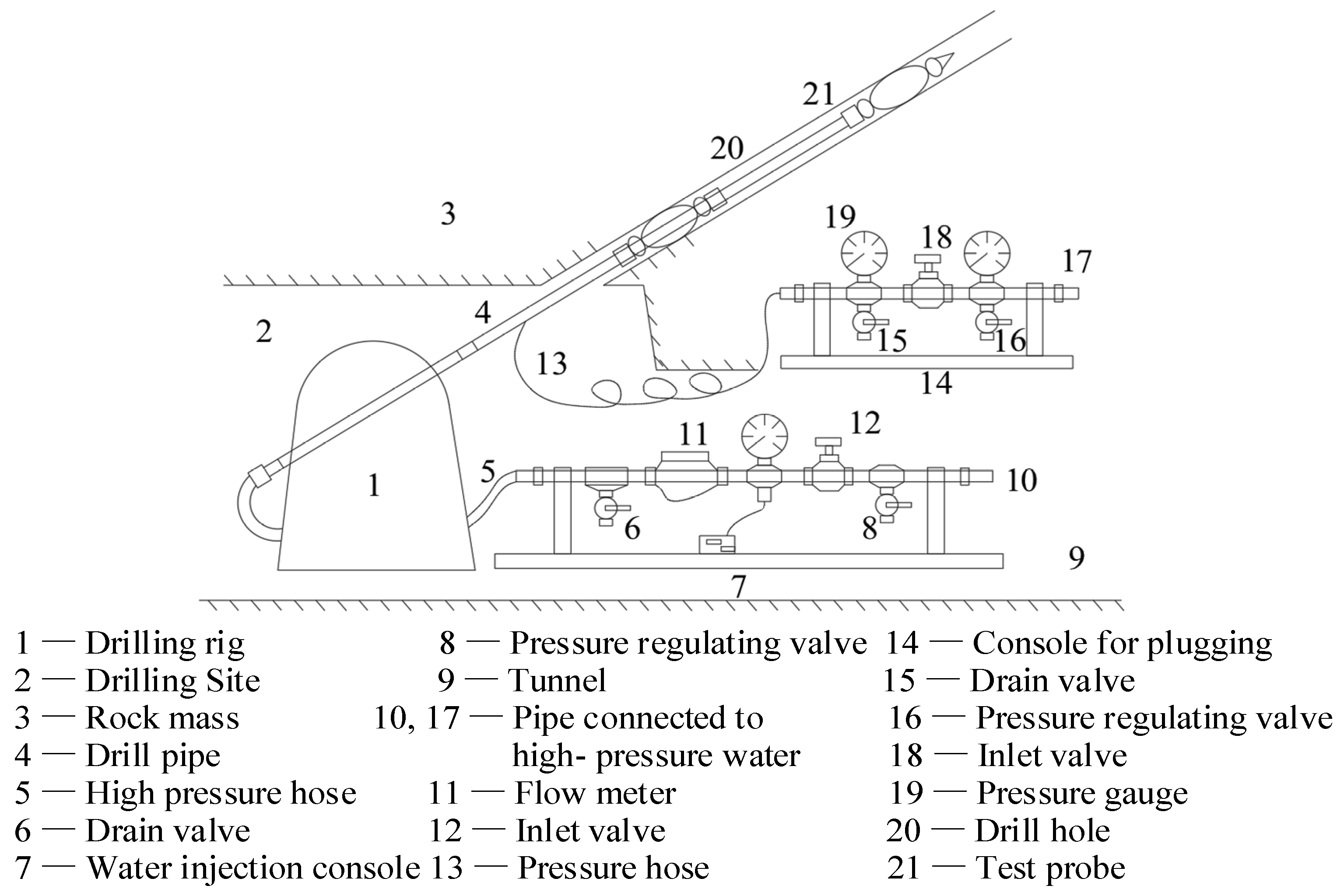
A self-designed double-head water-stopped machine was used to monitor the water injection leakage of boreholes before and after mining, and determined the distribution of fractures in each rock stratum after mining. The system was mainly composed of test probe, drilling rig, pressure hose, observation platform, etc. The simplified diagram of observation equipment is shown in
Figure 6.
The observation process is described as follows: (1) All parts of the equipment were assembled before observation to ensure that all interfaces were well sealed, and the water-plugging device was then pushed to the observation position through the drilling rig. (2) During observation, injected water into the capsule to make the sealing pressure reached 1.8 MPa and completed the plugging of the drilling section, then water was injected into the drill pipe to keep the injection pressure at 1.2 MPa. If the water injection flow and leakage reached a dynamic balance, the water injection volume in unit minute was measured through the flow meter, that is, the leakage. (3) After observation, the drain valve of capsule was opened to unload the pressure, water in the hole section was then discharged with the contraction of the capsule. (4) The above steps were repeated until the observation was achieved.
- (3)
Observation results
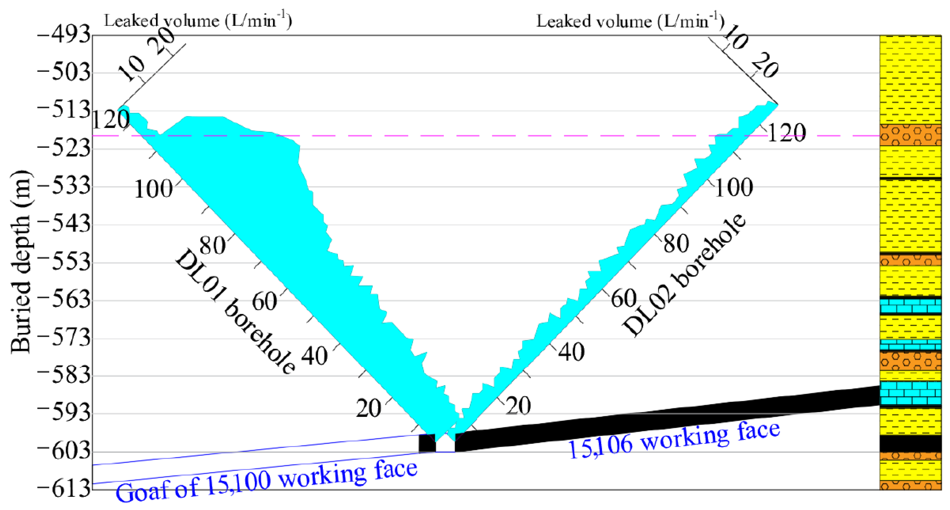
According to the above observation scheme, DL01 and DL02 boreholes were observed on 14 January 2021. The water injection leakage data observed in each borehole and the column shape of nearby borehole were drawn into
Figure 7 to analyze the change of water injection leakage in the borehole section and, finally, determine the height of water diversion fracture zone.
Figure 7 is the distribution map of water injection leakage in DL01, DL02 boreholes. As we can see from
Figure 7, the average change of water injection flow in DL02 borehole was 3.32 L/min, indicating that rock stratum has the characteristics of small permeability.
For DL01 borehole, the water injection leakage was in the range of 1.6–3.8 L/min within the drilling depth of 115–125 m (the vertical height was 82–90 m), which showed that the rock stratum in this section was not damaged compared with DL01 borehole. Nevertheless, the water injection leakage was in the range of 12.0–28.5 L/min within the drilling depth of 85–115 m (the vertical height was 61–82 m), indicating that the borehole penetrated the FWCZ at this time, for the water seepage of the rock stratum increased significantly. The rock stratum in this area was affected by mining to produce secondary fracture, and the water conductivity of rock stratum was relatively stronger. The rock stratum corresponding to the position of the FWCZ was medium sandstone, which were 85 m high from the coal seam.
3.2.2. Detection of Borehole TV
- (1)
Observation equipment
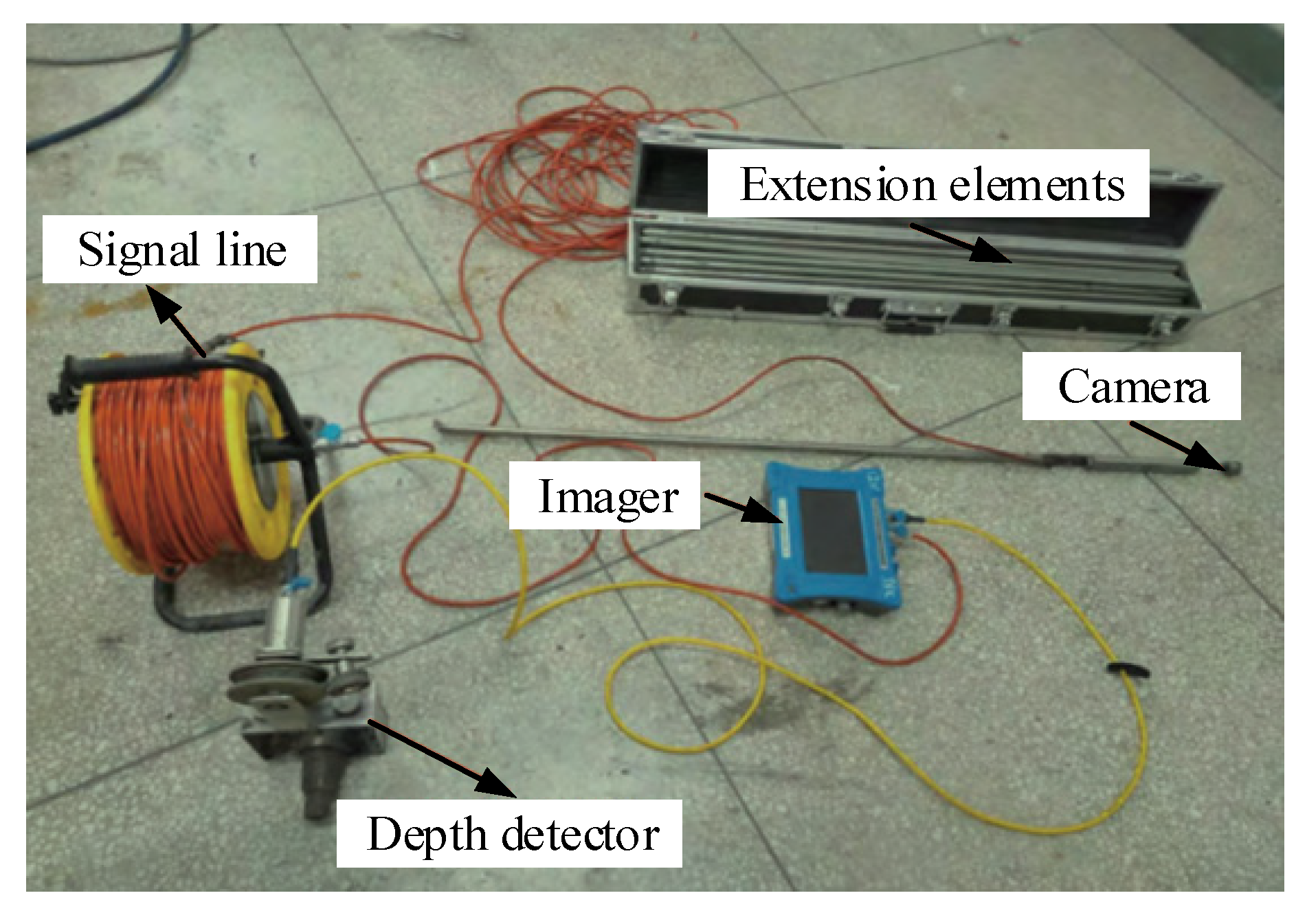
The downhole TV system is an observation system used for internal imaging of borehole, which includes a camera, an imager, extension elements, a signal line, etc. The geological structure in the borehole can be directly observed on the monitor by placing a waterproof camera with its own light source into the underground borehole. It can be used to identify lithology, fractures, cavities, weak interbeds and other conditions according to the shape, color, brightness and other information of the image.
Figure 8 shows the borehole TV developed by Gude Technology Company (Wuhan, China).
- (2)
Analysis on the observation results
On 14 January 2021, DL01 borehole was observed by builders with the borehole TV. The borehole depth of field observation was 125 m, of which the first 10 m included the borehole casing, and the actual effective observation depth was 115 m.
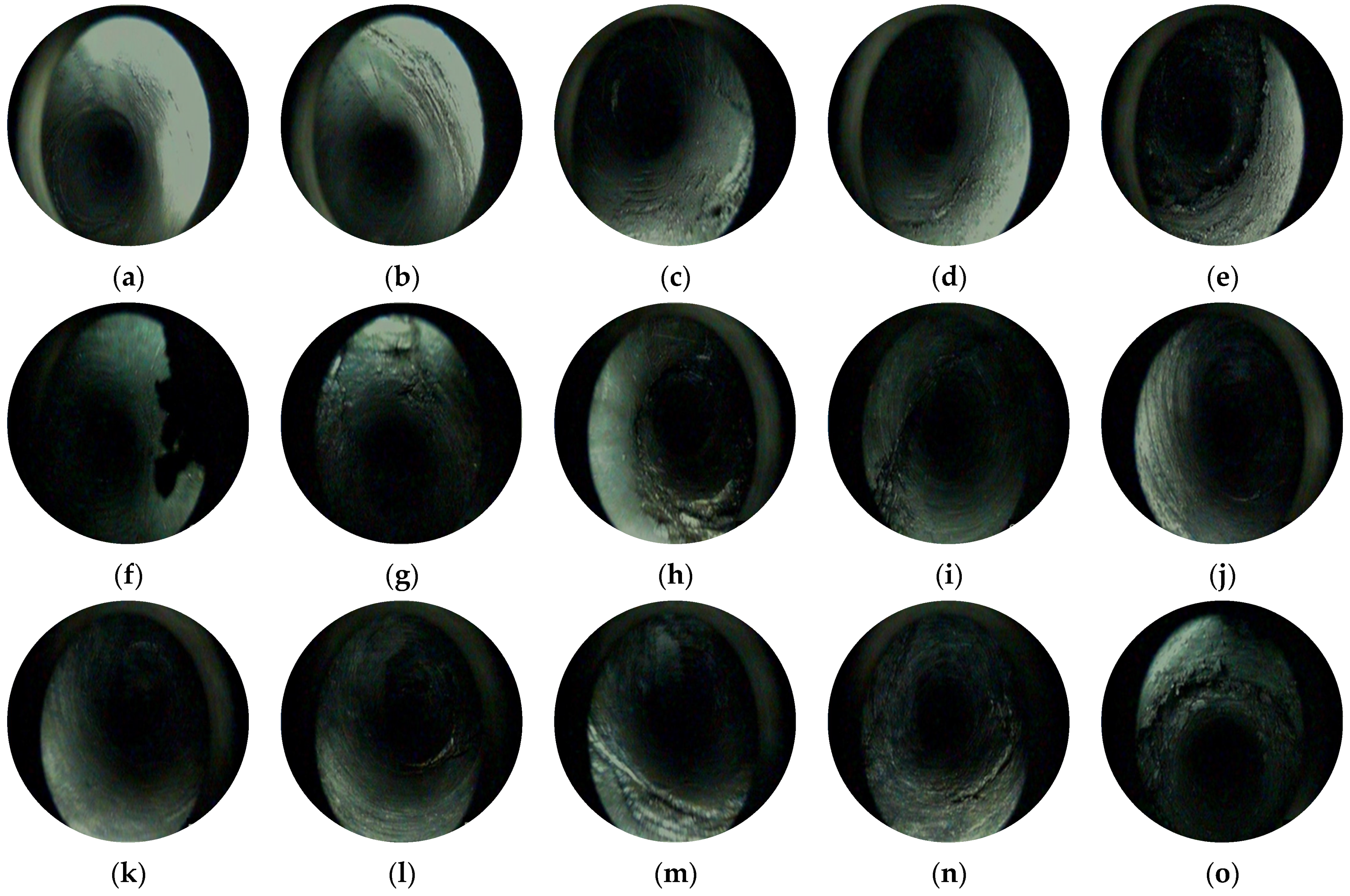
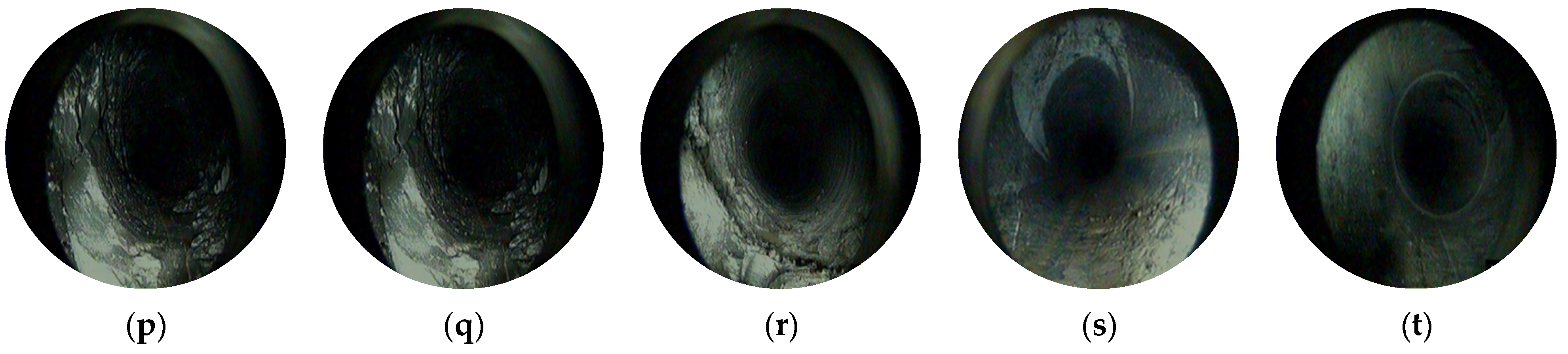
Figure 9 shows 20 representative photos of the development of overlying rock fractures through the DL01 borehole. The numbers behind the figure number were the vertical distances between the coal seam roof and this location.
According to the on-site observation records, there were no obvious fractures in the overlying rock within the vertical depth range of 3.21–12.27 m from No. 15 coal seam (
Figure 9a–c), indicating that the borehole section within this range did not yet enter the area of FWCZ. Obvious mining fractures began to appear in the overlying rock starting from the vertical depth of 15.42 m from No. 15 coal seam (
Figure 9d–g), indicating that the rock strata within this range were significantly affected by mining, but the width and number of fractures were relatively small. At the vertical depth of 32.89 m from No. 15 coal seam (
Figure 9h), the rock layer was severely damaged and the rock blocks were broken, which indicated that should be the overlying rock caving zone. As the vertical depth of No. 15 coal seam increased (
Figure 9i), the degree of overlying rock failure significantly decreased and showed a certain regularity. Fractures intersect longitudinally or layer wise, indicating that the borehole passed through the overlying rock caving zone. Further increasing the drilling depth (
Figure 9j–m), the identification of fracture direction and width increased, with oblique fractures being the main trend and showing obvious regularity. As the distance from No. 15 coal seam increased, the overlying rock fractures decreased, as shown in
Figure 9n–q. At the vertical depth of 85.39 m from No. 15 coal seam (
Figure 9r), the fractures completely disappeared (
Figure 9s,t), indicating the height of the FWCZ was 85.39 m. The height of the caving zone and the FWCZ observed through borehole television were 32.89 m and 85.39 m, respectively, and the caving/mining ratio and fractures/mining ratio were 8.2 and 21.3, respectively. This was consistent with the height of the FWCZ determined by the borehole leakage method.
4. Spatial Distribution of F6 Reverse Fault
Due to the lack of perfect geological data during the time that No. 2 coal seam was mining, the very existence of F6 reverse fault in No. 2 coal seam was uncertain.
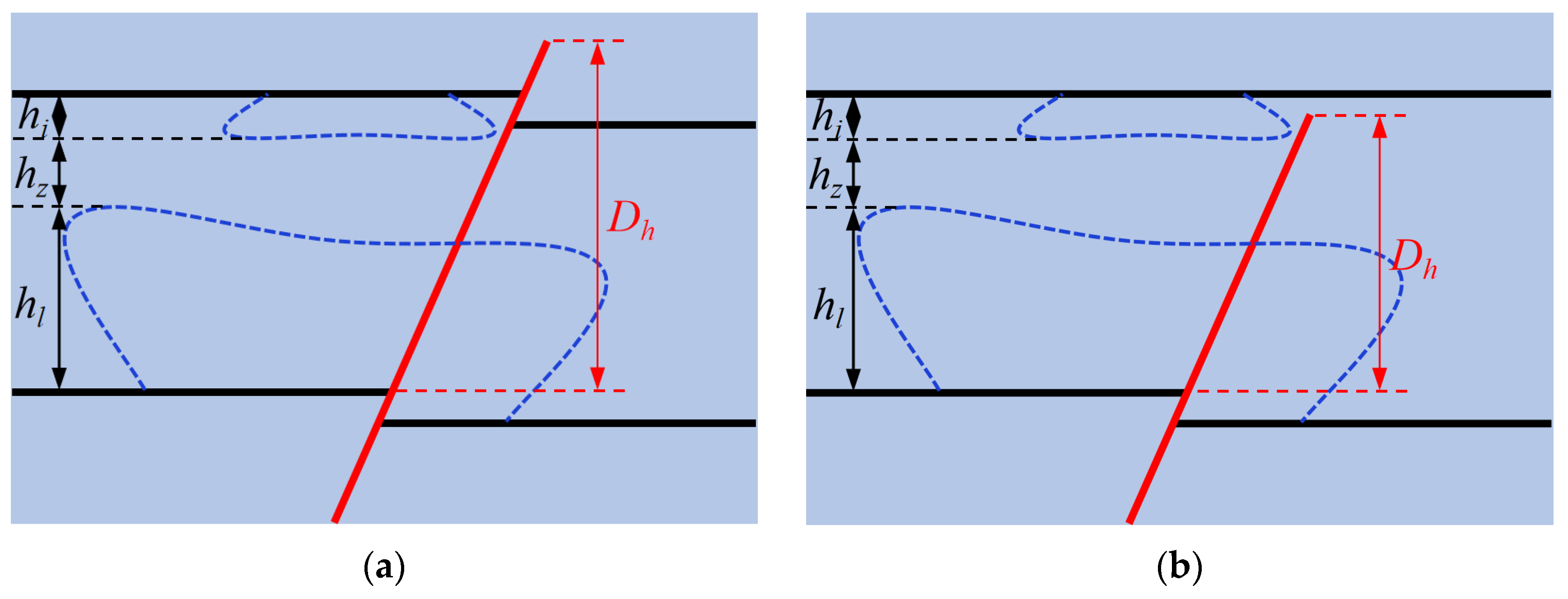
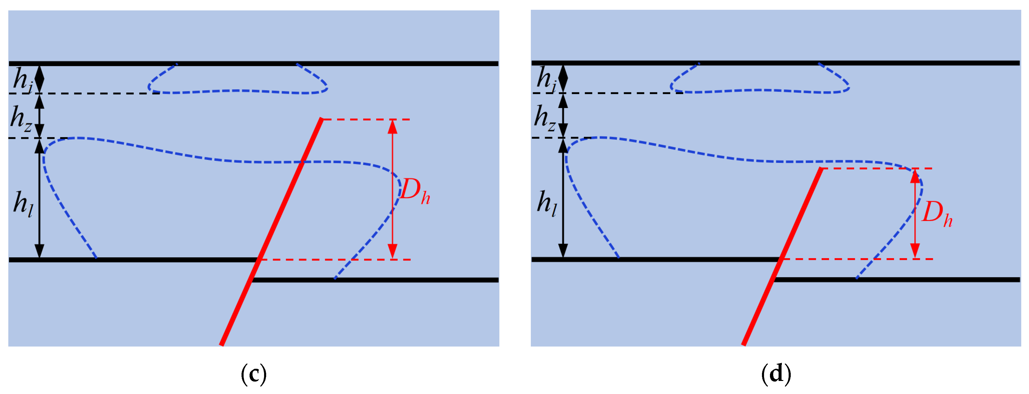
Figure 10 shows the four space relationships between F6 reverse fault and the mining-induced fractures, as follows:
(a) If
Dh ≥
hi +
hz +
hl (
Figure 10a), it means that F6 reverse fault cuts through the rock strata between No. 2 and 15 coal seams completely, then the FFD of No. 2 coal seam will be deepened along the fault zone, and also the height of the FWCZ of working face 15,103 will be increased due to fault activation. As a result, the goaf water of working face 2071 flows downward along the fracture into the 15,103 working face.
(b) If
hz +
hl ≤
Dh <
hi +
hz +
hl (
Figure 10b), it means that the rock strata between No. 2 and 15 coal seams are not cut through completely by F6 reverse fault, the goaf water of 2071 working face may then flow slowly downward along the fractures and F6 reverse fault, and then enter the 15,103 working face in the form of dripping and drenching.
(c) If
hl <
Dh <
hz +
hl (
Figure 10c), the goaf water of 2071 working face cannot enter the 15,103 working face, according to the prediction results of the height of the FWCZ in the 15,103 working face.
(d) If
Dh ≤
hl (
Figure 10d), F6 reverse fault has no effect on the FWCZ of the 15,103 working face, that is, the height of FWCZ is the same as that without fault. Intact curved rock strata between the FWCZ of the 15,103 working face and the floor failure area of 2071 working face had enough thickness to play the role of water-resistance.
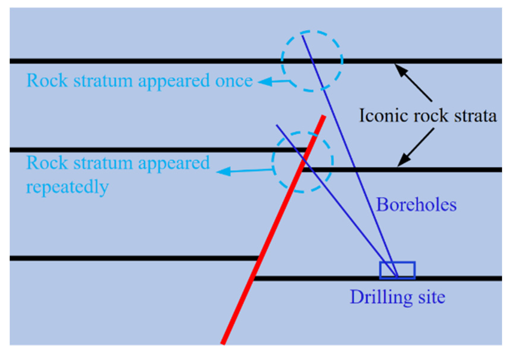
The drilling method was adopted to explore the cut through degree of F6 reverse fault in the overburden strata of the 15,103 working face, which can provide a basis for the prevention of goaf water disaster. The designed boreholes were constructed from the footwall to the hanging wall of F6 reverse fault. If the iconic rock stratum was cut through by the fault, its exposure will appear repeatedly in the borehole; otherwise, it will not (
Figure 11). No. 8 coal seam was 70 m above the 15,103 working face, the distance was less than the height of the FWCZ (85.39 m). If No. 8 coal seam was cut through by F6 reverse fault, it will appear repeatedly in the borehole. Therefore, No. 8 coal seam can be used as the iconic rock stratum for analyzing the cut through degree of F6 reverse fault.
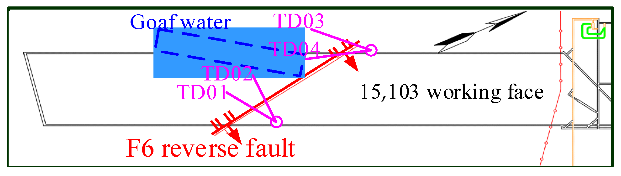
Four boreholes were constructed from the footwall to the hanging wall of F6 fault in return-air roadway and haulage roadway of the 15,103 working face.
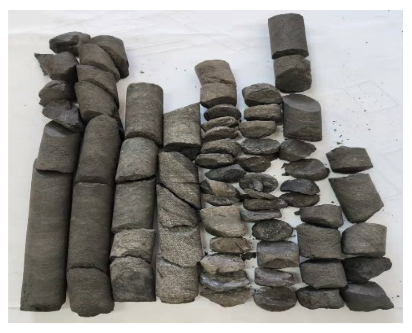
Figure 12 and
Figure 13 show the boreholes position and the photo of rock core specimens near No. 8 coal seam exposed by TD01 borehole, respectively. It can be seen that the No. 8 coal seam and its roof and floor rock-layers exposed were not repeated, nor were there fault planes and broken rock masses. Therefore, the No. 8 coal seam was not cut through by F6 reverse fault.
To make further verification of the rock stratum where F6 reverse fault disappeared in the overburden strata of No. 15 coal seam, K4 limestone, 34.64 m above No. 15 coal seam, was regarded as the iconic rock stratum to detect F6 reverse fault. The detection results also showed that K4 limestone was not repeated, nor were there fault planes and broken rock masses, indicating that K4 limestone was not cut through by F6 reverse fault. It can be seen that the disturbance range of F6 reverse fault was generally within the caving zone of the 15,103 working face from the above analysis (
Figure 10d); it is on account of the hanging wall of F6 reverse fault had weak cutting ability and released small amounts of energy in the process of being formed, and the total thickness of rock strata cut was small.
5. Numerical Simulation Analysis
Based on the geological and mining conditions of the 15,103 working face in Wenzhuang Coal Mine, to test the rationality of the above analysis, the failure form of overburden strata and the height of the FWCZ during mining were analyzed using the numerical simulation method.
5.1. Numerical Simulation Model
The overburden failure law during mining of the 15,103 working face was simulated through FLAC
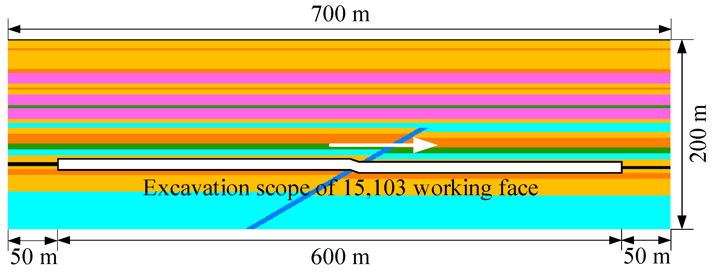
3D numerical simulation software. The established model is shown in
Figure 14 and the size was 700 m × 1 m × 200 m (length × width × height). The two sides and bottom of the model were fixed boundaries, and the top was free boundary. Mohr–Coulomb yielding criterion was adopted in the excavation simulation [
35]. The length of the working face in advancing direction was 600 m in
Figure 14. To reduce the boundary effect, coal pillars 50 m wide were intentionally left on both sides of the working face.
In accordance with a previous study [
28], an initial vertical principal stress (
Ps ≈ 3.4 MPa) was applied to the top of model to simulate the weight of 136 m of overlying strata. The mechanical and physical parameters of the overburden were determined based on the experimental data and model calibration, and the mechanical parameters used in the simulation are shown in
Table 3.
5.2. Results and Analysis of Numerical Simulation
The study showed that the roof rock easily formed a plastic zone in shear or tensile state, because it was damaged after the coal mining operation was completed. Therefore, the numerical simulation in this paper mainly analyzed the distribution of the plastic zone of the roof rock after coal mining.
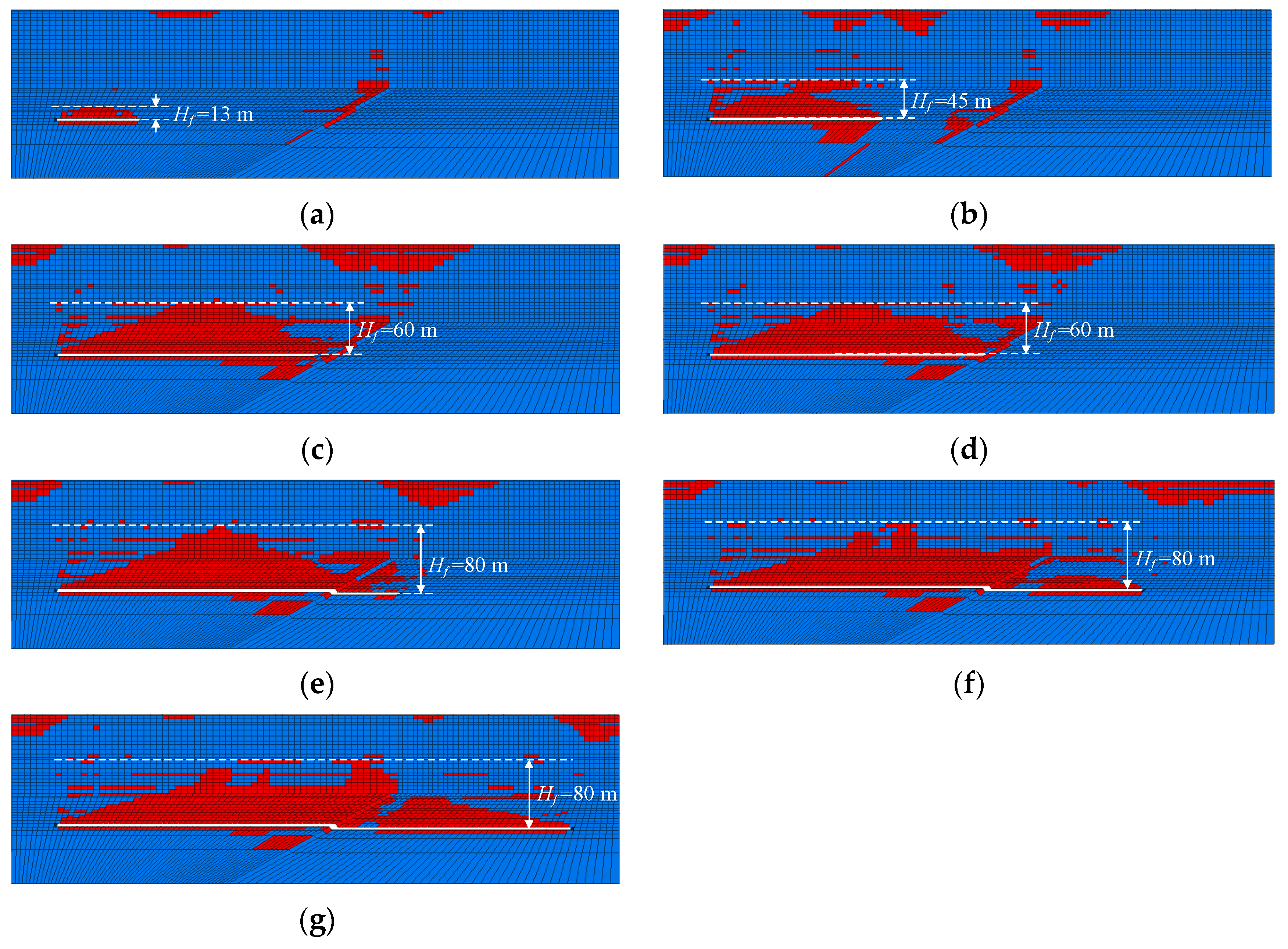
Figure 15 is a sectional view of the plastic zones when the longwall face advanced 100 m, 200 m, 300 m, 320 m, 400 m, 500 m, and 600 m.
The results showed that the plastic and destressed zone distribution in the surrounding rock was
Hf = 13 m when the working face advanced 100 m, a plastic zone appeared near the F6 fault but the overburden failure of working face 15,103 was not affected by the fault (
Figure 15a). Periodic roof weighting in coal mine face appeared and the plastic zone developed to the basic roof with
Hf = 45 m, when the working face advanced 200 m. At this time, the range of the plastic zone near the fault increased (
Figure 15b). With the progress of coal mining, the working face gradually approached the F6 fault. When the working face advanced 300 m (the distance from the F6 fault was 20 m), the plastic zone of the roof was locally connected with the plastic zone near the fault (
Figure 15c,
Hf = 60 m). When the working face advanced 320 m to the fault (
Figure 15d), the plastic zone of the roof was completely connected with the plastic zone near the fault, the height of the plastic zone remained the same (
Hf = 60 m). When the working face advanced 400 m (distance across the F6 fault was 80 m), the height of the FWCZ was increased to 80 m (
Figure 15e).
Figure 15f,g show the simulated vertical cross-sections as the 15,103 working face’s advanced distances were 500 m and 600 m. The distributions of plastic zone in the vertical direction were almost the same, indicating that the plastic zone was fully developed, and the working face reached the super-critical mining stage and the FWCZ was fully developed and stabilized.
It can be considered that overburden caving was fully carried out when the working face crossed F6 reverse fault and reached the supercritical mining stage at 400 m advance, the plastic zone of the roof of hangingwall and footwall of F6 reverse fault was continuous as a whole, which showed that the fracture form of the roof was little affected by the existence of fault plane. Fault and structural fractures were mainly in closed form outside the roof breaking range when the 15,103 working face across F6 reverse fault from hangingwall to the lowerwall, for the mechanical mechanism of reverse fault was a compressive fault. The height of the FWCZ in F6 reverse fault plane was nearly equal to the height of the FWCZ of the two sides in fault.
6. Conclusions
In this paper, the height of the FWCZ in overburden strata of 15,103 working face of Wenzhuang Coal Mine was judged using engineering analogy methods, e.g., the drilling fluid leakage method and drilling television method. Then, a drilling method was adopted to conduct exploration on the terminal location of F6 reverse fault in overburden strata of No. 15 coal seam. Based on this, a numerical simulation analysis method was used to study the failure height of overburden strata after mining of 15,103 working face through F6 reverse fault from the hanging wall to the footwall. The main conclusions are as follows:
(1) The method of drilling fluid leakage method and drilling television method was used to observe the height of the FWCZ of the 15,100 working face, and the height of the FWCZ was determined to be 85.39 m, which provided a reference for the mining overburden failure height of the 15,103 working face.
(2) The results of drilling method showed that F6 reverse fault was not cut through K4 limestone, the disturbance range of F6 reverse fault was located in the FWCZ formed after mining the 15,103 working face.
(3) The results of numerical simulation analysis method showed that the height of the FWCZ was determined to be 80 m. It is indicated that F6 reverse fault had no influence on the height of the FWCZ after mining the 15,103 working face. The thickness of the safety coal pillar of roof after mining was 28.77 m, indicating that there was a very thick overburden strata between the maximal elevation of the fractured zone and the roof goaf water, and mining under old goaf was safe and reliable.
Author Contributions
Data curation, figures preparation and the paper writing, M.Z.; funding acquisition, D.M.; data processing, H.B. and Z.L.; in situ investigation, C.W., Y.L., N.Z. and W.Z.; software, K.W. All authors have read and agreed to the published version of the manuscript.
Funding
This work is supported by Open Fund of State Key Laboratory of Water Resource Protection and Utilization in Coal Mining (Grant No. GJNY-18-73.4) and the National Natural Science Foundation of China (Grant No. 52122404 and 41977238).
Institutional Review Board Statement
Not applicable.
Informed Consent Statement
Not applicable.
Data Availability Statement
The authors confirm that the data supporting the findings of this study are available within the article.
Acknowledgments
We would like to acknowledge the reviewers for their invaluable comments.
Conflicts of Interest
The authors declare no conflict of interest.
References
- Chen, Y.; Tang, L.; Zhu, S. Comprehensive study on identification of water inrush sources from deep mining roadway. Environ. Sci. Pollut. R 2022, 29, 19608–19623. [Google Scholar] [CrossRef]
- Geng, Y.; Wang, S.; Deng, Z.; Wang, B.; Huang, K.; Feng, J.; Miao, Y. Water disaster prevention and control technology in shallow coal seam around the large reservoir in Shenfu coal mine. J. China Coal Soc. 2018, 43, 1999–2006. [Google Scholar]
- Meng, Z.; Shi, X.; Li, G. Deformation, failure and permeability of coal-bearing strata during longwall mining. Eng. Geol. 2016, 208, 69–80. [Google Scholar] [CrossRef]
- Wang, P.; Cheng, J.; Yao, W.; Li, M.; Wang, Y. Technology of detecting water-filled goaf beside borehole using downhole transient electromagnetic method. J. China Coal Soc. 2019, 44, 2502–2508. [Google Scholar]
- Bai, H.; Mao, X.; Wu, Y.; Chen, Z. Research on water-reserved mining with high water pressure under large-scale thrust-fault in ordovician karst. Chin. J. Rock Mech. Eng. 2009, 28, 246–252. [Google Scholar]
- Ma, D.; Duan, H.; Zhang, J.; Liu, X.; Li, Z. Numerical simulation of water–silt inrush hazard of fault rock: A three-phase flow model. Rock Mech. Rock Eng. 2022, 55, 5163–5182. [Google Scholar] [CrossRef]
- Ma, D.; Duan, H.; Zhang, J. Solid grain migration on hydraulic properties of fault rocks in underground mining tunnel: Ra-dial seepage experiments and verification of permeability prediction. Tunn. Undergr. Space Technol. 2022, 126, 104525. [Google Scholar] [CrossRef]
- Huang, Z.; Zeng, W.; Zhao, K. Experimental investigation of the variations in hydraulic properties of a fault zone in western Shandong, China. J. Hydrol. 2019, 574, 822–835. [Google Scholar] [CrossRef]
- Yin, H.; Sang, S.; Xie, D.; Zhao, H.; Li, S.; Li, H.; Zhuang, X. A numerical simulation technique to study fault activation characteristics during mining between fault bundles. Environ. Earth Sci. 2019, 78, 148. [Google Scholar] [CrossRef]
- Huang, B.; Liu, C.; Xu, J. Effect of little fault in working face on water conducted fissure height. J. China Coal Soc. 2009, 34, 1316–1321. [Google Scholar]
- Huang, B.; Liu, F.; Wang, Y.; Wang, X.; Ji, W. Development of water conductive fissures in hidden reversed fault in thin-ning-out overlying strata of a stope. J. Min. Saf. Eng. 2010, 27, 377–381. [Google Scholar]
- Wu, L.; Bai, H.; Yuan, C.; Wu, G.; Xu, C.; Du, Y. A water-rock coupled model for fault water inrush: A case study in Xiaochang coal mine, China. Adv. Civ. Eng. 2019, 2019, 9343917. [Google Scholar] [CrossRef]
- Hu, Y.; Sun, J.; Liu, W.; Wei, D. The evolution and prevention of water inrush due to fault activation at working face No. II 632 in the Hengyuan coal mine. Mine Water Environ. 2019, 38, 93–103. [Google Scholar] [CrossRef]
- Wang, X.; Zhu, S.; Yu, H.; Liu, Y. Comprehensive analysis control effect of faults on the height of fractured water-conducting zone in longwall mining. Nat. Hazards 2021, 108, 2143–2165. [Google Scholar] [CrossRef]
- Yu, Q.; Zhang, H.; Zhang, Y.; Deng, W.; Zhang, G. Analysis of fault activation mechanism and influencing factors caused by mining. J. China Coal Soc. 2019, 44 (Suppl. S1), 18–30. [Google Scholar]
- Ma, D.; Kong, S.; Li, Z.; Zhang, Q.; Wang, Z.; Zhou, Z. Effect of wetting-drying cycle on hydraulic and mechanical properties of cemented paste backfill of the recycled solid wastes. Chemosphere 2021, 282, 131163. [Google Scholar] [CrossRef]
- Wang, J.; Ma, D.; Li, Z.; Huang, Y.; Du, F. Experimental investigation of damage evolution and failure criterion on hollow cylindrical rock samples with different bore diameters. Eng. Fract. Mech. 2022, 260, 108182. [Google Scholar] [CrossRef]
- Zheng, Z.; Liu, R.; Zhang, Q. Numerical simulation and risk assessment of water inrush in a fault zone that contains a soft infill. Mine Water Environ. 2019, 38, 667–675. [Google Scholar] [CrossRef]
- Cui, F.; Wu, Q.; Lin, Y.; Zeng, Y.; Zhang, K. Damage features and formation mechanism of the strong water inrush disaster at the Daxing co mine, Guangdong province, China. Mine Water Environ. 2018, 37, 346–350. [Google Scholar] [CrossRef]
- Ma, D.; Duan, H.; Zhang, J.; Bai, H. A state-of-the-art review on rock seepage mechanism of water inrush disaster in coal mines. Int. J. Coal Sci. Technol. 2022, 9, 50. [Google Scholar] [CrossRef]
- Guo, W.; Yang, W.; Ma, Z.; Wen, P.; Liu, X.; Bai, E. Stability criterion of overburden structure above goaf under building load and its application. J. China Coal Soc. 2022, 47, 2207–2217. [Google Scholar]
- Jiang, C.; Gao, X.; Hou, B.; Zhang, S.; Zhang, J.; Li, C.; Wang, W. Occurrence and environmental impact of coal mine goaf water in karst areas in China. J. Clean. Prod. 2020, 275, 123813. [Google Scholar] [CrossRef]
- Ma, D.; Li, Q.; Cai, K.; Zhang, J.; Li, Z.; Hou, W.; Sun, Q.; Li, M.; Du, F. Understanding water inrush hazard of weak geological structure in deep mine engineering: A seepage-induced erosion model considering tortuosity. J. Cent. South Univ. 2023, 30, 517–529. [Google Scholar] [CrossRef]
- Li, C.; Xu, Z. Numerical modeling and investigation of fault-induced water inrush hazard under different mining advancing directions. Mathematics 2022, 10, 1561. [Google Scholar] [CrossRef]
- Khayrutdinov, M.M.; Golik, V.I.; Aleksakhin, A.V.; Trushina, E.V.; Lazareva, N.V.; Aleksakhina, Y.V. Proposal of an Algorithm for Choice of a Development System for Operational and Environmental Safety in Mining. Resources 2022, 11, 88. [Google Scholar] [CrossRef]
- Rybak, J.; Tyulyaeva, Y.; Kongar-Syuryun, C.; Khayrutdinov, A.M.; Akinshin, I. Mining Science. Geomech. Subst. Parameters Technol. Min. Salt Depos. A Backfill 2021, 28, 19–32. [Google Scholar]
- Kongar-Syuryun, C.; Ubysz, A.; Faradzhov, V. Models and algorithms of choice of development technology of deposits when selecting the composition of the backfilling mixture. Earth Environ. Sci. 2021, 684, 012008. [Google Scholar] [CrossRef]
- Adigamov, A.E.; Yudenkov, A.V. Stress-strain behavior model of disturbed rock mass with regard to anisotropy and discontinuities. Min. Inf. Anal. Bull. 2021, 8, 93–103. [Google Scholar] [CrossRef]
- Zhang, X.; Wang, H.; Shen, S. Effect of small faults activation on failure and permeability of overburden strata in goaf. Coal Sci. Technol. 2022, 50, 75–85. [Google Scholar]
- Tan, Y.; Cheng, H.; Lv, W.; Yan, W.; Guo, W.; Zhang, Y.; Qi, T.; Yin, D.; Wei, S.; Ren, J.; et al. Calculation of the height of the water-conducting fracture zone based on the analysis of critical fracturing of overlying strata. Sustainability 2022, 14, 5221. [Google Scholar] [CrossRef]
- Ma, D.; Zhang, J.; Duan, H.; Huang, Y.; Li, M.; Sun, Q.; Zhou, N. Reutilization of gangue wastes in underground backfilling mining: Overburden aquifer protection. Chemosphere 2021, 264, 128400. [Google Scholar] [CrossRef]
- Xie, X.; Hou, E.; Wang, S.; Sun, X.; Hou, P.; Wang, S.; Xie, Y.; Huang, Y. Formation mechanism and the height of the water-conducting fractured zone induced by middle deep coal seam mining in a sandy region: A case study from the Xiaobaodang coal mine. Adv. Civ. Eng. 2021, 2021, 6684202. [Google Scholar] [CrossRef]
- Zhai, M.; Bai, H.; Wu, L.; Wu, G.; Yan, X.; Ma, D. A reinforcement method of floor grouting in high-water pressure working face of coal mines: A case study in Luxi coal mine, North China. Environ. Earth Sci. 2022, 81, 28. [Google Scholar] [CrossRef]
- Cao, Z.; Ju, J.; Xu, J. Distribution model of water-conducted fracture main channel and its flow characteristics. J. China Coal Soc. 2019, 44, 3719–3728. [Google Scholar]
- Guo, W.; Lou, G.; Zhao, B. Study on the height of water-conductive fracture zone in alternate overburden of soft and hard with top coal caving mining in Lugou coal mine. J. Min. Saf. Eng. 2019, 36, 519–526. [Google Scholar]
- Guo, W.; Zhao, G.; Lou, G.; Wang, S. A new method of predicting the height of the fractured water-conducting zone due to high-intensity longwall coal mining in China. Rock Mech. Rock Eng. 2019, 52, 2789–2802. [Google Scholar] [CrossRef]
- Li, Q.; Ju, J.; Cao, Z.; Gao, F.; Li, J. Suitability evolution of underground reservoir technology based on the discriminant of the height of water conduction fracture zone. J. China Coal Soc. 2017, 42, 2116–2124. [Google Scholar]
- Tan, Y.; Guo, W.; Yang, D. Analysis on height of “two zones” under subcritical mining in shallow coal seam with hard roof. J. Min. Saf. Eng. 2017, 34, 845–851. [Google Scholar]
- He, C.; Xiao, F.; Zhang, Z.; Ding, D. Prediction of the height of the transmissive fractured belt of a mining stope under aquifer in Kangjiawan mine. J. Min. Saf. Eng. 2011, 28, 122–126. [Google Scholar]
- Lai, X.; Zhang, X.; Shan, P.; Cui, F.; Liu, B.; Bai, R. Study on development law of water-conducting fractures in overlying strata of three soft coal seam mining under thick loose layers. Chin. J. Rock Mech. Eng. 2021, 40, 1739–1750. [Google Scholar]
- Yang, D.; Guo, W.; Zhao, G.; Tan, Y.; Yang, W. Height of water-conducting zone in longwall top-coal caving mining under thick alluvium and soft overburden. J. China Coal Soc. 2019, 44, 3308–3316. [Google Scholar]
| Disclaimer/Publisher’s Note: The statements, opinions and data contained in all publications are solely those of the individual author(s) and contributor(s) and not of MDPI and/or the editor(s). MDPI and/or the editor(s) disclaim responsibility for any injury to people or property resulting from any ideas, methods, instructions or products referred to in the content. |
© 2023 by the authors. Licensee MDPI, Basel, Switzerland. This article is an open access article distributed under the terms and conditions of the Creative Commons Attribution (CC BY) license (https://creativecommons.org/licenses/by/4.0/).


