Experimental Study of Mesostructure Deformation Characteristics of Unsaturated Tailings with Different Moisture Content


Abstract
:
1. Introduction
2. Test Materials, Equipment, and Method
2.1. Test Materials
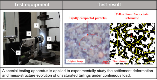
2.2. Test Equipment
2.3. Test Scheme
2.4. Test Steps
3. Results and Analysis
3.1. Displacement Deformation Characteristics
3.2. Particles Mesostructure Characteristics
4. Discussion
5. Conclusions
Author Contributions
Funding
Institutional Review Board Statement
Informed Consent Statement
Data Availability Statement
Acknowledgments
Conflicts of Interest
References
- Kossoff, D.; Dubbin, W.E.; Alfredsson, M.; Edwards, S.J.; Macklin, M.G.; Hudson-Edwards, K.A. Mine Tailings Dams: Characteristics, Failure, Environmental Impacts, and Remediation. Appl. Geochem. 2014, 51, 229–245. [Google Scholar] [CrossRef] [Green Version]
- Vick, S.G. Planning, Design, and Analysis of Tailings Dams; BiTech Publishers: Vancouver, BC, Canada, 1990. [Google Scholar]
- Rico, M.; Benito, G.; Diez-Herrero, A. Floods from Tailings Dam Failures. J. Hazard Mater. 2008, 154, 79–87. [Google Scholar] [CrossRef] [PubMed] [Green Version]
- Santamarina, J.C.; Torres-Cruz, L.A.; Bachus, R.C. Why Coal Ash and Tailings Dam Disasters Occur: Knowledge Gaps and Management Shortcomings Contribute to Catastrophic Dam Failures. Science 2019, 364, 526–528. [Google Scholar] [CrossRef]
- Van Niekerk, H.J.; Viljoen, M.J. Causes and Consequences of the Merriespruit and Other Tailings-Dam Failures. Land Degrad. Dev. 2005, 16, 201–212. [Google Scholar] [CrossRef]
- Glotov, V.E.; Chlachula, J.; Glotova, L.P.; Little, E. Causes and Environmental Impact of the Gold-Tailings Dam Failure at Karamken, the Russian Far East. Eng. Geol. 2018, 245, 236–247. [Google Scholar] [CrossRef]
- Silva Rotta, L.H.; Alcântara, E.; Park, E.; Negri, R.G.; Lin, Y.N.; Bernardo, N.; Mendes, T.S.G.; Souza Filho, C.R. The 2019 Brumadinho Tailings Dam Collapse: Possible Cause and Impacts of the Worst Human and Environmental Disaster in Brazil. Int. J. Appl. Earth Obs. 2020, 90, 102119. [Google Scholar] [CrossRef]
- Du, Z.; Ge, L.; Ng, A.H.; Zhu, Q.; Horgan, F.G.; Zhang, Q. Risk Assessment for Tailings Dams in Brumadinho of Brazil Using Insar Time Series Approach. Sci. Total Environ. 2020, 717, 137125. [Google Scholar] [CrossRef]
- Thompson, F.; de Oliveira, B.C.; Cordeiro, M.C.; Masi, B.P.; Rangel, T.P.; Paz, P.; Freitas, T.; Lopes, G.; Silva, B.S.; Cabral, A.S.; et al. Severe Impacts of the Brumadinho Dam Failure (Minas Gerais, Brazil) on the Water Quality of the Paraopeba River. Sci. Total Environ. 2020, 705, 135914. [Google Scholar] [CrossRef]
- Armstrong, M.; Petter, R.; Petter, C. Why Have so Many Tailings Dams Failed in Recent Years? Resour. Policy 2019, 63, 101412. [Google Scholar] [CrossRef]
- Wei, Z.A.; Yin, G.Z.; Wang, J.G.; Wan, L.; Li, G.Z. Design, Construction and Management of Tailings Storage Facilities for Surface Disposal in China: Case Studies of Failures. Waste Manag. Res. 2013, 31, 106–112. [Google Scholar] [CrossRef]
- Fredlund, D.G.; Rahardjo, H.; Fredlund, M.D. Unsaturated Soil Mechanics in Engineering Practice; John Wiley & Sons: Hoboken, NJ, US, 2012. [Google Scholar]
- Zandarin, M.T.; Decop, L.A.; Rodriguez, R.; Zabala, F. The Role of Capillary Water in the Stability of Tailing Dams. Eng. Geol. 2009, 105, 108–118. [Google Scholar] [CrossRef]
- Cao, G.S.; Wang, W.S.; Yin, G.Z.; Wei, Z.A. Experimental Study of Shear Wave Velocity in Unsaturated Tailings Soil with Variant Grain Size Distribution. Constr. Build. Mater. 2019, 228, 116744. [Google Scholar] [CrossRef]
- Ishihara, K.; Ueno, K.; Yamada, S.; Yasuda, S.; Yoneoka, T. Breach of a Tailings Dam in the 2011 Earthquake in Japan. Soil Dyn. Earthq. Eng. 2015, 68, 3–22. [Google Scholar] [CrossRef]
- Pak, A.; Nabipour, M. Numerical Study of the Effects of Drainage Systems on Saturated/Unsaturated Seepage and Stability of Tailings Dams. Mine Water Environ. 2017, 36, 341–355. [Google Scholar] [CrossRef]
- Rico, M.; Benito, G.; Salgueiro, A.R.; Diez-Herrero, A.; Pereira, H.G. Reported Tailings Dam Failures. A Review of the European Incidents in the Worldwide Context. J. Hazard Mater. 2008, 152, 846–852. [Google Scholar] [CrossRef] [Green Version]
- Agurto-Detzel, H.; Bianchi, M.; Assumpcao, M.; Schimmel, M.; Collaco, B.; Ciardelli, C.; Barbosa, J.R.; Calhau, J. The Tailings Dam Failure of 5 November 2015 in se Brazil and Its Preceding Seismic Sequence. Geophys. Res. Lett. 2016, 43, 4929–4936. [Google Scholar] [CrossRef] [Green Version]
- Robertson, P.K.; Melo, L.; Williams, D.J.; Wilson, G.W. Report of the Expert Panel on the Technical Causes of the Failure of Feijão Dam I; 2019. Available online: https://bdrb1investigationstacc.z15.web.core.windows.net/ (accessed on 20 November 2020).
- Narvaez, B.; Aubertin, M.; Saleh-Mbemba, F. Determination of the Tensile Strength of Unsaturated Tailings Using Bending Tests. Can. Geotech. J. 2015, 52, 1874–1885. [Google Scholar] [CrossRef]
- Robertson, P.K.; da Fonseca, A.V.; Ulrich, B.; Coffin, J. Characterization of Unsaturated Mine Waste: A Case History. Can. Geotech. J. 2017, 54, 1752–1761. [Google Scholar] [CrossRef] [Green Version]
- Zhang, C.; Liu, H.; Yang, C.; Wu, S. Mechanical Characteristics of Non-Saturated Tailings and Dam Stability. Int. J. Min. Reclam. Environ. 2017, 31, 530–543. [Google Scholar] [CrossRef]
- Zhang, F.; Wilson, G.W.; Fredlund, D.G. Estimation of Permeability Function for Bulyanhulu Tailings. Geotech. Test. J. 2019, 42, 670–686. [Google Scholar] [CrossRef]
- Schafer, H.; Beier, N. Estimating Soil-Water Characteristic Curve from Soil-Freezing Characteristic Curve for Mine Waste Tailings Using Time Domain Reflectometry. Can. Geotech. J. 2020, 57, 73–84. [Google Scholar] [CrossRef]
- Fisseha, B.; Bryan, R.; Simms, P. Evaporation, Unsaturated Flow, and Salt Accumulation in Multilayer Deposits of “Paste” Gold Tailings. J. Geotech. Geoenviron. 2010, 136, 1703–1712. [Google Scholar] [CrossRef]
- Li, X.; Li, X.S. Micro-Macro Quantification of the Internal Structure of Granular Materials. J. Eng. Mech. 2009, 135, 641–656. [Google Scholar] [CrossRef]
- Su, H.Z.; Fu, Z.Q.; Gao, A.; Wen, Z.P. Particle Flow Code Method-Based Meso-Scale Identification for Seepage Failure of Soil Levee. Transp. Porous Med. 2017, 119, 311–336. [Google Scholar] [CrossRef]
- Wang, Y.; Li, X.; Zhang, B.; Wu, Y.F. Meso-Damage Cracking Characteristics Analysis for Rock and Soil Aggregate with ct Test. Sci. China Technol. Sci. 2014, 57, 1361–1371. [Google Scholar] [CrossRef]
- Liu, Y.N.; Liu, E.N.; Yin, Z.Y. Constitutive Model for Tailing Soils Subjected to Freeze-Thaw Cycles Based on Meso-Mechanics and Homogenization Theory. Acta Geotech. 2020, 15, 2433–2450. [Google Scholar] [CrossRef]
- Wang, Y.; Li, C.H.; Hu, Y.Z. Use of X-ray Computed Tomography to Investigate the Effect of Rock Blocks on Meso-Structural Changes in Soil-Rock Mixture under Triaxial Deformation. Constr. Build. Mater. 2018, 164, 386–399. [Google Scholar] [CrossRef]
- Xu, W.J.; Hu, L.M.; Gao, W. Random Generation of the Meso-Structure of a Soil-Rock Mixture and Its Application in the Study of the Mechanical Behavior in a Landslide Dam. Int. J. Min. Sci. Technol. 2016, 86, 166–178. [Google Scholar] [CrossRef]
- Zhu, H.X.; Nicot, F.; Darve, F. Meso-Structure Evolution in a 2d Granular Material During Biaxial Loading. Granul. Matter 2016, 18, 3. [Google Scholar] [CrossRef]
- Nguyen, N.S.; Magoariec, H.; Cambou, B.; Danescu, A. Analysis of Structure and Strain at the Meso-Scale in 2d Granular Materials. Int. J. Solids Struct. 2009, 46, 3257–3271. [Google Scholar] [CrossRef] [Green Version]
- Chang, N.; Heymann, G.; Clayton, C. The Effect of Fabric on the Behaviour of Gold Tailings. Geotechnique 2011, 61, 187–197. [Google Scholar] [CrossRef] [Green Version]
- Shi, Y.; Li, C.; Long, D. Study of the Microstructure Characteristics of Three Different Fine-Grained Tailings Sand Samples during Penetration. Materials 2020, 13, 1585. [Google Scholar] [CrossRef] [Green Version]
- Zhang, Q.G.; Yin, G.Z.; Fan, X.Y.; Wei, Z.A.; Wang, W.S.; Nie, W. Loading Capacity and Deformation Characteristics of Tailings Based on a Fractal Geometrical Analysis of the Particle Microstructure. Minerals 2015, 5, 86–103. [Google Scholar] [CrossRef] [Green Version]
- Zhang, Q.G.; Yin, G.Z.; Wei, Z.A.; Fan, X.Y.; Wang, W.S.; Nie, W. An Experimental Study of the Mechanical Features of Layered Structures in Dam Tailings from Macroscopic and Microscopic Points of View. Eng. Geol. 2015, 195, 142–154. [Google Scholar] [CrossRef]
- Chen, Q.; Zhang, C.; Yang, C.; Ma, C.; Pan, Z. Effect of Fine-Grained Dipping Interlayers on Mechanical Behavior of Tailings Using Discrete Element Method. Eng. Anal. Bound. Elements 2019, 104, 288–299. [Google Scholar] [CrossRef]
- Yang, Y.H.; Wei, Z.A.; Fourie, A.; Chen, Y.L.; Zheng, B.B.; Wang, W.S.; Zhuang, S.N. Particle Shape Analysis of Tailings Using Digital Image Processing. Environ. Sci. Pollut. Res. 2019, 26, 26397–26403. [Google Scholar] [CrossRef]
- Sun, Q.C.; Wang, G.Q. An Introduction to Granular Material Mechanics; Science Press: Beijing, China, 2009. [Google Scholar]
- Ministry of Housing and Urban-Rural Development of the People’s Republic of China. Code for Design of Tailings Facilities; China Planning Press: Beijing, China, 2013; Volume GB50863-2013. [Google Scholar]
- American Society of Testing Materials. Standard Practice for Classification of Soils for Engineering Purposes (Unified Soil Classification System); ASTM International: West Conshohocken, PA, US, 2017; Volume ASTM Standard D2487-17. [Google Scholar]
- Pica Ciamarra, M.; Lippiello, E.; Godano, C.; de Arcangelis, L. Unjamming Dynamics: The Micromechanics of a Seismic Fault Model. Phys. Rev. Lett. 2010, 104, 238001. [Google Scholar] [CrossRef] [Green Version]
- Wiacek, J. Geometrical Parameters of Binary Granular Mixtures with Size Ratio and Volume Fraction: Experiments and Dem simulations. Granul. Matter 2016, 18, 42. [Google Scholar] [CrossRef] [Green Version]
- Zhou, W.; Wu, W.; Ma, G.; Ng, T.T.; Chang, X.L. Undrained Behavior of Binary Granular Mixtures with Different Fines Contents. Powder Technol. 2018, 340, 139–153. [Google Scholar] [CrossRef]
- Lappalainen, K.; Manninen, M.; Alopaeus, V.; Aittamaa, J.; Dodds, J. An Analytical Model for Capillary Pressure–Saturation Relation for Gas–Liquid System in a Packed-Bed of Spherical Particles. Transp. Porous Med. 2008, 77, 17–40. [Google Scholar] [CrossRef]
- Lu, N.; Kim, T.H.; Sture, S.; Likos, W.J. Tensile Strength of Unsaturated Sand. J. Eng. Mech. 2009, 135, 1410–1419. [Google Scholar] [CrossRef] [Green Version]
- Kim, T.H.; Sture, S. Capillary-Induced Tensile Strength in Unsaturated Sands. Can. Geotech. J. 2008, 45, 726–737. [Google Scholar] [CrossRef]
- Wang, J.P.; Li, X.; Yu, H.S. Stress-Force-Fabric Relationship for Unsaturated Granular Materials in Pendular States. J. Eng. Mech. 2017, 143, 04017068. [Google Scholar] [CrossRef] [Green Version]
- Wang, J.P.; Gallo, E.; François, B.; Gabrieli, F.; Lambert, P. Capillary Force and Rupture of Funicular Liquid Bridges between Three Spherical Bodies. Powder Technol. 2017, 305, 89–98. [Google Scholar] [CrossRef]
- Grof, Z.; Lawrence, C.J.; Stepanek, F. Computer Simulation of Evolving Capillary Bridges in Granular Media. Granul. Matter 2007, 10, 93–103. [Google Scholar] [CrossRef]
- Grof, Z.; Lawrence, C.J.; Stepanek, F. The Strength of Liquid Bridges in Random Granular Materials. J. Colloid Interface Sci. 2008, 319, 182–192. [Google Scholar] [CrossRef]
- Lu, N.; Godt, J.W.; Wu, D.T. A Closed-Form Equation for Effective Stress in Unsaturated Soil. Water Resour. Res. 2010, 46, W05515. [Google Scholar] [CrossRef]


| Specific Gravity | Liquid Limit (%) | Plastic Limit (%) | Plastic Index | Gravel (%) | Sand (%) | Silt (%) | Clay (%) | D50 (mm) | Cu | Cc |
|---|---|---|---|---|---|---|---|---|---|---|
| 2.07 | 16.97 | 10.67 | 6.30 | 0 | 39.52 | 46.04 | 14.44 | 0.032 | 26.03 | 0.84 |
Publisher’s Note: MDPI stays neutral with regard to jurisdictional claims in published maps and institutional affiliations. |
© 2020 by the authors. Licensee MDPI, Basel, Switzerland. This article is an open access article distributed under the terms and conditions of the Creative Commons Attribution (CC BY) license (http://creativecommons.org/licenses/by/4.0/).
Share and Cite
Geng, W.; Wang, W.; Wei, Z.; Huang, G.; Jing, X.; Jiang, C.; Tian, S. Experimental Study of Mesostructure Deformation Characteristics of Unsaturated Tailings with Different Moisture Content. Water 2021, 13, 15. https://doi.org/10.3390/w13010015
Geng W, Wang W, Wei Z, Huang G, Jing X, Jiang C, Tian S. Experimental Study of Mesostructure Deformation Characteristics of Unsaturated Tailings with Different Moisture Content. Water. 2021; 13(1):15. https://doi.org/10.3390/w13010015
Chicago/Turabian StyleGeng, Weile, Wensong Wang, Zuoan Wei, Gun Huang, Xiaofei Jing, Changbao Jiang, and Sen Tian. 2021. "Experimental Study of Mesostructure Deformation Characteristics of Unsaturated Tailings with Different Moisture Content" Water 13, no. 1: 15. https://doi.org/10.3390/w13010015