Article

Mobile Robot System for Selective Asparagus Harvesting

Faculty of Electrical Engineering, University of Ljubljana, Tržaška Cesta 25, 1000 Ljubljana, Slovenia
*
Author to whom correspondence should be addressed.
Agronomy 2023, 13(7), 1766; https://doi.org/10.3390/agronomy13071766
Submission received: 8 June 2023 / Revised: 28 June 2023 / Accepted: 28 June 2023 / Published: 29 June 2023
(This article belongs to the Special Issue Agricultural Automation and Innovative Agricultural Systems)

Abstract

:
Asparagus harvesting presents unique challenges, due to the variability in spear growth, which makes large-scale automated harvesting difficult. This paper describes the development of an asparagus harvesting robot system. The system consists of a delta robot mounted on a mobile track-based platform. It employs a real-time asparagus detection algorithm and a sensory system to determine optimal harvesting points. Low-level control and high-level control are separated in the robot control. The performance of the system was evaluated in a laboratory field mock-up and in the open field, using asparagus spears of various shapes. The results demonstrate that the system detected and harvested 88% of the ready-to-harvest spears, with an average harvesting cycle cost of 3.44 s ± 0.14 s . In addition, outdoor testing in an open field demonstrated a 77% success rate in identifying and harvesting asparagus spears.

1. Introduction

Agriculture, one of the oldest and most essential industries, has undergone a significant transformation as a result of the introduction of innovative technologies. Robotics is a technology that has the potential to revolutionize the agronomy industry [1,2,3]. Both Lytridis et al. [4] and Bergerman et al. [5] suggest that the incorporation of robotics into agriculture could address a number of issues, including labor scarcity, rising production costs, and environmental sustainability; in addition, it could improve precision, efficiency, and productivity, resulting in increased yields and profitability [3,4,6]. The current state of the art in agricultural robotics includes crop monitoring [7], weed control [8,9], harvesting [10,11], and post-harvesting [12]. Robots are utilized for a variety of agricultural tasks, including soil monitoring [13], seeding [14], seedling manipulation [15], fertilization [16], irrigation [17], and crop protection [18,19]. These technologies enable efficient and accurate crop monitoring, allowing for timely interventions to promote optimal growth.
Despite its economic significance, asparagus presents unique harvesting challenges. Asparagus spears are delicate, and their growth is variable, making large-scale automated harvesting challenging [20]. In recent years, significant progress has been made in the development of robot systems for asparagus harvesting, with the goal of increasing efficiency and decreasing labor costs. The University of Waikato and Robotics Plus Limited have developed a robotic asparagus harvester that is pulled by a tractor [21]. A highly effective convolutional neural network (CNN) has been developed, to detect asparagus spears [22]. Irie et al. [23] presented an asparagus harvesting robot that used an electrical cart equipped with a 3D camera and robotic arm to harvest spears along the furrow: the time needed to harvest a single asparagus spear was reduced to 13.7 s. Irie and Taguchi [24], in a later study, upgraded the sensory system, to include a laser scanner, reducing the harvesting time to approximately 7.5 s per spear. Funami et al. [25] created an electro-pneumatic, four-degrees-of-freedom robotic system capable of harvesting asparagus spears from ridges, even in dense vegetation. The asparagus harvesting trolley, designed by Zhang et al. [26], utilizes a pneumatic punching and cutting mechanism, and two pinch rollers, to grab and move cut spears onto a conveyor belt.
Inaho Inc., Kamakura, Japan (https://en.inaho.co/, accessed on 8 June 2023), introduced a tracked robotic system with a robotic arm and an infrared detection device for spear detection for greenhouse asparagus harvesting [27]. Several funded initiatives have sought to develop comprehensive harvesting solutions for asparagus: the AmLight project aimed to create an automatic harvesting system for green asparagus with stalk detection in ambient light; the MANTIS project sought to develop an automated asparagus harvester; GARotics (http://echord.eu/garotics/, accessed on 8 June 2023) presented a mobile platform on wheels, equipped with an RGBD camera for spear detection, and two Cartesian manipulators capable of harvesting five spears per meter [28].
To ensure accurate and selective harvesting, numerous asparagus detection methods have been investigated. The University of Waikato compared the performance of faster, region-based convolutional neural networks (FRCNN) to that of a single shot multibox detector (SSD), and concluded that FRCNN-based detectors are better suited to asparagus detection [29]. Kennedy et al. [30] presented a single-view representation of information from a multi-camera system, combined with temporal filtering, to reliably locate asparagus spears in laboratory and outdoor settings in real time. Sakai et al. [31] used two laser scanners for vertical scanning, to detect asparagus spears, with an accuracy of approximately 75% and a harvesting time of more than 10 s per spear. Leu et al. [28] utilized RGB and depth images to generate a point cloud for the classification, recognition, and tracking of asparagus. Hong et al. [32] utilized an improved YOLOv5 algorithm for asparagus recognition and detection in complex environments, achieving an average mean precision of nearly 99% percent. Lastly, Liu et al. [33] introduced depth-aided mask RCNN for asparagus detection, demonstrating a better balance between precision and speed than existing algorithms.
The development of a novel harvesting robot was motivated by the need to address manual labor shortages. Existing options are limited to large machines, and some are only appropriate for confined environments, such as greenhouses. Moreover, current software solutions are computationally intensive, require extensive training databases, and are unsuitable for deployment on low-cost hardware. The development of a lightweight robot intended to replace a single large machine with multiple smaller ones, thereby increasing overall efficiency, was our primary objective, the design of which should be adaptable to a variety of tasks, while the robotic system should include a robust and computationally efficient spear detection algorithm. By providing a cost-effective solution, we hope to make asparagus production accessible to a greater number of growers.
This paper presents a novel design for a lightweight agricultural robot intended for the efficient harvesting of stem vegetables, with a focus on green asparagus. In Section 2, we describe the mechanical design and software control system of the robot, and the implementation of a point-cloud-segmentation-based asparagus detection algorithm. Section 3 provides a comprehensive evaluation of the performance of the robotic system in controlled laboratory settings and in actual asparagus fields. Section 4 analyzes the test results, and provides recommendations for future work.

2. Materials and Methods

To optimize asparagus harvesting, a mobile platform with precise and quick mechanisms was required. To aid in this endeavor, a real-time asparagus detection algorithm was used, to determine the optimal harvesting points. This algorithm was designed to be lightweight, to promote efficient harvesting.

2.1. Hardware Design

The harvesting robot system comprised a delta robot mounted on a mobile platform with tracks. The gripper on the delta robot was customized for grasping and cutting asparagus spears. The platform was also equipped with a sensory system for detecting asparagus spears.

2.1.1. Delta Robot

We developed a fast and dependable robotic mechanism for harvesting asparagus spears in an efficient manner. Our solution employed a delta parallel robot with three identical arms that were triple symmetric, which provided superior dynamics and velocity compared to serial mechanisms. Each arm consisted of an actuated rotary joint and two universal joints, and was powered by a Beckhoff AM8113 servo motor and a WPLE040 gear reducer with a 1:10 gear ratio. The arms were connected to a common platform with three degrees of freedom, enabling precise control over the position of the robot’s tool center point (TCP). Figure 1 demonstrates the robot’s CAD model.
The three arms were evenly spaced at a radius of 0.15 m around a central point. The first segment was 0.25 m in length, and the second segment was 0.50 m in length. The diameter of the TCP platform was 0.13 m . The robot’s workspace had the shape of a bowl, with [ 0.58 , 0.56 ] m values in the x direction, [ 0.50 , 0.50 ] m values in the y direction, and [ 0.75 , 0 ] m values in the z direction. In the center, the maximum height value was 0.24 m . The robot’s workspace encompassed a cuboid with overall dimensions of 0.7 m × 0.7 m × 0.36 m .
A fourth degree of rotational freedom was added to the mechanism, in order to ensure that the gripper approached the asparagus in the proper manner. This additional rotation enabled the proper orientation of the tool to be set. A DC motor, in combination with timing belt transmission, was used for actuation, to ensure the tool’s correct orientation. As asparagus spears grow randomly, this upgrade was essential for approaching each spear successfully.
For a reliable grasp on asparagus spears of all sizes and shapes, we developed a specialized gripper. The gripper consisted of three parts: a rigid finger made of hard plastic; a rubber finger in the shape of a fin; and a narrow blade for cutting the spear. We utilized the blade from a utility knife, because it was sturdy, long-lasting, readily accessible, and simple to replace. Figure 2 displays a detailed CAD model of the gripper.
Using an axis-in-axis design, we added a second DC motor to the robot’s upper plate, so that the gripper could rotate and be actuated. This design guaranteed that the gripper could effectively grasp and cut the asparagus spears, providing a comprehensive harvesting solution.

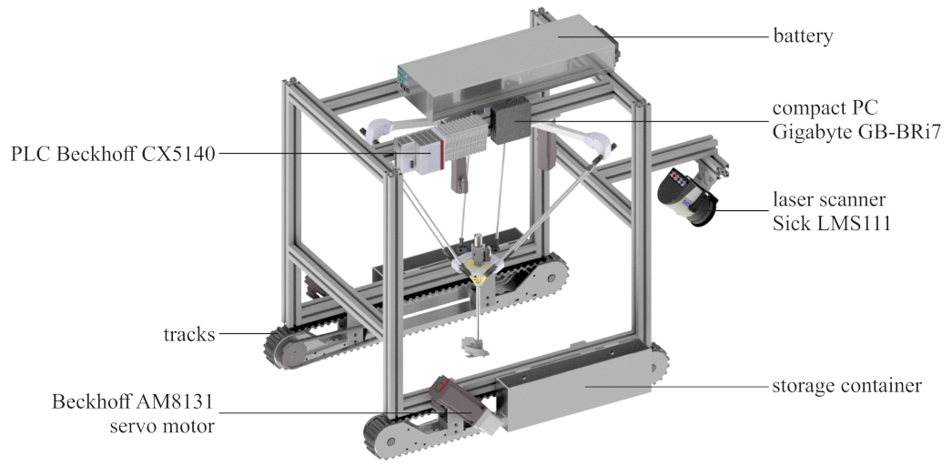
2.1.2. Mobile Platform

The delta robot was mounted on a mobile platform with two rubber tracks that provided traction for field driving. The distance between the tracks was 600 mm, providing sufficient space for traversing asparagus fields. The outer dimensions of the mobile platform, excluding the sensor, were 1 m × 0.66 m × 1.06 m (length × width × height). The sensor bar added 0.35 m to the overall length when it was included. The tracks were propelled by a Beckhoff AM8131 (Beckhoff Automation GmbH & Co. KG, Verl, Germany) synchronous motor with a combination of angular and chain reduction resulting in a total ratio of 70:1. This configuration permitted the platform to attain a nominal speed of 0.2 m/s.
The mobile platform was made of extruded aluminum, which allowed the delta robot to be affixed at a height of 0.9 m. The platform also contained a battery, a low-level programmable logic controller Beckhoff CX5140 (Beckhoff Automation GmbH & Co. KG, Verl, Germany), and a high-level controller based on an ultra-compact PC Gigabyte GB-BRi7-10710 (Giga-Byte Technologies CO., LTD, New Taipei City, Taiwan) that was affixed above the delta robot. A Sick LMS111 (SICK AG, Waldkirch, Germany) laser scanner was installed at the front of the platform, oriented in the direction opposite the motion, in order to detect the asparagus. Figure 3 displays the CAD model of the platform, with its components labeled.

2.2. Control

The control of the asparagus harvesting robot was divided into two parts (see Figure 4): (a) low-level control, for controlling the individual motors, and for calculating the forward/inverse kinematics of both the delta robot and the mobile platform; (b) high-level control, for asparagus spear detection and localization, as well as path planning for the delta robot.

2.2.1. Low-Level Control

We implemented low-level control on the Beckhoff CX5140 (Beckhoff Automation GmbH & Co. KG, Verl, Germany) programmable logic controller, using three Beckhoff EL7211 servo motor controllers to control the delta robot’s motors, two Beckhoff EL7201 (Beckhoff Automation GmbH & Co. KG, Verl, Germany) servo motor controllers to control the track motors, and the Beckhoff EL7342 (Beckhoff Automation GmbH & Co. KG, Verl, Germany) 2-channel motion interface for the DC motors. The motor controllers were configured to accept velocity as the reference input, in order to facilitate motor control. The frequency of the control loop was 1 kHz.
  • Communication
We used the automation device specification (ADS) protocol, a transport layer developed for data exchange between software modules within the TwinCAT system, to communicate with the high-level control. To facilitate ADS communication, two bidirectional data blocks were created: one for the mobile platform, and one for the delta robot. The frequency of the data exchange between the Beckhoff controller and the high-level controller was 1 kHz.
  • Mobile platform kinematics
A simple mathematical model was used to describe the kinematics of the mobile platform’s low-level control [34]. Under idealized conditions, ignoring factors such as wheel slip and friction, the kinematics of the mobile platform (linear velocity v P and angular velocity ω P ) could be described by the following equations:
v P = N R 2 ( ω M , R + ω M , L ) ;
ω P = N R L ( ω M , R ω M , L ) .
In the above equations, ω M , R and ω M , L denoted the angular velocities of the right and left track motors, respectively, N represented the gear ratio for the track motors, R represented the pitch radius of the track propulsion gear, and L was the distance between the two tracks. Integrating the obtained linear velocity v P and angular velocity ω P yielded odometry data, which were then transmitted to high-level control, using the ADS protocol.
The reference angular velocities for the right-track and left-track motors ( ω M , D , R and ω M , D , L ), as shown in Equations (3) and (4), were calculated based on the reference velocities of the mobile platform, v P , D and ω P , D :
ω M , D , R = 2 v P , D + ω P , D L 2 R ;
ω M , D , L = 2 v P , D ω P , D L 2 R .
These reference velocities served as inputs for motor controllers with internal proportional–integral–derivative (PID) control loops.
  • Delta robot joint control
The desired reference velocities for each joint of the delta robot were received via ADS communication from the high-level control system. Similar to track control, these reference velocities were then used as inputs for the internal PID control loop of the motor controllers.

2.2.2. High-Level Control

Robot Operating System (ROS) Noetic Ninjemys, running on a Gigabyte compact PC with Ubuntu 20.04 LTS, provided high-level control. The ROS system architecture was divided into multiple software packages, allowing for a structured approach to various problems, and facilitating error diagnosis. These packages contained:
  • Beckhoff communication: the C++ package acted as a central node, facilitating ADS communication between the Beckhoff controller and the ROS computer;
  • mobile platform: the package enabled the movement of the mobile platform, using tracks, and included a program for manual control;
  • delta robot: the package controlled the parallel robot, providing functions for proportional–derivative control, manual operation, and trajectory planning;
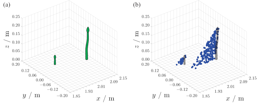
  • acquire asparagus: the package handled the detection of asparagus locations, using sensors; it included programs for reading and converting data from a laser scanner, generating point clouds, and extracting asparagus from them.
A schematic representation of high-level control is depicted in Figure 5.
By organizing the system into these packages, the ROS architecture encouraged modularity, encapsulation, and efficient coordination among the asparagus-picking robot system’s components.
  • Delta robot kinematics
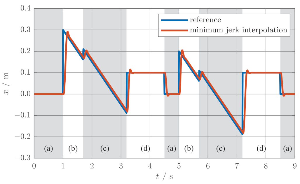
The delta robot was made up of three identical serial mechanisms (arms) that were parallel in construction. For each arm, there were three separate controls, which could be used to operate the robot: this required determining the desired position of each motor, relative to the desired position of the robot’s TCP.
Inverse kinematics [35] was required for this purpose. The following was the solution for a single arm. In Figure 6, all relevant geometry variables are marked. We defined the vector D = [ D x , D y , D z ] T that extended from the position of the motor p 1 to the position of the joint on the TCP platform of the same arm p 3 . The projection L 2 of the second arm segment, with length L 2 , onto the plane perpendicular to the axis of rotation of the first segment, could be calculated as follows:
L 2 = L 2 2 p 1 , y 2 .
Next, we determined the projection D of the vector D onto the same plane:
D = D x 2 + D z 2 .
To determine the angle α between the first segment with a length of L 1 and the vector D , we used the cosine theorem:
L 2 2 = L 1 2 + D 2 2 L 1 D cos α ;
α = arccos L 2 2 L 1 2 D 2 2 L 1 D .
The angle γ described the angle between the vector D and the position of the first segment at an angle of 0 :
γ = arctan D z D x .
From the angles α and γ , the joint value q could be determined:
q = γ α .
To facilitate the aforementioned method, it was necessary to define vectors D in the coordinate system of each arm. The D vectors were defined as follows:
D 1 = a + R 1 T x T C P + b ;
D 2 = a + R 2 T x T C P + b ;
D 3 = a + R 3 T x T C P + b ,
where
R 1 = cos 0 sin 0 0 sin 0 cos 0 0 0 0 1 ;
R 2 = cos 3 π 4 sin 3 π 4 0 sin 3 π 4 cos 3 π 4 0 0 0 1 ;
R 3 = cos 3 π 4 sin 3 π 4 0 sin 3 π 4 cos 3 π 4 0 0 0 1 ;
a = 0.150 0 0 T ;
b = 0.065 0 0 T .
Here, x T C P represented the desired position of the robot’s TCP, R represented the rotation matrices describing the rotation of each arm about the z axis of the base coordinate system, and a and b represented translations from the base coordinate system to the first joint of the arm p 1 (a translation of 150 mm along the x axis), and from the TCP coordinate system to the last joint of the arm p 3 (a translation of 65 mm along the x axis). By employing the aforementioned method, all three joint angles could be calculated, thereby yielding the joint angles corresponding to the desired robot position.
  • Trajectory planning
During asparagus harvesting, a delta robot attached to a mobile platform must compensate for platform motion. In other words, while the platform is in motion, the robot grippers must remain stationary, relative to the global coordinate system: to accomplish this, the delta robot’s reference position must be dynamically determined in each control loop.
First, we determined the coordinate with the greatest range of motion, denoted x f , in order to reach the desired position; on the basis of this, and the maximum velocity of the TCP x ˙ max , we calculated the time necessary to complete the motion, denoted by t f :
t f = t + x f x x ˙ max .
As the desired position could change while the platform was in motion, this parameter had to be constantly updated, to ensure that the robot’s trajectory was maintained accurately.
In order to meet this requirement, the robot’s trajectory was generated using a minimum jerk interpolation method [36]. The expression (20) describes the calculation of the TCP’s jerk x :
x = 9 x ¨ Δ t + 36 x ˙ Δ t 2 + 60 x f x Δ t 3 ;
Δ t = t f t
Here, Δ t represented the difference between the final time t f and the current time t.
Figure 7 is an illustration of the minimum jerk interpolation for the x coordinate in the system of the delta robot during asparagus harvesting. The reference values for regions (b) and (c), in which the asparagus was virtually moving in relation to the mobile platform, were modified based on the platform’s velocity. In the idle state (case a), and during the deposition of harvested spears into the container, the reference remained constant, as these positions were fixed in the mobile platform’s coordinate system.
We acquired the TCP’s acceleration x ¨ , velocity x ˙ , and position x by employing the three-step Euler integration method. Inverse kinematics was utilized, to convert the desired robot position into joint coordinates. Subsequently, an external proportional–derivative controller used these joint values. The controller computed and transmitted to the low-level controller the desired joint velocities via ADS communication.
  • Manual control
A Logitech F710 wireless gamepad was used as the manual control interface. The buttons and joysticks on the gamepad were assigned specific functions, such as controlling the movement and velocity of the mobile platform, and manipulating the delta robot and gripper. We implemented a dedicated safety button that required continuous activation during platform movement, to ensure operational safety. This safety mechanism allowed for the swift cessation of platform motion in the event of uncontrolled movements or loss of connection to the controller.

2.3. Asparagus Spears Detection

A SICK LMS111 outdoor 2D LiDAR sensor was used to detect the asparagus spears. The working range of the LMS111 was 0.5 m to 20 m, and it had a scanning resolution of 0 . 25 and a scanning frequency of 25 Hz. The sensor was attached to the front of a mobile platform, pointing in the opposite direction of the vehicle’s motion. The sensor was positioned at an angle of 45 relative to the y axis of the mobile platform, and at an appropriate height, to ensure that the spears fell within the LMS111’s minimum working range. The linear resolution of the sensory system was 1.1 mm. Figure 8 illustrates an example of the scanned data: as can be seen, the operation principle of the sensor produced noticeable shadows.
A laser scanner only provides distance data on a single plane; therefore, a 3D measurement is required, to determine the position and height of an object, such as an asparagus spear. To obtain this measurement, we created a joint point cloud, by combining data from the laser scanner with odometry data from the mobile platform. We converted the data from the cylindrical coordinate system utilized by the LMS111 to a global Cartesian coordinate system. The laser data was triggered by position, and sampled every 1 mm of mobile platform movement, resulting in a measurement independent of speed. In each direction, the spatial resolution of the measurement system was approximately 1 mm.
The obtained point cloud was altered, to include only the region of interest between two tracks. This updated point cloud was then discretized in the xy plane, with a 20 mm step, resulting in the creation of a grid matrix for z values. As shown in Figure 9, for each discrete field, the sum of the z axis points was computed. To minimize the impact of potential weeds or other objects on the asparagus detection, only z values above 0.05 m were used at this stage. Afterward, the macro-locations of the spears were determined, by comparing the obtained values to a predetermined threshold.
Based on the previously detected field within the xy grid matrix, the micro-location of the spear was determined. Figure 10a,b depict the z values below 50 mm above the soil level, which were used to confirm the spear’s potential growth location. The aggregate of these z values had to exceed a predetermined threshold. The center of the spear was then determined, by calculating the median of the x and y values in the field of interest in the grid matrix (Figure 10c).
As the final step, we examined the z values within a 30 mm radius of the spear’s position, to confirm that it was of harvestable height (the threshold height for harvested spears was set to 150 mm). The positions of confirmed spears were converted to the coordinate system of the delta robot, and sent to a trajectory planning algorithm, to generate a harvesting path.

2.4. Harvesting Procedure

The asparagus harvesting algorithm optimized the process, by taking a number of variables into account, to ensure controlled and efficient harvesting. The algorithm began by detecting the locations where asparagus was growing, and, based on its height, determining whether or not it was suitable for harvesting. These growth locations, obtained in a fixed global coordinate system, were essential for harvesting purposes.
The algorithm initiated linear motion of the platform, and employed a laser scanner to generate a point cloud, in order to plan the gripper’s trajectory. Then, an algorithm for point cloud segmentation was used, to detect the presence of asparagus, and to confirm the availability of growth locations. If no suitable growth locations were identified, or if the asparagus detected was too small, the delta robot returned to its initial position.
After a suitable asparagus had been identified, the algorithm planned the trajectory, using a FIFO system, harvesting the asparagus in the order in which it was identified. To prevent duplicate harvesting, the algorithm compared the distances between harvested and detected asparagus in the xy plane, using the Euclidean distance formula.
As an additional safety measure, the algorithm verified whether adjacent asparagus were too close to the target asparagus, which could impede successful harvesting, due to the gripper’s size. This also ensured sufficient picking space in front of the desired asparagus. Upon detecting an obstruction, the algorithm modified the picking angle, until a clear path was found.
The resulting trajectory for harvesting asparagus included three points: the initial point for approaching the asparagus at picking height; the final point, where the asparagus was growing; and an intermediate point halfway between the initial and final points.
Once the picking points had been determined, the manipulator executed its movements, using interpolation with jerk minimization. The sequence of movements included the mobile platform moving along the asparagus row, opening and closing the gripper, moving to the starting point, reaching the desired points, compensating for velocity during gripper closure, lifting the harvested asparagus, storing it in a container, and releasing the gripper.
The algorithm optimized the asparagus harvesting process, by taking into account constraints, such as the size of the asparagus, its proximity to other asparagus, and the space available for picking. By incorporating these variables, the algorithm ensured efficient and controlled harvesting, thereby boosting overall output.

3. Testing of Asparagus Harvesting

The robotic system for asparagus harvesting underwent testing in a controlled laboratory environment, employing plastic 3D-printed models of asparagus (see Figure 11a). Subsequently, the robot was further tested outdoors, on an actual asparagus field, as depicted in Figure 11b.

3.1. Laboratory Testing

We carried out 10 harvesting repetitions on a 2.5 -m-long row containing 16 asparagus spears of various shapes (straight, curved) and heights (10 spears > 15 cm, 6 spears < 15 cm). To replicate real-world conditions as closely as possible, we spread garden soil on the ground. In total, a 25-m-long test polygon, with 100 harvest-ready spears and 60 spears below harvesting height, was used. Each repetition involved the random placement of spears in a non-uniform pattern. A test setup example is depicted in Figure 12.
The speed of the platform was manually set to approximately 60 mm/s for each repetition: at that speed, the robotic system was able to detect and harvest spears, even if two spears were placed next to one another, while maintaining continuous motion. Due to hardware limitations, the mobile platform included stop-and-go motion, in order to collect all spears if the platform’s speed increased.
The laboratory test results, as shown in Table 1, indicate a 94% detection rate for all the asparagus, with only 6 of the 100 harvest-ready spears going undetected, due to their close proximity, causing them to be treated as a single spear (see Figure 12). Of the harvest-ready spears, 88% were successfully detected and collected; however, there were six instances in which spears were detected but not harvested, due to inaccurate harvesting point determination. No small spears were harvested.
The total completion time for all 10 repetitions was 423 s, excluding robot return times. The harvesting cycle cost 3.44 s ± 0.14 s (mean ± standard deviation), from the detection of the spear to the transfer and release of the spear into the storage container.

3.2. Field Testing

Testing was conducted on an asparagus field at the Biotechnical Faculty of the University of Ljubljana, Slovenia, that is used solely for research. The robot was tested on a single row measuring 25 m in length and 1 m in width. Prior to harvesting, there were a total of 57 asparagus spears, of which 43 were ripe for picking, and 14 were deemed insufficiently developed.
The settings of the robot remained identical to those used during the laboratory testing. The robot traversed the length of the field in a single pass at a speed of approximately 60 mm/s. The robot successfully harvested 33 of the 43 mature asparagus spears, accounting for 77% of the total harvest. In addition, 6 out of the 43 correctly identified spears were not harvested (14%). The clustering of missed spears led to the identification of a single spear with the harvesting point positioned in the middle. A further 4 out of the 43 spears ripe for picking were not identified at all (9%): the growth of these spears was poor, as they were either severely twisted or aligned parallel to the ground. In such cases, the detection algorithm classified the spears unsuitable for harvest, because they did not meet the predetermined height threshold. There were no too-small spears harvested.

4. Discussion

This article describes a lightweight agricultural robot designed specifically for green asparagus harvesting. For efficient spear harvesting, the robot system consists of a tracked mobile platform and a delta robot. The delta robot significantly reduces picking times (below 3.5 s) when compared to serial mechanisms [24,28].
The results from the study indicate that the recognition rate in laboratory tests was 94%, which is comparable to [33]; however, six spears were not recognized, because there were instances in which spears were placed too closely together, causing the algorithm to mistake two separate spears for a single spear. This issue, of detecting a single spear as opposed to multiple spears, was also responsible for the failure to collect some spears. In the laboratory experiment, the overall rate of harvest was 88%. The incorrect determination of the picking point resulted in a few misses. When two or more spears were grouped together, the harvesting point was incorrectly determined to be in the middle of the spears, resulting in harvesting next to the spear rather than at the spear. Another potential error was the density of spears, causing the robot to be too slow in picking all of them. At this stage, the stop-and-go method must be utilized to address this issue.
In an open field, the spear recognition rate was 91%, while the harvesting success rate was 77%. The lower success rate compared to the laboratory tests was due to the various growth patterns and spear shapes. The issues with harvesting are attributable to the detection method that is currently in use: when spears are closely spaced, overlap, or grow at varying angles, this method becomes ineffective. Because the grasping point is determined in the middle, two asparagus spears that are close together may be misidentified as a single spear, leading to a missed harvest. In addition, if spears are twisted or growing at an angle, the point cloud segmentation method generates inaccurate gripping points, due to an increased number of detected points where the spear is straight, typically at the spear’s tip, as opposed to its base. Furthermore, severely tilted spears may not meet the height requirement for harvest readiness, and are therefore incorrectly processed as not harvest-ready.
The majority of harvesting mechanisms [24,26,28] can only approach spears from one side, preventing them from avoiding small spears or other obstacles. Funami et al. [25] presented a partial solution, by introducing a SCARA-type robot that allows the tool’s orientation to be set; however, the issue persists, as the mechanism’s segments can still harm other spears. In our design, the robot’s gripper incorporates an additional degree-of-freedom, enabling orientation changes and the harvesting of asparagus from different angles. This feature prevents damage to young spears, which would otherwise inhibit plant growth, because the spear releases growth-stimulating enzymes when it reaches a height of 12 cm or more.
For spear detection, a laser scanner was employed, similar to the approach used by Sakai et al. [31], where spears were scanned vertically from the ground to the top. The point cloud generated by the combination of 2D laser scans and odometry eliminated the need for an RGBD camera. This system is anticipated to operate reliably throughout the day, irrespective of lighting conditions. Utilizing a straightforward method of point cloud segmentation, the optimal picking points were determined. This approach is suitable for systems with limited computational capability, such as Raspberry Pi, operating in real time.
Based on the robot’s test speed of 0.06 m/s, a single robot is capable of harvesting approximately 2000 m of asparagus rows in 10 h. Taking into account the operational limitations of the robot, this corresponds to an estimated harvest of approximately 8.000 spears, which exceeds the results of Sakai et al. [31], who estimated a harvest of 6.500 spears in 18 h. Notably, this estimation assumes that the spears are growing approximately 0.2 m apart, that the robot operates continuously, and that approximately 20% of the time is allocated for platform maneuvering, such as turning between rows.
The small size of the robotic system provides numerous benefits. Smaller and lighter autonomous robots are more environmentally friendly than large and heavy farm machinery, because they cause less damage to arable land. In addition, smaller robots are typically more cost-effective, enabling the deployment of multiple small robots for the price of a single large robot.
On the basis of test-identified deficiencies, future work should involve enhancing the detection system with additional low-cost modalities, to further enhance asparagus detection. As suggested by Leu et al. [28], a combination of RGB and laser technologies could be utilized, to improve the system’s ability to detect and identify asparagus spears. Priority should also be given to the implementation of AI methods, in order to increase the detection success of asparagus with varying shapes. Efforts should be made to improve design and functionality, in order to make harvesting operations faster and more efficient. In instances where there is a large cluster of spears, speed adaptation should be implemented, to ensure thorough picking, with the mobile platform adjusting its speed, or even coming to a complete stop, to collect all spears within the cluster. In addition, an RTK GPS (real-time kinematics GPS) system should be considered, for mapping the locations of small asparagus spears, which would provide valuable information for future harvesting. The system could be expanded to harvest a variety of stem vegetables, including leeks and celery, with minimal modifications; furthermore, it is adaptable to tasks other than vegetable harvesting, such as flower picking.
In addition, the mobile robot system could be augmented by additional capabilities, to address common issues in asparagus fields, such as weed control. Mechanical weeding is not feasible, as it can damage underground spears. Integrating non-contact weeding options, such as laser weed [9] or flame weeders [37], into the robot system is one potential solution.
The short harvesting season for asparagus (typically up to nine weeks) necessitates alternative business models, in light of the substantial financial investment required for agricultural robots. Exploring additional modalities, or offering the robot as a service in which the system can be rented for a fee, would increase its economic viability. Therefore, the presented platform serves as the basis for the development of a multifunctional robot that can be used throughout the entire growing season.

5. Conclusions

This paper introduced a specialized asparagus harvesting robot system that effectively addresses the challenges posed by spear growth variability. The design consists of a tracked mobile platform outfitted with a delta robot for harvesting individual spears. The additional rotation of the gripper enables the robot to harvest spears from the optimal direction. The system demonstrated a high rate of success in both laboratory and field settings. The robot’s diminutive size provides environmental and financial benefits, while potential enhancements extend its utility. In conclusion, this research significantly improves asparagus harvesting’s productivity and sustainability, ensuring the availability of high-quality produce.

Author Contributions

Conceptualization, S.Š. and M.M. (Matjaž Mihelj); data curation, S.Š.; formal analysis, S.Š.; funding acquisition, M.M. (Marko Munih); investigation, S.Š. and M.M. (Matjaž Mihelj); methodology, S.Š. and M.M. (Matjaž Mihelj); project administration, M.M. (Marko Munih) and M.M. (Matjaž Mihelj); resources, M.M. (Marko Munih); software, S.Š. and M.M. (Matjaž Mihelj); supervision, M.M. (Marko Munih); validation, S.Š.; visualization, S.Š.; writing—original draft, S.Š.; writing—review and editing, S.Š., M.M. (Marko Munih) and M.M. (Matjaž Mihelj). All authors have read and agreed to the published version of the manuscript.

Funding

This research was supported by the Slovenian Research Agency (ARRS), under the research program “Motion analysis and synthesis in man and machine” (P2-0228).

Conflicts of Interest

The authors declare no conflict of interest.

Abbreviations

The following abbreviations are used in this manuscript:
CNNconvolutional neural network
FRCNNfaster, region-based convolutional neural network
SSDsingle shot detection
RCNNregion-based convolutional neural network
TCPtool center point
ADSautomation device specification
ROSRobot Operating System
RGBDred–green–blue–depth
GPSGlobal Positioning System
RTK GPSreal-time kinematics GPS

References

  1. Marinoudi, V.; Sørensen, C.G.; Pearson, S.; Bochtis, D. Robotics and labour in agriculture. A context consideration. Biosyst. Eng. 2019, 184, 111–121. [Google Scholar] [CrossRef]
  2. Kushwaha, H.; Sinha, J.; Khura, T.; Kushwaha, D.K.; Ekka, U.; Purushottam, M.; Singh, N. Status and scope of robotics in agriculture. In Proceedings of the International Conference on Emerging Technologies in Agricultural and Food Engineering, Kharagpur, India, 27–30 December 2016; Volume 12, p. 163. [Google Scholar]
  3. Mahmud, M.S.A.; Abidin, M.S.Z.; Emmanuel, A.A.; Hasan, H.S. Robotics and automation in agriculture: Present and future applications. Appl. Model. Simul. 2020, 4, 130–140. [Google Scholar]
  4. Lytridis, C.; Kaburlasos, V.G.; Pachidis, T.; Manios, M.; Vrochidou, E.; Kalampokas, T.; Chatzistamatis, S. An overview of cooperative robotics in agriculture. Agronomy 2021, 11, 1818. [Google Scholar] [CrossRef]
  5. Bergerman, M.; Billingsley, J.; Reid, J.; van Henten, E. Robotics in agriculture and forestry. Springer Handbook of Robotics; Springer: Cham, Switzerland, 2016; pp. 1463–1492. [Google Scholar]
  6. Lowenberg-DeBoer, J.; Huang, I.Y.; Grigoriadis, V.; Blackmore, S. Economics of robots and automation in field crop production. Precis. Agric. 2020, 21, 278–299. [Google Scholar] [CrossRef] [Green Version]
  7. Avgoustaki, D.D.; Avgoustakis, I.; Miralles, C.C.; Sohn, J.; Xydis, G. Autonomous Mobile Robot with Attached Multispectral Camera to Monitor the Development of Crops and Detect Nutrient and Water Deficiencies in Vertical Farms. Agronomy 2022, 12, 2691. [Google Scholar] [CrossRef]
  8. Zhang, W.; Miao, Z.; Li, N.; He, C.; Sun, T. Review of Current Robotic Approaches for Precision Weed Management. Curr. Robot. Rep. 2022, 3, 139–151. [Google Scholar] [CrossRef]
  9. Morara, G.; Baldassarri, A.; Diepenbruck, J.; Bruckmann, T.; Carricato, M. Design of a Weed-Control Mobile Robot Based on Electric Shock. In Proceedings of the Symposium on Robot Design, Dynamics and Control, Udine, Italy, 4–7 July 2022; pp. 220–227. [Google Scholar]
  10. Iida, M.; Harada, S.; Sasaki, R.; Zhang, Y.; Asada, R.; Suguri, M.; Masuda, R. Multi-combine robot system for rice harvesting operation. In Proceedings of the 2017 ASABE Annual International Meeting, Spokane, WA, USA, 16–19 July 2017; p. 1. [Google Scholar]
  11. Rong, J.; Fu, J.; Zhang, Z.; Yin, J.; Tan, Y.; Yuan, T.; Wang, P. Development and Evaluation of a Watermelon-Harvesting Robot Prototype: Vision System and End-Effector. Agronomy 2022, 12, 2836. [Google Scholar] [CrossRef]
  12. Roldán, J.J.; del Cerro, J.; Garzón-Ramos, D.; Garcia-Aunon, P.; Garzón, M.; De León, J.; Barrientos, A. Robots in agriculture: State of art and practical experiences. In Service Robots; IntechOpen: Rijeka, Croatia, 2018; pp. 67–90. [Google Scholar]
  13. Kitić, G.; Krklješ, D.; Panić, M.; Petes, C.; Birgermajer, S.; Crnojević, V. Agrobot Lala—An Autonomous Robotic System for Real-Time, In-Field Soil Sampling, and Analysis of Nitrates. Sensors 2022, 22, 4207. [Google Scholar] [CrossRef]
  14. Blender, T.; Buchner, T.; Fernandez, B.; Pichlmaier, B.; Schlegel, C. Managing a mobile agricultural robot swarm for a seeding task. In Proceedings of the IECON 2016-42nd Annual Conference of the IEEE Industrial Electronics Society, Florence, Italy, 23–26 October 2016; pp. 6879–6886. [Google Scholar]
  15. Hallik, L.; Šarauskis, E.; Kazlauskas, M.; Bručienė, I.; Mozgeris, G.; Steponavičius, D.; Tõrra, T. Proximal Sensing Sensors for Monitoring Crop Growth. In Information and Communication Technologies for Agriculture—Theme I: Sensors; Springer: Cham, Switzerland, 2022; pp. 43–97. [Google Scholar]
  16. Cruz Ulloa, C.; Krus, A.; Barrientos, A.; Del Cerro, J.; Valero, C. Robotic fertilisation using localisation systems based on point clouds in strip-cropping fields. Agronomy 2020, 11, 11. [Google Scholar] [CrossRef]
  17. Hassan, A.; Abdullah, H.M.; Farooq, U.; Shahzad, A.; Asif, R.M.; Haider, F.; Rehman, A.U. A wirelessly controlled robot-based smart irrigation system by exploiting arduino. J. Robot. Control (JRC) 2021, 2, 29–34. [Google Scholar] [CrossRef]
  18. Tourrette, T.; Deremetz, M.; Naud, O.; Lenain, R.; Laneurit, J.; De Rudnicki, V. Close coordination of mobile robots using radio beacons: A new concept aimed at smart spraying in agriculture. In Proceedings of the 2018 IEEE/RSJ International Conference on Intelligent Robots and Systems (IROS), Madrid, Spain, 1–5 October 2018; pp. 7727–7734. [Google Scholar]
  19. Conesa-Muñoz, J.; Bengochea-Guevara, J.M.; Andujar, D.; Ribeiro, A. Route planning for agricultural tasks: A general approach for fleets of autonomous vehicles in site-specific herbicide applications. Comput. Electron. Agric. 2016, 127, 204–220. [Google Scholar] [CrossRef]
  20. Kootstra, G.; Wang, X.; Blok, P.M.; Hemming, J.; Van Henten, E. Selective harvesting robotics: Current research, trends, and future directions. Curr. Robot. Rep. 2021, 2, 95–104. [Google Scholar] [CrossRef]
  21. Peebles, M.; Lim, S.H.; Duke, M.; Au, C.K. Overview of sensor technologies used for 3D localization of asparagus spears for robotic harvesting. Appl. Mech. Mater. 2018, 884, 77–85. [Google Scholar] [CrossRef]
  22. Peebles, M.; Barnett, J.; Duke, M.; Lim, S.H. Robotic Harvesting of Asparagus using Machine Learning and Time-of-Flight Imaging–Overview of Development and Field Trials. In Proceedings of the 2020 IEEE 16th International Conference on Automation Science and Engineering (CASE), Hong Kong, 20–21 August 2020; pp. 1361–1366. [Google Scholar]
  23. Irie, N.; Taguchi, N.; Horie, T.; Ishimatsu, T. Asparagus harvesting robot coordinated with 3-D vision sensor. In Proceedings of the 2009 IEEE International Conference on Industrial Technology, Churchill, VIC, Australia, 10–13 February 2009; pp. 1–6. [Google Scholar]
  24. Irie, N.; Taguchi, N. Asparagus harvesting robot. J. Robot. Mechatron. 2014, 26, 267–268. [Google Scholar] [CrossRef]
  25. Funami, Y.; Kawakura, S.; Tadano, K. Development of a Robotic Arm for Automated Harvesting of Asparagus. Eur. J. Agric. Food Sci. 2020, 2, 1–10. [Google Scholar] [CrossRef] [Green Version]
  26. Zhang, R.; Zhu, L.; Yang, S.; Yao, H. Design of self-propelled asparagus mechanized harvesting device. J. Phys. Conf. Ser. 2020, 1601, 062003. [Google Scholar] [CrossRef]
  27. Zichen, H.; Saki, S. Research Progress and Enlightenment of Japanese Harvesting Robot in Facility Agriculture. Smart Agric. 2022, 4, 135. [Google Scholar]
  28. Leu, A.; Razavi, M.; Langstädtler, L.; Ristić-Durrant, D.; Raffel, H.; Schenck, C.; Gräser, A.; Kuhfuss, B. Robotic green asparagus selective harvesting. IEEE/ASME Trans. Mechatron. 2017, 22, 2401–2410. [Google Scholar] [CrossRef]
  29. Peebles, M.; Lim, S.; Duke, M.; McGuinness, B. Investigation of optimal network architecture for asparagus spear detection in robotic harvesting. IFAC-PapersOnLine 2019, 52, 283–287. [Google Scholar] [CrossRef]
  30. Kennedy, G.; Ila, V.; Mahony, R. A perception pipeline for robotic harvesting of green asparagus. IFAC-PapersOnLine 2019, 52, 288–293. [Google Scholar] [CrossRef]
  31. Sakai, H.; Shiigi, T.; Kondo, N.; Ogawa, Y.; Taguchi, N. Accurate position detecting during asparagus spear harvesting using a laser sensor. Eng. Agric. Environ. Food 2013, 6, 105–110. [Google Scholar] [CrossRef]
  32. Hong, W.; Ma, Z.; Ye, B.; Yu, G.; Tang, T.; Zheng, M. Detection of Green Asparagus in Complex Environments Based on the Improved YOLOv5 Algorithm. Sensors 2023, 23, 1562. [Google Scholar] [CrossRef]
  33. Liu, X.; Wang, D.; Li, Y.; Guan, X.; Qin, C. Detection of Green Asparagus Using Improved Mask R-CNN for Automatic Harvesting. Sensors 2022, 22, 9270. [Google Scholar] [CrossRef]
  34. Mihelj, M.; Bajd, T.; Ude, A.; Lenarčič, J.; Stanovnik, A.; Munih, M.; Rejc, J.; Šlajpah, S. Robotics; Springer: Cham, Switzerland, 2019. [Google Scholar]
  35. Zsombor-Murray, P. Descriptive Geometric Kinematic Analysis of Clavel’s “Delta” Robot; Centre of Intelligent Machines, McGill University: Montreal, QC, Canada, 2004; Volume 1. [Google Scholar]
  36. Piazzi, A.; Visioli, A. Global minimum-jerk trajectory planning of robot manipulators. IEEE Trans. Ind. Electron. 2000, 47, 140–149. [Google Scholar] [CrossRef] [Green Version]
  37. Martelloni, L.; Fontanelli, M.; Frasconi, C.; Raffaelli, M.; Pirchio, M.; Peruzzi, A. A combined flamer-cultivator for weed control during the harvesting season of asparagus green spears. Span. J. Agric. Res. 2017, 15, e0203. [Google Scholar] [CrossRef]
Figure 1. The delta robot consists of three parallel arms driven by servo motors, and an additional rotational axis for gripper orientation control.
Agronomy 13 01766 g001
Figure 2. The gripper comprised three components: a rigid finger (red part) for supporting the asparagus spear; a flexible finger (yellow part) that conformed to the spear’s size, for a firm grip; and a blade for cutting the spear. An illustration of the grasping procedure is shown on the right.
Agronomy 13 01766 g002
Figure 3. Mobile platform with integrated delta robot and laser scanner Sick LMS111.
Agronomy 13 01766 g003
Figure 4. Control scheme for the asparagus harvesting robot: low-level control for motor velocity control; high-level control for providing trajectories with manual control capability.
Agronomy 13 01766 g004
Figure 5. Schematic representation of high-level control, based on ROS. The main functionalities were covered by four packages: Beckhoff communication, for communication with PLC; mobile platform, for control of the mobile robot; delta robot, covering the modalities for the delta robot; and acquire asparagus, for processing sensory data and asparagus detection.
Agronomy 13 01766 g005
Figure 6. Variables of the delta robot’s geometry, used to determine the inverse kinematics. The respective colors for the base coordinate system, the TCP coordinate system, and the individual arm coordinate systems were green, red, and blue.
Agronomy 13 01766 g006
Figure 7. Minimum jerk interpolation for x coordinate in the delta robot’s system during asparagus harvesting: (a) robot is in idle state, positioned in the middle; (b) asparagus detection triggers a movement of 50 mm ahead of the asparagus (reference value is adjusted, based on the mobile platform velocity of 0.2 m/s); (c) robot moves forward by 50 mm, to grasp and cut the asparagus; (d) robot transports the harvested spear to the fixed storage container, and releases it (reference position is fixed, as container is mounted on the mobile platform).
Agronomy 13 01766 g007
Figure 8. Scanned data of two asparagus spears: (a) positions of the asparagus spears; (b) scanned data with surroundings (soil, robot tracks) filtered out.
Agronomy 13 01766 g008
Figure 9. Grid discretization visualization of two asparagus spears: (a) green dots representing data used for analysis; (b) blue squares marking two local maximums in the discretized grid matrix.
Agronomy 13 01766 g009
Figure 10. Visualization of calculated gripping position for two asparagus spears, using grid discretization, with (a) red dots representing analyzed data, (b) blue squares marking local maximums in the discretized grid matrix, and (c) crosses indicating calculated spear positions, based on medians of previously selected grid positions (green cross: asparagus is ripe for harvest; red cross: asparagus is too small).
Agronomy 13 01766 g010
Figure 11. Mobile platform during tests (a) on a simulated field in the laboratory, and (b) on the test asparagus field at Biotechnical Faculty, University of Ljubljana, Slovenia.
Agronomy 13 01766 g011
Figure 12. Example of a test setup for one repetition. A total of 10 fully grown spears and 6 smaller spears were randomly placed in a field measuring 2 m × 0.55 m . A red square indicates a problematic situation, where one asparagus was covered by another, causing the detection algorithm to identify them as a single spear.
Agronomy 13 01766 g012
Table 1. Results of laboratory and outdoor field tests: spears ready to harvest; recognized/unrecognized spears; harvested spears; missed spears, length of the test field; and total time required. The relative rate, expressed as a percentage of the total number of spears ready to harvest, is indicated within the brackets.
Spears Ready to HarvestTotal
Length/m
Total
Time/s
TotalRec. aUnrec. bHarvestedMissed
laboratory10094 (94%)6 (6%)88 (88%)6 (6%)25423
outdoor field4339 (91%)4 (9%)33 (77%)6 (14%)25437
a recognized, b unrecognized.
Disclaimer/Publisher’s Note: The statements, opinions and data contained in all publications are solely those of the individual author(s) and contributor(s) and not of MDPI and/or the editor(s). MDPI and/or the editor(s) disclaim responsibility for any injury to people or property resulting from any ideas, methods, instructions or products referred to in the content.

