Article

Development of an Attitude Adjustment Crawler Chassis for Combine Harvester and Experiment of Adaptive Leveling System

School of Agricultural Engineering, Jiangsu University, Zhenjiang 212013, China
*
Author to whom correspondence should be addressed.
Agronomy 2022, 12(3), 717; https://doi.org/10.3390/agronomy12030717
Submission received: 9 February 2022 / Revised: 11 March 2022 / Accepted: 14 March 2022 / Published: 16 March 2022

Abstract

:
Body tilt is typically unavoidable for agricultural vehicles or platforms when operated over tough terrain in agricultural production, and, therefore, it is not possible to guarantee the operation performance. Current leveling methods mainly focus on wheeled vehicles or adjustment for single working parts rather than the vehicle body, and few of them could be applied to crawler vehicles. The objective of this research was to put forward an adaptive leveling system for combine harvesters based on the development of a new four-point lifting adjustable crawler chassis. The working principle of the proposed adjustable mechanism was studied on the basis of the analysis of adjustment characteristics under multiple posture adjustment conditions in a RecurDyn environment. The design relies on the combination of the attitude detection of the leveling system and adjustment calculation of driving hydraulic cylinders according to the established mathematical models. Within the designed adjustable extent (including adjustment range of vehicle height 0–87.8 mm, lateral inclination ±3.98° and longitudinal inclination −2.9–5.2°), the leveling performance of lateral and longitudinal inclination was then tested separately. The experiment showed that the leveling system could achieve automatic leveling with an accuracy of ±0.4° and could provide technical support for the development of crawler vehicles.

1. Introduction

A combine harvester is a product with one of the most complex structures of all agricultural vehicles [1]. The walking chassis is the core component of a combine harvester, which is installed with all the working devices to complete the functions of cutting, conveying, threshing, cleaning, grain gathering, smashing and spraying, but also needs to adapt to various operating environments, such as paddy or dry fields and slopes [2,3,4]. However, vehicles are usually unable to maintain a level position when operated over uneven terrain, which frequently requires the driver to adjust the operating parameters to improve the harvester performance [5,6,7].
The common walking systems, wheeled, crawler and wheeled-crawler combination structures, have been widely applied to various agricultural machines. Wheeled vehicles have a more flexible transfer performance when it comes to long-distance operations, owing to their excellent driving speed. However, compared with the crawler walking system, which integrates the outstanding advantages of large ground contact area, low ground pressure and strong ability to cross trenches and ridges [8,9,10], wheeled vehicles can hardly adapt to operations on damp and soft ground. Thus, crawler structures have received increasing interest for the improvement of operation adaptability, and this type accounts for 70% of grain combine harvesters sold in China in 2019.
At present, the mainstream crawler combine harvesters in China mainly adopt the chassis with a welded structure, as shown in Figure 1. As the chassis frame and walking devices on both sides are welded into a whole through multiple fixed beams, the structure strength of the chassis can be enhanced. However, such kind of structure limits the adjustment of the body posture, resulting in the following problems in the harvesting process: The characteristics of the paddy field in terms of soil viscosity, moisture content, mud foot depth and topographical level drop are greatly different so that the harvester is easy to tilt in the direction of lateral or longitudinal; Moreover, the fields in the southern part of China are mostly small and scattered with many ridges [11]. When it comes to cross-regional operations and that have cross ridges, pits, or field transfers and loading, excessive change in vehicle inclination could make the harvester in major danger of tipping [12,13].
In recent years, the safety of agricultural vehicles driving in fields has attracted the attention of many experts. Dieumet et al. [14] proposed an online adaptive observer. Terrain and vehicle parameters could be updated to take into account the effects of changes in the center of gravity height and total vehicle mass, on the basis of which it could successfully access and avoid rollover risk for agricultural vehicles when moving in terrain with important slopes. Farzaneh et al. [15] investigated design and installation methods of Crush Protection Devices (CPDs) on a variety of all-terrain vehicles and evaluated the safety of the CPDs based on factors, such as shape, volume and installation height, to reduce the injury to operators from rollover accidents. In order to prevent rollover and maintain safe operations on unstructured terrain, Zhu et al. [16] put forward a multi-sensor-based approach to the active attitude prediction of agricultural vehicles. The terrain information in front of the vehicle could be acquired through LiDAR, IMU and encoders, and then tire grounding points could be calculated by the combination of predicted vehicle position for vehicle attitude prediction (pitch and roll angles). Verification experiments proved that the above methods could improve the driving stability of agricultural vehicles to some extent; however, it is unavoidable for agriculture vehicles to encounter complex, uneven production roads. Therefore, it is of great significance to improve the adaptability of the vehicle body by implementing adaptive leveling.
Currently, vehicle leveling technology has received increasing interest from researchers. The active suspension of vehicles can adjust dynamically and adaptively according to the motion state and road condition of the vehicles and improve the trafficability by controlling the body height. Sarel et al. [17] used slow active suspension control to reduce body roll so as to reduce the possibility of rollover tendency in the case of lane change and sudden change in vehicle conditions. Sun et al. [18] controlled the vehicle height by fuzzy sliding mode controller (FSMC) and adjusted the vehicle’s heeling and pitch angle through the EAS system, which effectively guaranteed the vehicle height adjustment performance. In the field of special vehicles, the Mars rover Zhurong designed by Pan et al. [19] realized the functions of peristaltic wheel walking and horizontal lifting of the vehicle body by using the active suspension system, which solves the problems of a low climbing angle of the planetary vehicle mobile system in soft terrain. Sun et al. [20] studied a posture adjustment mechanism based on a parallel four-bar mechanism, and key components were analyzed in ANSYS software to meet strength requirements, while it could only complete the lateral level. Edlund et al. [21] designed a new type of bogie to level the operating components to improve the ability of forestry vehicles when traveling on rugged and soft soils.
In addition, research has been carried out on the leveling technology of wheeled combine harvesters by famous agricultural production companies that pose questions about the feasibility of application in crawler vehicles due to the completely different structures between the two walking systems. The wheeled combine harvester produced by the John Deer Company adopted an electro-hydraulic automatic leveling system to achieve vehicle leveling by controlling the break-make of the fuel supply circuit [22]. The AL QUATTRO EVO wheeled wheat harvester [23] produced by the LAVERDA Company can achieve horizontal leveling with a slope less than 21.8° and vertical leveling with a slope less than 16.7°. The combine harvester designed by the CASE IH Company can monitor grain conditions and operation information in real-time and automatically adjust working parts according to field operations [24]. In particular, the vertical uphill and downhill capacity of Fendt 5275 CSL and New Holland CH7.70 combine harvesters can be as high as 35% and 18%, respectively, showing an excellent ability to climb over extreme slopes [25,26].
According to the literature, leveling technology plays a key role in guaranteeing the working stability of agricultural vehicles. However, current research mainly focuses on wheeled vehicles, and there are a few methods of adjusting the chassis of crawler combine harvesters, so the objective of this study is to put forward an adaptive leveling system for combine harvesters based on a new four-point lifting adjustable crawler chassis. The working principle was verified by analyzing the posture adjustment process in a RecurDyn environment, and the required adjustment information of each driving hydraulic cylinder could be calculated through established mathematical models. After the whole adaptive leveling system was integrated into the prototype, the experiment was then carried out.

2. Design of Adaptive Leveling System

2.1. Attitude Adjustment Mechanism

As a key component of the adaptive leveling system, a couple of symmetrically distributed lifting adjustable mechanisms are developed to adjust the chassis attitude. Fixed beams for connecting chassis frame and walking device on both sides in traditional crawler combine harvesters are then replaced. The simplified model of the whole chassis is shown in Figure 2 (without crawler belts in the whole content for obvious observation), and the adjustable mechanism is marked in red.
Figure 2 shows the detailed structure of the adjustable mechanism; each side includes a connecting arm, front oscillating arm assembly, connecting rod, rear pivot arm, rear oscillating arm assembly and hydraulic cylinders. The front oscillating arm assembly with two oscillating arms is fixed by a spline shaft. The rear oscillating arm assembly with pivot arm and crank arm is fixed by a spline shaft as well to make sure there is no relative displacement between them. The other connecting mechanisms are hinged for relative rotation. The connecting arm and rear oscillating arm assemblies are hinged to the walking device. One end of the front hydraulic cylinder is hinged to the chassis frame. The splines of the front and rear oscillating arm assemblies are hinged to the chassis frame. Thus, the lifting apparatus on both sides could connect to the chassis frame and walking device. Furthermore, the thrust wheel and tensioning wheel in the chassis device are fixed to the walking device. The driving wheels are connected to the gearbox semi-axis. The track roller and rear oscillating arm assembly could rotate with the oscillating arm. As the power output of the gearbox, the half shaft is fixed with the frame through the hoop, which means that the gearbox is relatively fixed to the frame, and the change in its attitude will also follow the adjustment of the chassis frame.

2.2. Control System

The main working procedure of the adaptive leveling system is shown in Figure 3. A double-axis inclination sensor (Model: MQJS30V1CC, Shenzhen Miran Technology Co., Ltd., Shenzhen, China) is fixed under the chassis frame, with a frequency of 100 Hz and measurement accuracy of 0.05°, for periodic measurement of vehicle body lateral and longitudinal roll angles. Vehicle attitude then could be obtained by an inclination sensor, and the required displacement could be calculated through a controller on the basis of the input inclination information. The relevant PWM signals are controlled to adjust the action hydraulic cylinder, and feedback adjustments are then conducted according to real displacement monitored through displacement sensors (Model: WY-01-100, Shenzhen Miran Technology Co., Ltd., Shenzhen, China).
The structure of the control system is shown in Figure 4. The BODAS RC28-14 (Model: RC28-14, Bosch Rexroth, Lohr am Main, Germany) controller is the core of the whole control system. The hardware part includes a double-axis inclination sensor, a proportional directional valve and displacement sensors. BODAS RC28-14 is responsible for the communication, sensor integration and calculation of the hydraulic cylinder displacement. The inclination sensor and displacement sensors are powered by the controller and the analog output parameter can be connected with the controller directly through the I/O port. The electrohydraulics are designed to conduct adjustments, and each adjustment action could be driven by four double-action hydraulic cylinders. The hydraulic, one-way valves are set at each oil inlet and outlet of the hydraulic lock and thus prevent insufficient support stiffness.
In this study, the auto-manual switch is used to conveniently enter the automatic adjustment mode, and the green button in Figure 5a is the master switch of the whole system. In addition, manual adjustment is indispensable; therefore, the operation includes an electric handle. As shown in Figure 5b, the upper three buttons are the adjustment buttons for the body posture. The handle cooperates with the function buttons to swing in four directions, front, rear, left and right, so that each button has four adjustment functions. The left and right buttons separately control the front left and front right hydraulic cylinders to achieve lateral adjustment. Swinging to the left is the extension of the hydraulic cylinder and swinging to the right is the contraction of the hydraulic cylinder. The red button in the middle controls the linkage of a group of front hydraulic cylinders or rear hydraulic cylinders. When it swings to the left and right sides, it controls the linkage of the front hydraulic cylinders to realize the overall lifting of the car body; when the handle swings in the forward and backward directions, it controls a group of rear hydraulic cylinders. For the linkage adjustment, swing forward is the extension of the hydraulic cylinder, the body completes a forward tilting action, and the swing to the rear is the hydraulic cylinder shrinking, and the body is adjusted backward.
In order to prevent the cutter in the front of the harvester and the rear frame from colliding with the ground when the chassis adjusts longitudinally, it is necessary to design the range of attitude adjustment reasonably. The longitudinal leveling adjustment range is shown in Figure 6. The coordinate system is established with the horizontal state of the vehicle as to the origin, the longitudinal adjustment angle as the abscissa and the vehicle height as the ordinate.
As illustrated in Figure 6, Area 1 represents that when the vehicle height is below A, the forward tilting adjustment is allowed to be 0°. When the body height is between A and B, the forward action is limited to F1. At this time, the collision between the front cutter of the header and the road or the field can be avoided when the cutter is in the non-working position. Area 2 represents that when vehicle height is below B, the retroversion action is limited to R1 to prevent the rear frame from colliding with the road surface, for the vehicle height is too low. Area 3 shows that when the vehicle height is between C and D, the forward action is now within F3. In addition, when vehicle height is higher than D, the allowable forward tilting and retroversion tilting adjustment angles are 0°, which can prevent the excessive longitudinal tilting angle from leading to an excessive change in the gravity center, thus avoiding excessive driving resistance.
On the basis of the designed attitude adjustment range, the sequence of posture adjustment for the adaptive leveling method is shown in Figure 7.

2.3. Mathematical Models

The chassis attitude adjustment is realized by adjusting the displacement of the hydraulic cylinders to drive the movement of the lifting mechanism. The different combinations of hydraulic cylinders determine the adjustment action, and the specific displacement determines the actual change in vehicle height and inclination state. Therefore, according to the different adjustment requirements, the mathematical model between chassis attitude and the displacement of each hydraulic cylinder under the corresponding conditions is established. The ultimate range of attitude adjustment is studied, and the foundation is further provided for the adaptive leveling control system to calculate the theoretical adjustment amount of the hydraulic cylinder according to the current vehicle attitude.
As can be seen in Figure 8, Points O and N are defined as the center of crucial component joints to facilitate the expression of the key structure. Figure 8a shows the top view of the whole chassis device. The forward direction of the harvester is defined as Y, and the X-direction is perpendicular to the Y-direction. The inclination angle of the vehicle body when tilting laterally (the vehicle body tilts around the Y-direction) is θ1, and the inclination angle of the vehicle body when tilting longitudinally (the vehicle body tilts around the X-direction) is θ2.
When the overall horizontal lifting of the chassis frame is adjusted, as shown in Figure 8b, the left rear and right rear hydraulic cylinders maintain the initial position and ABMN and BDEM form a parallelogram. When the left front and right front hydraulic cylinders are simultaneously extended, the rear arm rotates clockwise so that point M is lifted. Under the influence of the parallelogram mechanism, the rotating arms MN and AO rotate clockwise to achieve the overall lifting of the frame. Therefore, the lifting height of the chassis is the height difference between the rotating arms AB in the vertical direction before and after the rotation. Its theoretical calculation is derived as Equations (1)–(3). The length range of the front hydraulic cylinder FG is 508–578 mm, the overall lifting range of chassis Δ h D can be calculated as 0–87.8 mm and the adjusting range of chassis ground clearance is 353–440.8 mm.
Δ h D = L M N · sin ( β β 0 )
β = γ + α + σ 0 + δ 180 °
α = cos 1 ( L F M 2 + L G M 2 L F G 2 2 · L F M · L G M )
where Δ h D is the overall lifting change of the chassis, L refers to the connection between the rotating center point of each component and the end of the auxiliary line, α is the angle between FM and GM, γ is the angle between FM and BM, σ is the angle between GM and MI, β is the angle between MN and AN and δ is the angle between IM and MN.
When the surface height on both sides of the crawlers is not consistent, it results in the lateral tilt of the vehicle body, and the lateral leveling operation is required. Because one side of the vehicle is higher or lower than the other one, the leveling action can be simply understood as lowering the higher side of the vehicle or lifting the lower side. As shown in Figure 8c, the vehicle tilts to the right side. Lateral leveling is achieved by lifting the right side or lowering the left side. The mathematical relationship between the transverse tilt angle and the displacement of the front hydraulic cylinder is shown in Equation 4. The length range of the front hydraulic cylinder FG is 508–578 mm, and the adjustable leveling range θ1 of the lateral tilt adjustment can be calculated as ±3.98° (the left tilting angle of the vehicle body is defined as positive).
θ 1 = tan 1 H R H L B
H R = h D R + H 0
H L = h D L + H 0
where θ1 is the lateral inclination angle, HR is the ground clearance of the right frame, HL is the ground clearance of the left frame and B is the center distance between the two walking beams. hDR and hDL can be calculated according to the displacement of the left front and right front hydraulic cylinders in Equation (3), and H0 is the initial ground clearance of frame.
When the field transfer of the harvester needs to travel over the ridge of the field or load up and down, the vehicle would tilt longitudinally, so pitching attitude adjustment is then required. The front hydraulic cylinders on both sides are kept in the initial position. When the rear hydraulic cylinders on both sides extend or contract at the same time, longitudinal leveling can be achieved by lowering or lifting the front body accordingly. As shown in Figure 8d, the front side of the vehicle needs to be lowered, caused by the inclination due to the front frame being higher than the rear frame. In order to realize the leveling of the car body when it leans forward and in retroversion, the design of the rear hydraulic cylinder on both sides extends the same length during the initial installation. Considering that the forward inclination condition is the majority in the actual operation, the elongation of the hydraulic cylinder is greater than the contraction when it is in the initial position. The mathematical relationship between the longitudinal tilt angle and the displacement of the rear hydraulic cylinder is shown in the following equations. The length range of the rear hydraulic cylinder HI is 350–430 mm, and the initial installation distance is 380 mm. The leveling range θ2 of the longitudinal tilt adjustment can be calculated as −2.9°–5.2° (the forward tilt angle of the vehicle is defined as positive).
θ A M N = 360 ° ( θ A M F + θ F M G + θ G M H + θ M N Q + θ H M I + θ I M N )
θ M N A = sin 1 L A M · sin θ A M N L A N
θ F M G = cos 1 ( L F M 2 + L G M 2 L F G 2 2 L F M · L G M )
θ H M I = cos 1 ( L M H 2 + L M I 2 L H I 2 2 L M H · L M I )
θ 2 = θ F M G + θ H M I + sin 1 L M N · sin θ A M N L A N + cos 1 ( L A N 2 + L N O 2 L A O 2 2 L A N · L N O ) 105.23 °
where θ2 is the longitudinal inclination angle, L refers to the line of the rotating center of each component or the end of the auxiliary line and the other θ is the included angle formed by the line.

3. Analysis of Attitude Adjustment Mechanism

In order to verify the feasibility of the attitude adjustment mechanism, the working principle is analyzed by simulating the adjustment process under multiple conditions. The virtual prototype simulation model is established in SolidWorks Software (Dassault Systemes S.A, Waltham, MA, USA), imported to a RecurDyn environment (FunctionBay, Seoul, Korea) [27]. The corresponding simulation parameters are set for the adjusting working conditions.

3.1. Simulation Conditions

Appropriate constraints are set between the mechanism connections, and the key components are hinged, so it is set as RevJoint. The connection between the hydraulic cylinder and the piston rod is cylindrical. A total of 24 RevJoint and 4 cylinder joints are set between these components. When the vehicle is conducting lateral adjustment, the walking device will also roll to a certain extent. Therefore, when simulating this working condition, round steel is set under the walking beam on both sides and the Fixed joint is set, and a RevJoint joint is set between the round steel and ground.
(1) When the chassis frame conducts the overall horizontal lifting adjustment and longitudinal tilting adjustment, the actions of the hydraulic cylinder on both sides are the same. Front and rear hydraulic cylinders could have the same driving function, respectively, therefore, the two working conditions are combined and the following driving function is added: Front hydraulic cylinders: STEP (TIME, 0, 0, 5, 70); Rear hydraulic cylinders: STEP (TIME, 0, 0, 5, 0) + STEP (TIME, 5, 0, 10, 30) + STEP (TIME, 10, 0, 15, −80) + STEP (TIME, 15, 0, 20, 50). In addition, the longitudinal adjustment range could change to a small extent as the vehicle height changes. Thus, adding the following functions under the condition that the vehicle height maintains the lowest position. Front hydraulic cylinders: STEP (TIME, 0, 0, 5, 0); Rear hydraulic cylinders: STEP (TIME, 0, 0, 5, 30) + STEP (TIME, 5, 0, 10, −80) + STEP (TIME, 10, 0, 15, 50).
(2) When the chassis frame is adjusted for lateral tilt, the left front hydraulic cylinder and the right front hydraulic cylinder do not participate in the execution of the action but only adjust the left rear hydraulic cylinder and the right rear hydraulic cylinder. Therefore, the following driving functions are added to the simulation analysis: Left front hydraulic cylinder: STEP (TIME, 0, 0, 5, 0); Right front hydraulic cylinder: STEP (TIME, 0, 0, 5, 70); Left rear and right rear hydraulic cylinders: STEP (TIME, 0, 0, 5, 0).

3.2. Simulation Results and Analysis

When the overall lifting and pitching of the chassis is adjusted (the forward tilting of the chassis in the simulation is shown in Figure 9a), points B and M can reflect the changes in the lifting height and pitching tilt angle of the chassis. Figure 9b shows the displacement of the hydraulic cylinder; Figure 9c shows the displacement change in point B and point M in the Y-direction; Figure 9d shows the change in longitudinal inclination.
From 0 to 5 s time, the front hydraulic cylinder extends 70 mm, while the rear hydraulic cylinder remains the same. The tracks of point B and point M coincide together, and the chassis is lifted 87.8 mm synchronously without longitudinal inclination, indicating that the chassis is lifted 87.8 mm as a whole during this period; In 5–10 s, the front hydraulic cylinder remains the same, and the rear hydraulic cylinder shrinks by 30 mm. Point B is always higher than point M, indicating that the chassis tilts backward (high in the front and low in the rear), and the maximum tilting adjustment angle is −2.4° at c of 10 s; Within 10–15 s, the rear hydraulic cylinder extends 80 mm. When the elongation is 30 mm, point B and point M overlap at a, and the chassis is horizontal at that moment. After, point M is higher than point B, and the chassis tilts forward (low in the front and high in the back). At the d of 15 s, the maximum forward inclination adjustment angle is 5.2°. From 15 to 20 s, the rear hydraulic cylinder shrinks by 50 mm, point B and point M gradually approach and overlap at b, and the chassis is gradually leveled. The above analysis shows that the adjustment of the front hydraulic cylinder can achieve the overall lifting, and the rear hydraulic cylinder can realize the longitudinal leveling, which is consistent with the theoretical design.
When the chassis is at the lowest position for longitudinal adjustment, Figure 10a shows the displacement of points B and M in the Y-direction, and Figure 10b shows the displacement of the rear hydraulic cylinder and the change in the longitudinal inclination.
During the first 5 s, the rear hydraulic cylinders on both sides shrink by 30 mm at the same time, and point B is always higher than point M, indicating that the frame is tilted to the rear; the maximum retroversion angle is −2.9°. The vehicle body is leveled for the first time between 5 and 7 s, and starting from 7 s, the rear hydraulic cylinders on both sides extend 50 mm at the same time. During this period, point B is always lower than point M, indicating that the vehicle body is inclined to the front side, reaching the maximum forward inclination angle of 5.0° in 10 s. Between 10 and 15 s, the vehicle body is leveled for the second time until 15 s, the hydraulic cylinders on both sides contract to the initial stage, and the vehicle is level again.
When conducting lateral tilt adjustment (Figure 11a shows the left tilt of the chassis in the simulation), point B on one side is lifted so that point B can reflect the change in the lateral tilting angle. Figure 11b shows the variation curve of various parameters in the simulation results. From 0 to 5 s, the right front hydraulic cylinder gradually extends 70 mm, point B is raised by 87.8 mm and the maximum lateral adjustment angle of 3.98° is reached. The simulation verified that by adjusting the front hydraulic cylinder on one side, the lateral tilt adjustment of the vehicle can be achieved.
Based on the above analysis, the lateral tilt leveling can be achieved by controlling the front hydraulic cylinder on one side alone, the overall lifting can be achieved by adjusting the front hydraulic cylinder on both sides at the same time, and the longitudinal tilting leveling can be realized by adjusting the rear hydraulic cylinders. Only the same hydraulic cylinder is needed for each condition adjustment (i.e., adjusting the front cylinder or rear cylinder), which is beneficial to simplify the action of automatic control. However, when the displacement of both sides of the front hydraulic cylinder is inconsistent, the longitudinal tilt leveling should not be carried out.

4. Experiment and Discussion

In order to determine the feasibility of applying the adaptive leveling system to a combine harvester, the prototype, including a four-point lifting crawler chassis and control system, was integrated into the 4LZ-6.0 combine harvester (Figure 12) produced by World Agricultural Machinery Co., Ltd. (Zhenjiang, China).
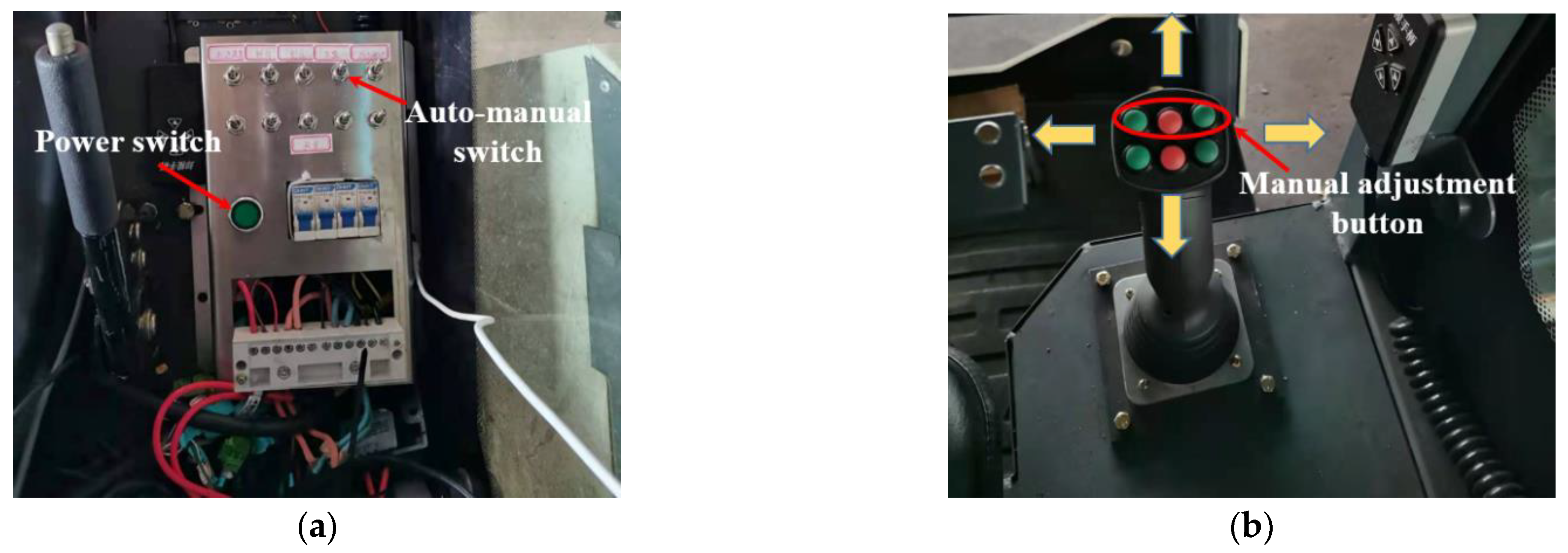
Leveling performance was tested under multiple conditions in Wujiang National Modern Agricultural Industrial Park (Suzhou, China) during December 2020. The CAN analysis recorder (Model: CANalyst-II, Chuangxin Technology Co., Ltd., Zhuhai, China) was used to record data, including vehicle inclination and displacement of hydraulic cylinders, saved as TXT file format. The controller was directly connected to the recorder, which can transmit four signals in a single experiment, and can realize horizontal leveling (two front hydraulic cylinder signals and Y-direction inclination signal) or the recording of related data in longitudinal leveling (two rear hydraulic cylinder signals and X-direction inclination signal).
The experiment started when the chassis was in the lowest level position, we manually adjusted the vehicle to the extreme left tilting state and then turned on the automatic leveling switch. Figure 13a shows the auto-leveling process, and Figure 13c shows the horizontal leveling test diagram. Within the first 1.5 s, the attitude sensor detected the vehicle’s inclination state, and the required adjustment displacement of the hydraulic cylinder was calculated. After measuring, control of the opening of the proportional valve where the corresponding hydraulic cylinder was located. Since the vehicle tilts to the left by the extension of the right front hydraulic cylinder, the extension of the hydraulic cylinder was at its maximum limit at 0 s, and the vehicle was tilted to the left by about 4.25°. Within 5 s, the front right hydraulic cylinder gradually contracted, and the lateral inclination angle of the vehicle body also gradually decreased. After about 6.5 s, the hydraulic cylinder contracted to the initial shortest state, at which time the vehicle remained horizontal.
When the chassis was in the lowest level position, we manually adjusted the body to any right tilt state, then turned on the automatic leveling switch. Figure 13b shows its automatic leveling process. After the automatic leveling was turned on, the control system detected the current vehicle inclination state through the attitude sensor and judged that the vehicle was tilted to the right by −2.20° at this moment. After the required adjustment of the hydraulic cylinder was obtained and the corresponding proportional valve was controlled to open, the vehicle body started to level after about 1.8 s. At 2.7 s, the left front hydraulic cylinder gradually shrunk, and the body gradually became horizontal. After about 4.4 s, the left front hydraulic cylinder retracted from the extended 33.8 mm to the initial position. At this time, the lateral tilt was −0.25°, and the body remained basically level.
After the whole chassis was raised about 40 mm, the longitudinal leveling test of the vehicle body was then carried out, as shown in Figure 14a for the longitudinal leveling process. First, we manually adjusted the body to the limit state of forward tilt, as shown in Figure 14b, and turned on the automatic leveling switch. At 1.8 s, the body started to level, and the rear hydraulic cylinder gradually shrunk from the extended 50 mm state. After 6.5 s, the hydraulic cylinder shrunk back to the initial position, and the longitudinal direction of the body remained basically horizontal. After an interval of about 10 s, we manually adjusted the body to any position of backward tilt and then turned on the automatic leveling switch. In order to facilitate the distinction of data, we turned on the automatic leveling switch after another interval of about 10 s. The control system detects that the vehicle tilted to the rear about 1.95° at this time, the hydraulic cylinder gradually extended 22.21 mm to the initial position within 2 s, and the vehicle was leveled longitudinally again.
From the above analysis, it can be seen that the designed crawler four-point lifting chassis structure can adjust its posture, realize the lateral and longitudinal adjustment of the vehicle body and each adjustment action is consistent with the theoretical analysis and simulation results. Since the engine power of the harvester is at the maximum in the leveling test, the body will vibrate to varying degrees, and the value detected by the attitude sensor will fluctuate in a very small range, but the leveling system can also accurately collect the tilt state of the body and realize the adjustment level. In addition, due to processing and assembly errors, clearance will exist between the hinged parts, but the accuracy of body leveling can be maintained within ±0.4°. Compared with the current leveling methods, the designed adaptive leveling system based on a four-point lifting adjustable crawler chassis can meet the leveling requirement of crawler agricultural machinery or engineering machinery.

5. Conclusions

A new adaptive leveling system for combine harvester has been developed on the basis of the proposed attitude adjustable crawler chassis, which could guarantee the vehicles and platforms in a level position when operated over rough terrain, and, therefore, able to adapt to multiple operating conditions. The attitude adjustment of the chassis depends on a four-point lifting adjustable mechanism, which could be conveniently applied to crawler vehicles to prevent rollover accidents and improve operational performance.
In this study, the working principle of the attitude adjustment mechanism has been analyzed based on the virtual prototype model in a RecurDyn environment. The adjustment process under different posture conditions has been simulated, and the results prove the feasibility of this method. In order to provide the adaptive leveling system with the calculation formulas for adjusting the displacement of hydraulic cylinders, the mathematical models between vehicle attitude and the working state of hydraulic cylinders have been established separately. From the analysis, the maximum adjustment range of vehicle height could be 0–87.8 mm, the lateral inclination adjustment range could be ±3.98° and the longitudinal inclination could be −2.9–5.2°.
The adaptive leveling experiment showed that the variation of real adjusting parameters was consistent with the simulation and theoretical analysis, including the hydraulic cylinder displacement and vehicle attitude. During the test conditions, the leveling system could achieve automatic leveling with an accuracy of ±0.4°. Therefore, the leveling method proposed in this article could be valuable for technical reference of crawler vehicle leveling.

Author Contributions

Conceptualization, J.H. and J.P.; methodology, J.H. and J.P.; validation, J.H., J.P. and Y.S.; investigation, B.D.; resources, B.D. and Y.S.; data curation, X.C. and L.X.; writing—original draft preparation, J.H. and J.P.; writing—review and editing, X.C. and L.X. All authors have read and agreed to the published version of the manuscript.

Funding

This research was funded by the National Natural Science Foundation of China, grant number 51875260, Taishan Industry Leading Talent Project, Leading Talents of National Ten Thousand Talents Program and Jiangsu Agriculture Science and Technology Innovation Fund (JASTIF), grant number CX((21)2042).

Institutional Review Board Statement

Not applicable.

Informed Consent Statement

Not applicable.

Data Availability Statement

The data presented in this study are available on request to the corresponding author.

Conflicts of Interest

The authors declare no conflict of interest.

References

  1. Chai, X.; Xu, L.; Li, Y.; Lv, L.; Zhu, Y. Development and experimental analysis of a grey fuzzy control system on rapeseed cleaning loss. Electronics 2020, 9, 1764. [Google Scholar] [CrossRef]
  2. Craessaerts, G.; Baerdemaeker, J.; Missotten, B. Fuzzy control of the cleaning process on a combine harvester. Biosyst. Eng. 2010, 106, 103–111. [Google Scholar] [CrossRef]
  3. Lou, Y. Study on the design of composite transmission system for crawler type full feeding combine harvester. Appl. Mech. Mater. 2014, 722, 80–83. [Google Scholar] [CrossRef]
  4. Xu, L.; Chai, X.; Gao, Z.; Li, Y.; Wang, Y. Experimental study on driver seat vibration characteristics of crawler-type combine harvester. Int. J. Agric. Biol. Eng. 2019, 12, 90–97. [Google Scholar] [CrossRef]
  5. Hiregoudar, S.; Udhaykumar, R.; Ramappa, K. Artificial neural network for assessment of grain losses for paddy combine harvester a novel approach. Control Comput. Inf. Syst. 2011, 140, 221–231. [Google Scholar] [CrossRef]
  6. Zhang, Z.; Noboru, N.; Kazunobu, I. Optimization of steering control parameters based on a combine harvester’s kinematic model. Eng. Agric. Environ. Food 2014, 7, 91–96. [Google Scholar] [CrossRef]
  7. Wang, Z.; Yang, J.; Liu, P. Development of an agricultural vehicle leveling system based on rapid active leveling. Biosyst. Eng. 2019, 186, 337–348. [Google Scholar] [CrossRef]
  8. Li, Y.; Zang, L.; Shi, T.; Lv, T.; Lin, F. Design and Dynamic Simulation Analysis of a Wheel–Track Composite Chassis Based on RecurDyn. World Electr. Veh. J. 2022, 13, 12. [Google Scholar] [CrossRef]
  9. Zemánek, T.; Neruda, J. Impact on the Operation of a Forwarder with the Wheeled, Tracked-Wheel or Tracked Chassis on the Soil Surface. Forests 2021, 12, 336. [Google Scholar] [CrossRef]
  10. Ahn, T.; Lee, Y.; Park, K. Design of Integrated Autonomous Driving Control System That Incorporates Chassis Controllers for Improving Path Tracking Performance and Vehicle Stability. Electronics 2021, 10, 144. [Google Scholar] [CrossRef]
  11. Li, Z.; Shi, Y.; Jiang, P.; Wu, H.; Lin, W. Design and experimental research of high clearance universal operation chassis. Food Mach. 2018, 34, 100–105. [Google Scholar]
  12. Zhang, Y.; Hu, Z.; Wang, B. Analysis of rice and wheat harvesting of hills and mountains in the southern. J. Agric. Mech. Res. 2012, 34, 246–248. [Google Scholar]
  13. Jin, C.; Yang, T.; Liu, G.; Wang, T.; Chen, M.; Liu, Z. Design and test of posture controlled chassis for caterpillar combine. Trans. Chin. Soc. Agric. Mach. 2020, 51, 400–409. [Google Scholar]
  14. Denis, D.; Thuilot, B.; Lenain, R. Online adaptive observer for rollover avoidance of reconfigurable agricultural vehicles. Comput. Electron. Agric. 2016, 126, 32–43. [Google Scholar] [CrossRef]
  15. Khorsandi, F.; Ayers, P.; Fong, E. Evaluation of crush protection devices for agricultural all-terrain vehicles. Biosyst. Eng. 2019, 185, 161–173. [Google Scholar] [CrossRef]
  16. Zhu, Q.; Wei, C.; Hu, H.; Wu, X.; Xiao, C.; Song, X. Multi-sensor based attitude prediction for agricultural vehicles. Comput. Electron. Agric. 2019, 156, 24–32. [Google Scholar] [CrossRef]
  17. Van Der Westhuizen, S.F.; Els, P.S. Slow active suspension control for rollover prevention. J. Terramech. 2013, 50, 29–36. [Google Scholar] [CrossRef] [Green Version]
  18. Sun, X.; Cai, Y.; Yuan, C. Fuzzy sliding mode control for the vehicle height and leveling adjustment system of an electronic air suspension. Chin. J. Mech. Eng. 2018, 31, 25. [Google Scholar] [CrossRef] [Green Version]
  19. Pan, D.; Jia, Y.; Yuan, B.; Liu, Y.; Dang, Z.; Lin, Y.; Wang, R.; Chen, M.; Wei, Q.; Zhao, Z.; et al. Design and verification of the active suspension mobility system of the Zhurong Mars rover. Sci. Sin. Technol. 2022, 52, 278–291. [Google Scholar] [CrossRef]
  20. Sun, J.; Meng, C.; Zhang, Y. Design and physical model experiment of an attitude adjustment device for a crawler tractor in hilly and mountainous regions. Inf. Process. Agric. 2020, 7, 466–478. [Google Scholar] [CrossRef]
  21. Edlund, J.; Keramati, E.; Servin, M. A long-tracked bogie design for forestry machines on soft and rough terrain. J. Terramech. 2013, 50, 73–83. [Google Scholar] [CrossRef]
  22. Liu, P.; Peng, F.; Li, H.; Wang, Z.; Wei, W.; Zhao, J. Design and experiment of adaptive leveling chassis for hilly area. Trans. Chin. Soc. Agric. Mach. 2017, 12, 5. [Google Scholar]
  23. Huang, Z. Talking about the promotion and use of harvesting machinery in hilly and mountainous areas. Chin. Agric. Mach. 2001, 3, 7–8. [Google Scholar]
  24. Liu, P.; Ke, C.; Ke, T.; Li, H.; Wei, W.; Zhao, C. Design and experiment of pre-detection active leveling agricultural chassis for hilly area. Trans. Chin. Soc. Agric. Mach. 2020, 3, 43. [Google Scholar] [CrossRef]
  25. Fendt C-Series SL. Available online: https://www.fendt.com/int/combines/c-series-sl-highlights (accessed on 8 February 2022).
  26. New Holland launches the CH7.70 Combine. Available online: https://www.plant-planet.co.uk/2020/07/25/new-holland-launches-the-ch7-70-combine/ (accessed on 8 February 2022).
  27. Zhou, C.; Huang, Y.; Ni, L. The dynamics simulation of tracked vehicles on the hard and soft ground based on the RecurDyn. Adv. Mater. Res. 2013, 842, 351–354. [Google Scholar] [CrossRef]
Figure 1. Schematic diagram of crawler combine harvester and welded integrated chassis. (1) header, (2) cab, (3) grain tank, (4) unloading device, (5) threshing device, (6) smashing device, (7) cleaning device.
Agronomy 12 00717 g001
Figure 2. Detailed structure of the attitude adjustment mechanism: (1) chassis frame, (2) right rear oscillating arm assembly, (3) right rear hydraulic cylinder, (4) right rear pivot arm, (5) right walking beam, (6) right front hydraulic cylinder, (7) left front hydraulic cylinder, (8) right connecting rod, (9) right front oscillating arm assembly, (10) right connecting arm, (11) driving wheel, (12) gearbox, (13) left front oscillating arm assembly, (14) left connecting arm, (15) left connecting rod, (16) left walking beam, (17) track roller, (18) left rear oscillating arm assembly, (19) left rear pivot arm, (20) left rear hydraulic cylinder, (21) thrust wheel, (22) tensioner.
Agronomy 12 00717 g002
Figure 3. Main working procedure of the adaptive leveling system.
Agronomy 12 00717 g003
Figure 4. Structure diagram of the control system.
Agronomy 12 00717 g004
Figure 5. Operation platform: (a) Auto-manual switch, (b) Control handle.
Agronomy 12 00717 g005
Figure 6. Longitudinal leveling posture range: E, F3 and R2 represent the maximum lifting height, maximum forward and maximum retroversion adjustment angles of the chassis, respectively; A, B, C and D represent 10%, 35%, 60% and 90% maximum lifting vehicle height, respectively; F1 and F2 represent 35% and 80% maximum forward angle, respectively; R1 represents 30% maximum forward angle.
Agronomy 12 00717 g006
Figure 7. Automatic posture leveling sequence. Y means yes; N means no.
Agronomy 12 00717 g007
Figure 8. Mathematical models of adjustment conditions. (a) Definition of inclination direction. (b) Overall lifting adjustment. (c) Lateral inclination leveling. (d) Longitudinal inclination leveling.
Agronomy 12 00717 g008
Figure 9. Simulation results of overall lifting adjustment and longitudinal tilting adjustment: (a) Forward inclination in the simulation environment. (b) Hydraulic cylinder displacement. (c) Displacement curve of the hinge point in the Y-direction. (d) Change curve of longitudinal inclination angle θ2. Position a: within 10–15 s, the chassis reached the horizontal position; Position b: within 15–20 s, the chassis reached the horizontal position again; Position c: at the 10 s, the chassis reached the maximum tilting adjustment angle −2.4°; Position d: at the 15 s, the chassis reached the maximum forward inclination adjustment 5.2°.
Agronomy 12 00717 g009
Figure 10. Simulation results of longitudinal tilting adjustment when the vehicle is in the lowest: (a) Displacement curve of the hinge point in the Y-direction. (b) Hydraulic cylinder displacement and lateral inclination θ2.
Agronomy 12 00717 g010
Figure 11. Simulation results of lateral tilting adjustment: (a) Left-leaning simulation diagram of chassis. (b) Hydraulic cylinder displacement and lateral inclination θ1.
Agronomy 12 00717 g011
Figure 12. The prototype with the adaptive leveling system.
Agronomy 12 00717 g012
Figure 13. Vehicle lateral leveling test of combine harvester. (a) Vehicle adaptive leveling after extreme left tilt. (b) Vehicle adaptive leveling after right tilt. (c) Vehicle lateral leveling test in the field.
Agronomy 12 00717 g013
Figure 14. Vehicle longitudinal leveling test of combine harvester. (a) Vehicle leveling after tilting longitudinally. (b) Vehicle longitudinal leveling test in the field.
Agronomy 12 00717 g014
Publisher’s Note: MDPI stays neutral with regard to jurisdictional claims in published maps and institutional affiliations.

