
Process Investigation on Robust Electrospinning of Non-Aligned and Aligned Polyvinylidene Fluoride Nanofiber Mats for Flexible Piezoelectric Sensors
Abstract
:1. Introduction
2. Fabrication of Pvdf Nanofiber Mats and Pressure Sensor
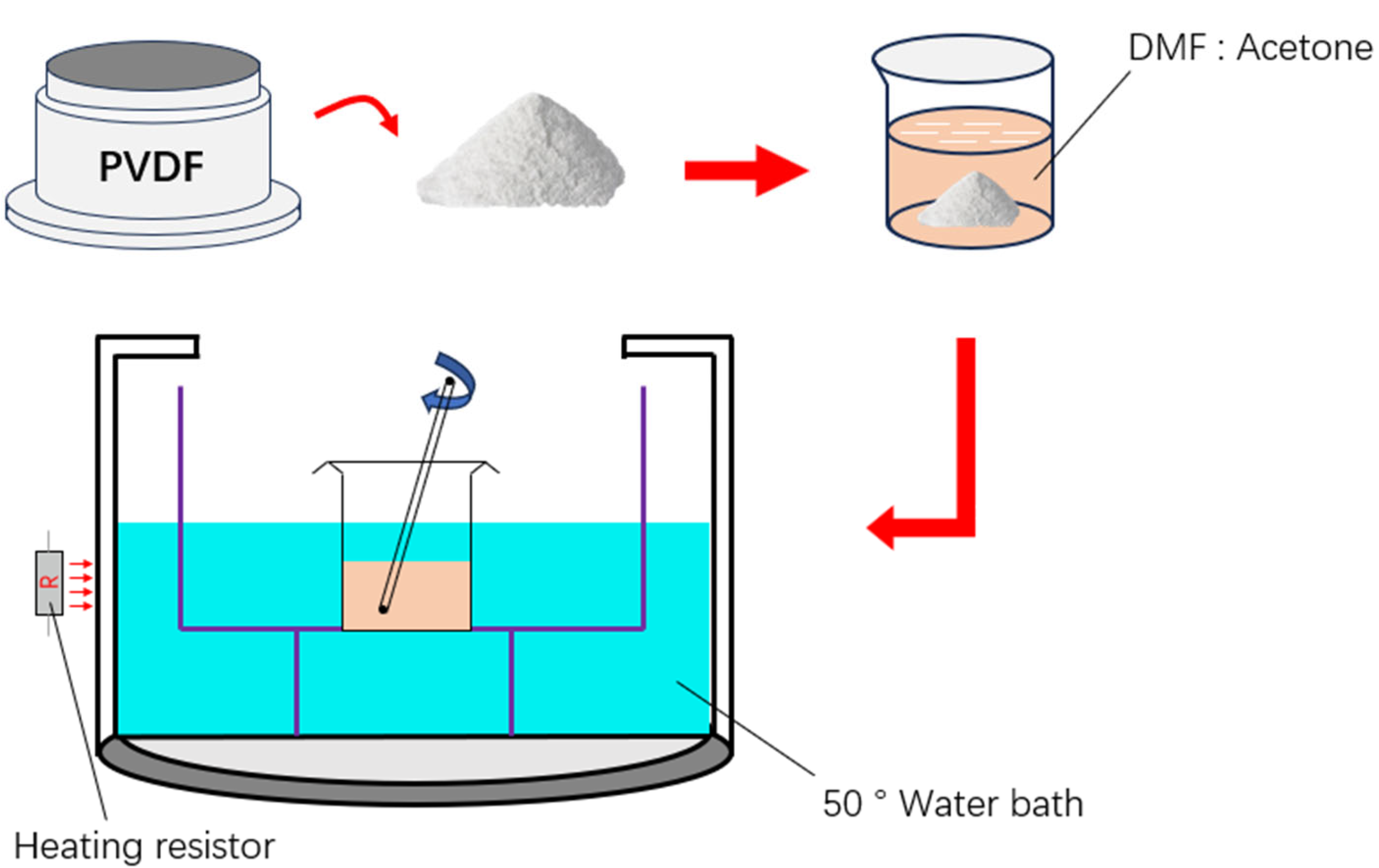
2.1. Material and Solvent Preparation
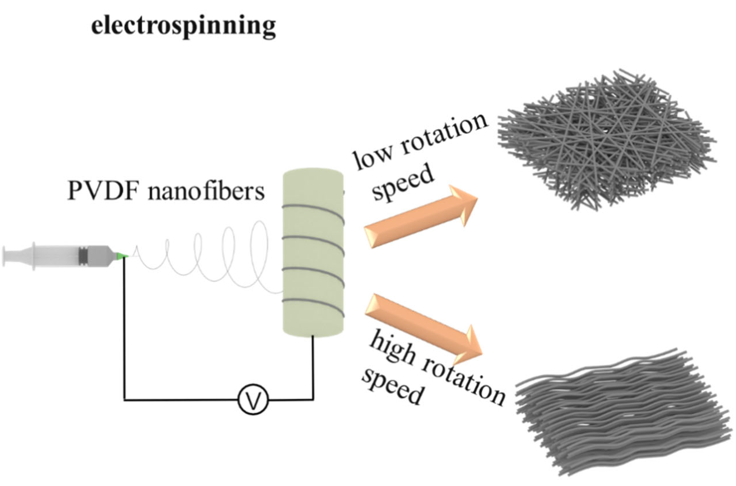
2.2. Electrospinning Process under Different Conditions
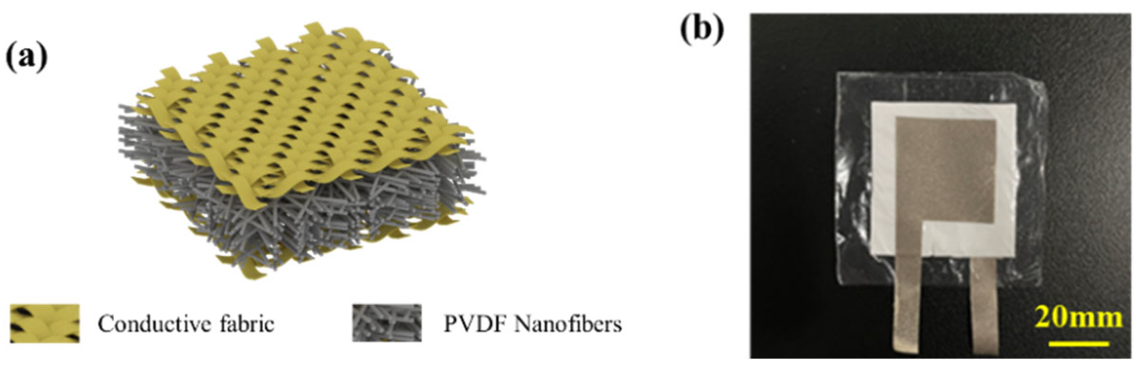
2.3. Electronic Skin Pressure Sensor Assembly
2.4. Characterization and Measurement
3. Results and Discussion
3.1. Effect of Processing Parameters on Morphology and Performance of Nanofibers
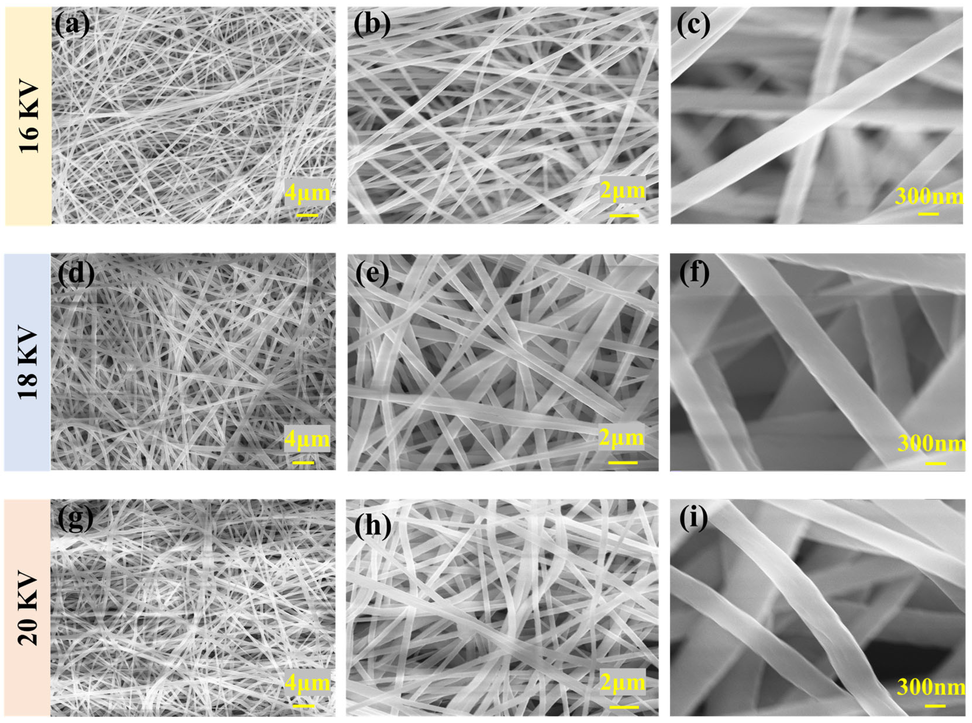
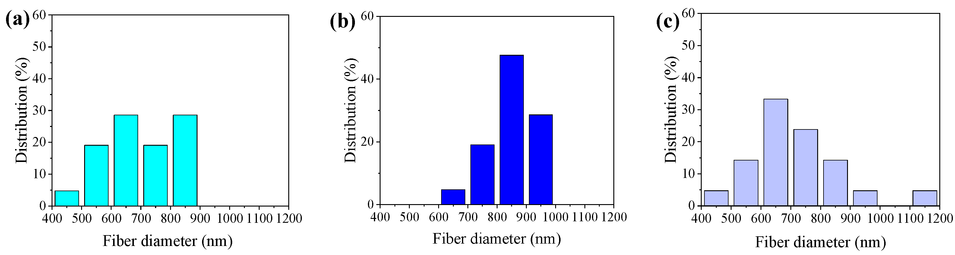
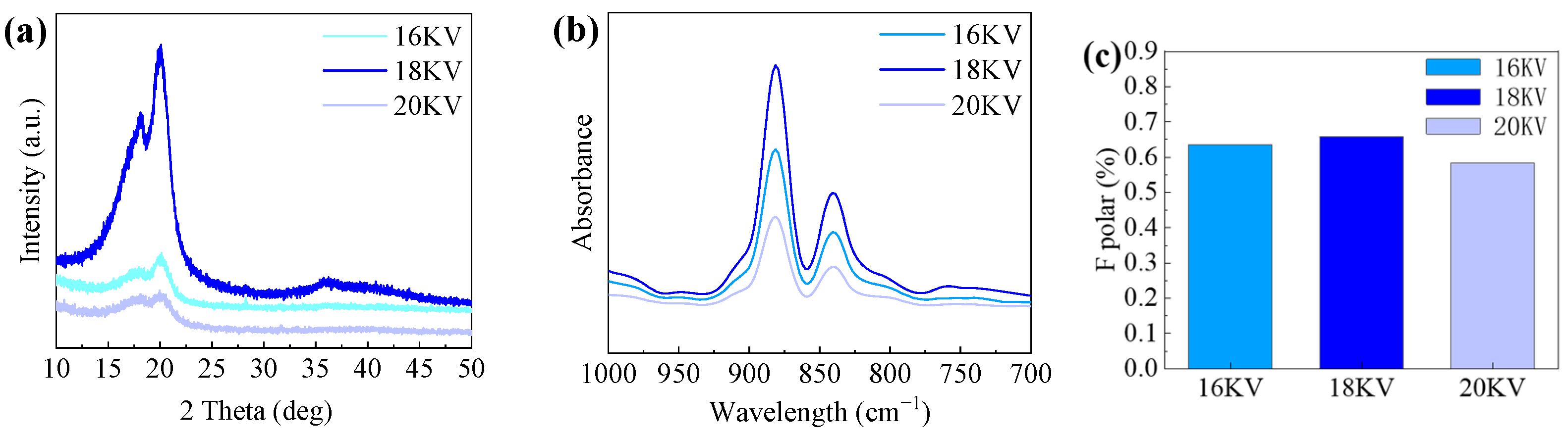
3.1.1. Voltage
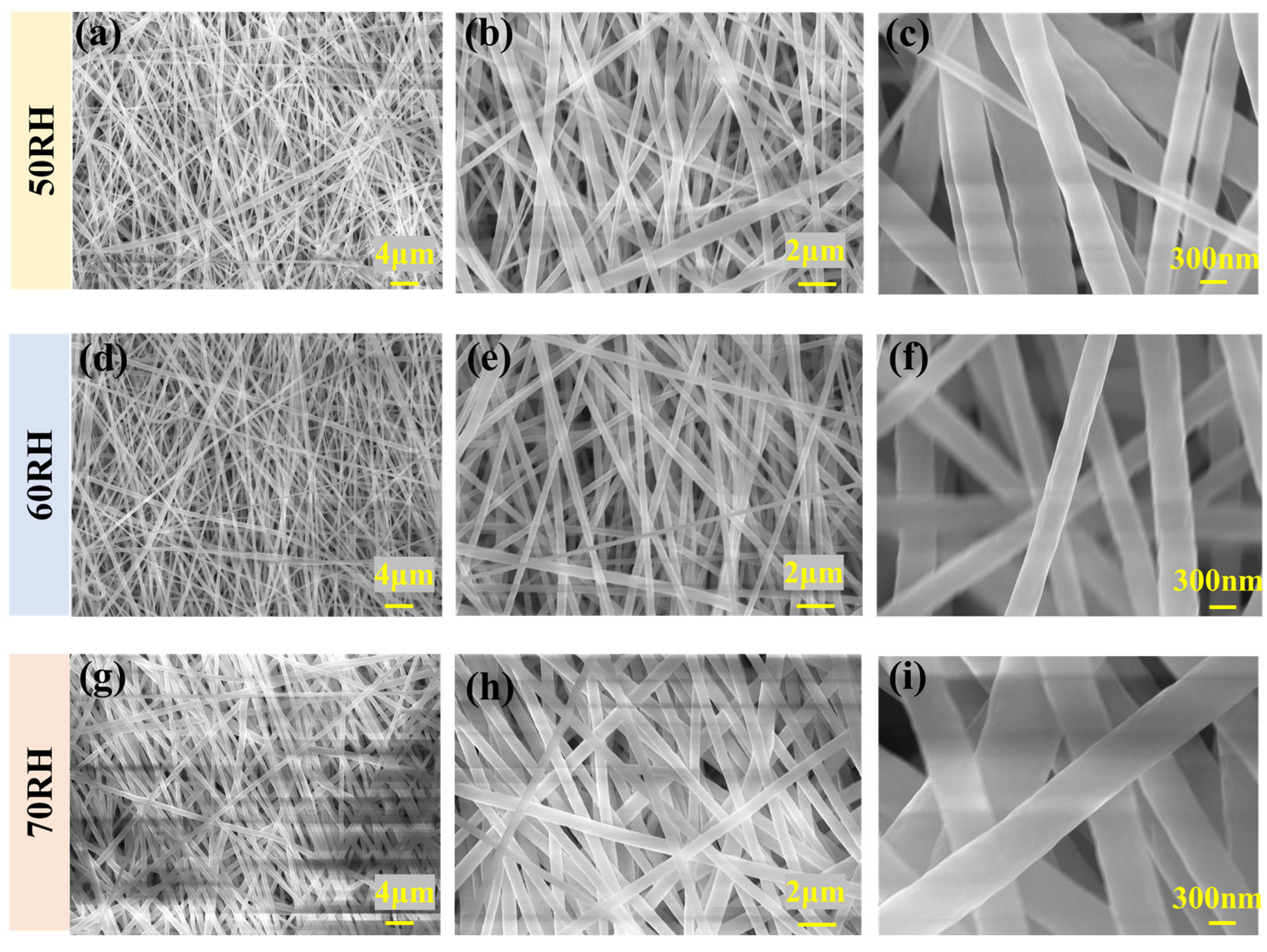
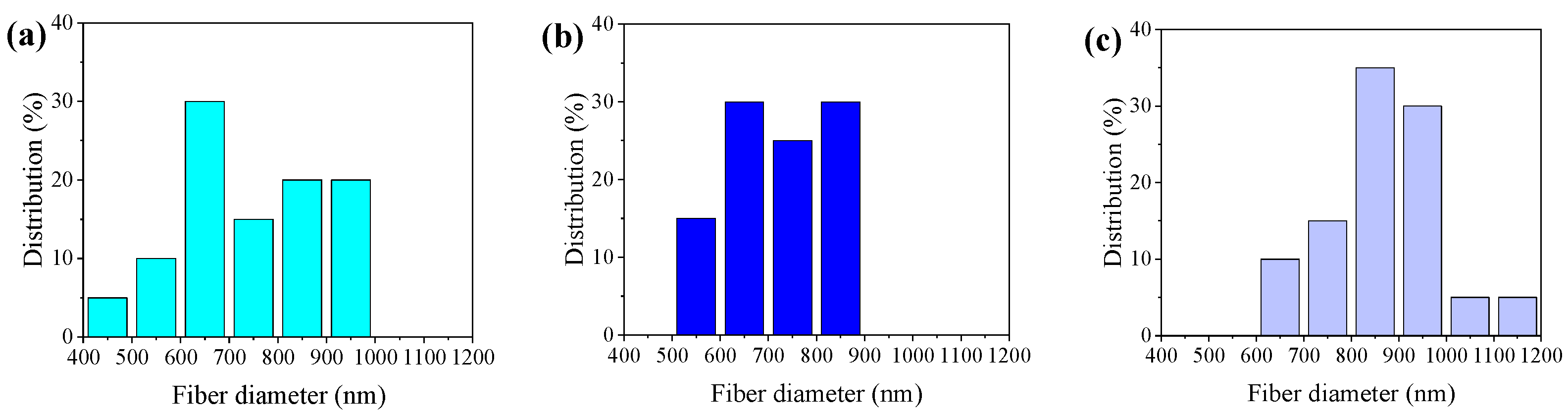
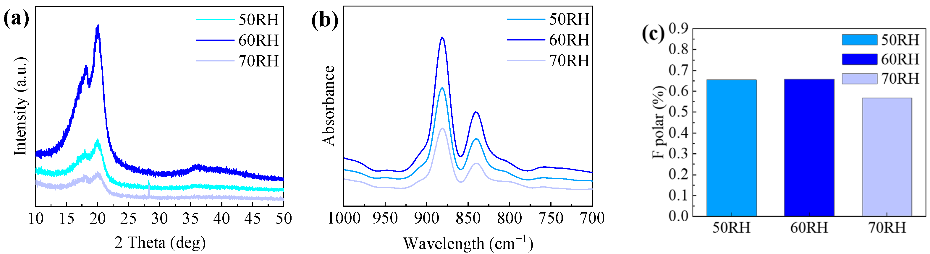
3.1.2. Humidity
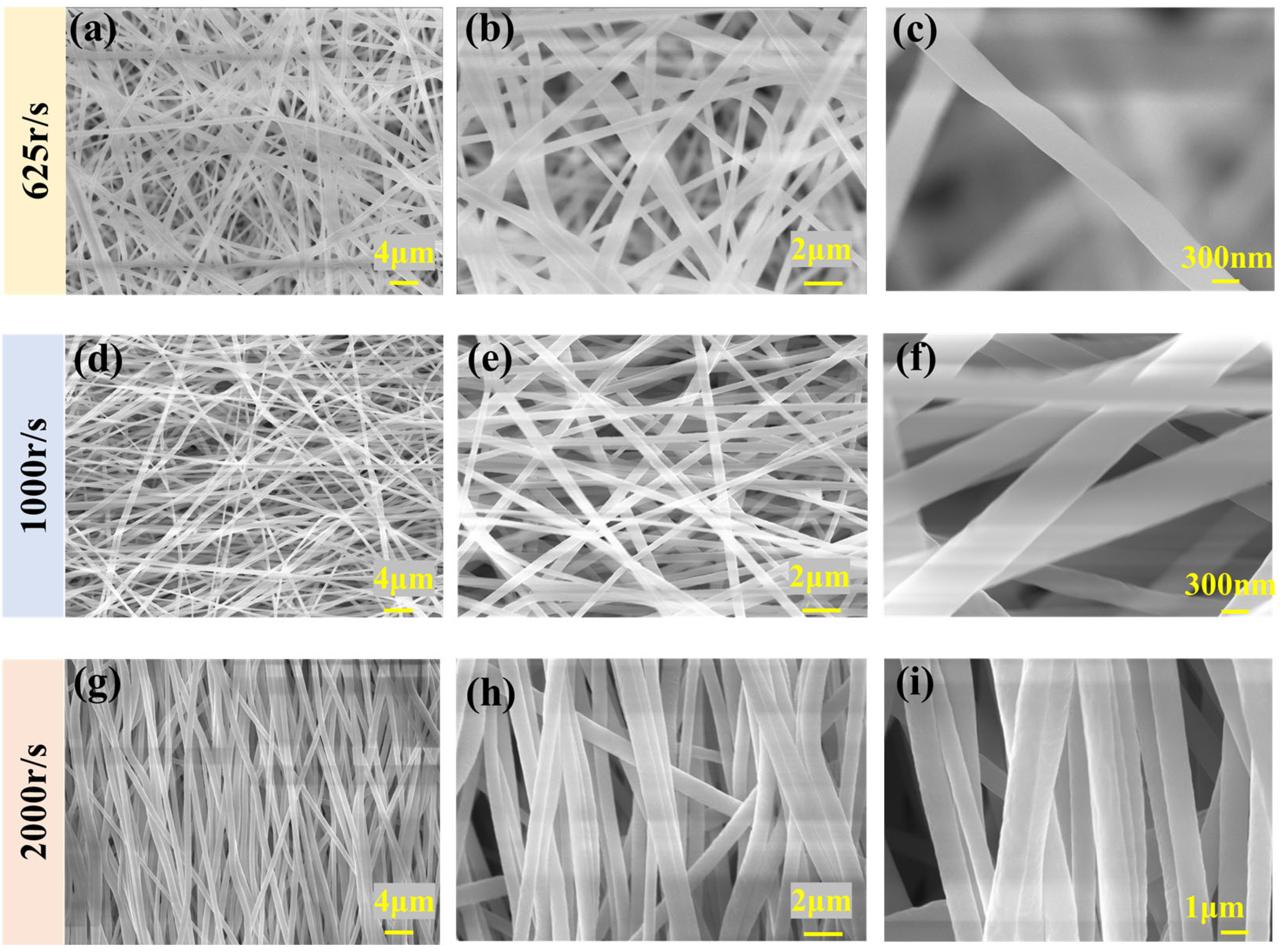
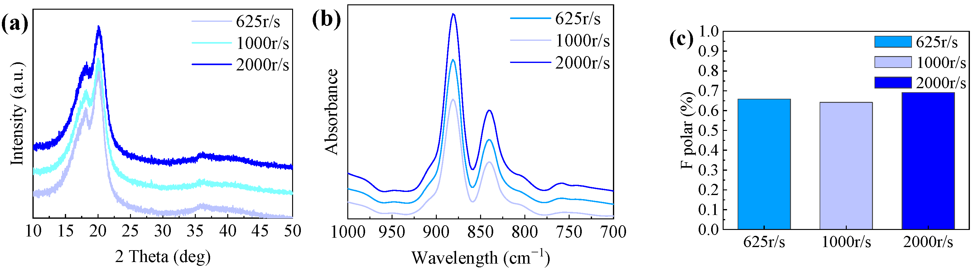
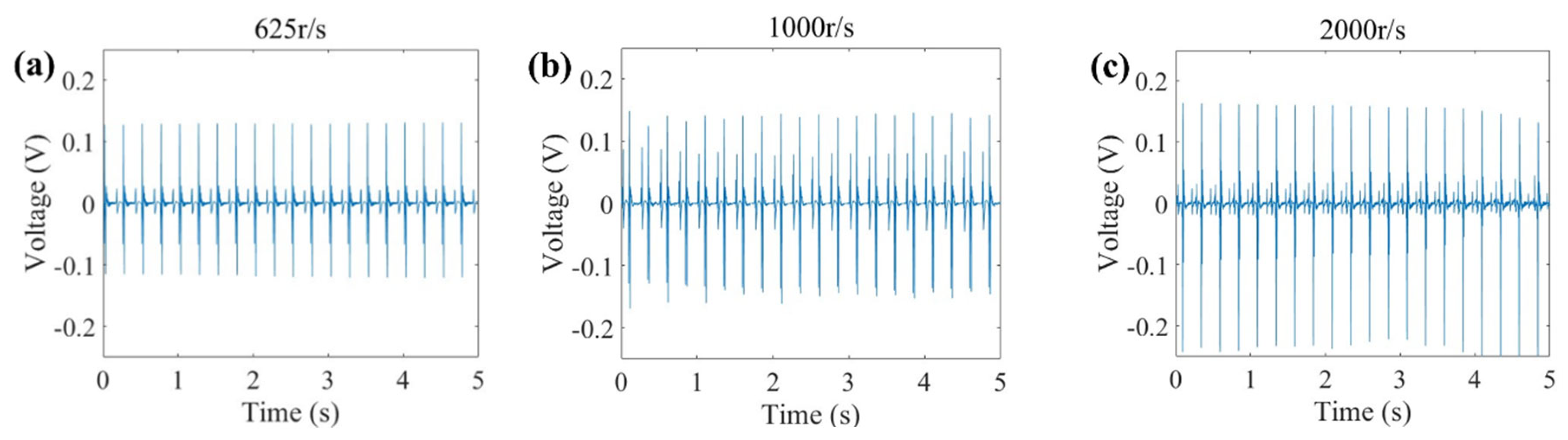
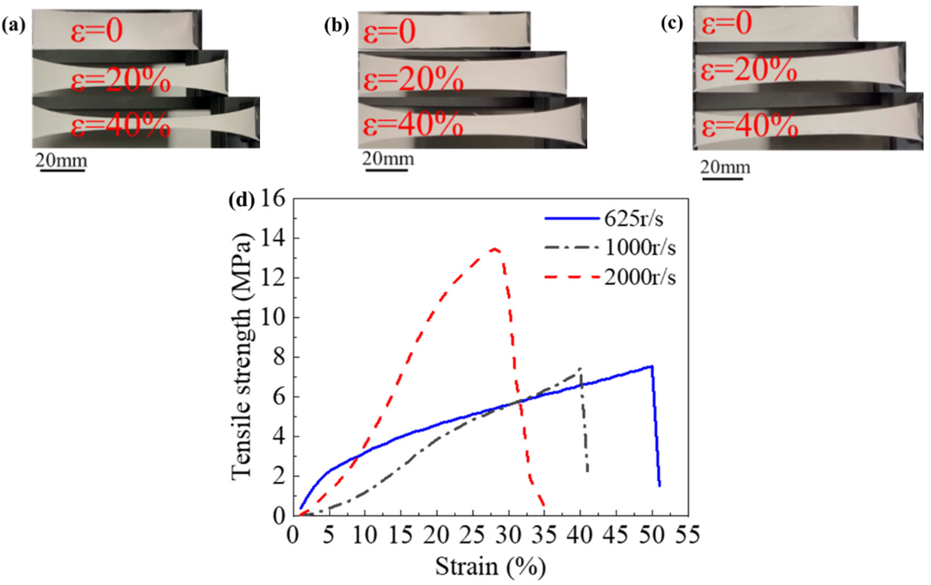
3.1.3. Drum Speed
3.2. Electronic Skin Pressure Sensor Unit Performance Test
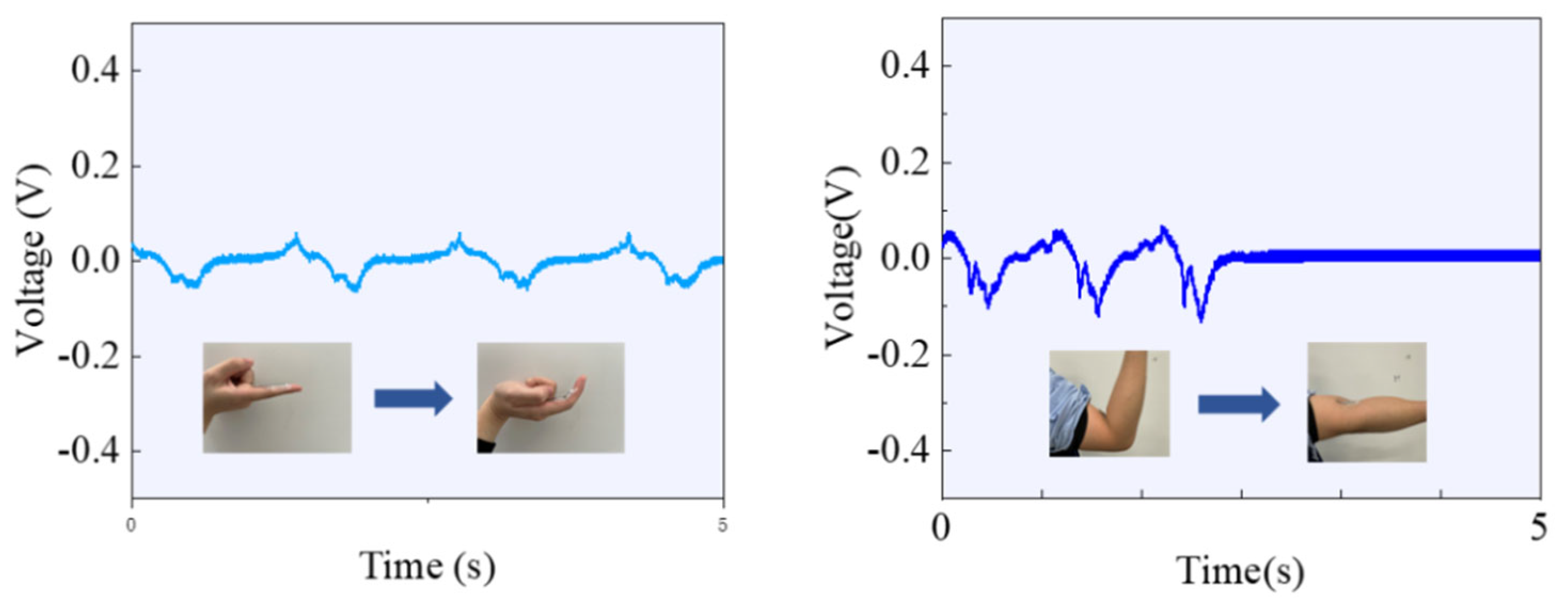
3.3. Human Joint Movement Characterization by Flexible Sensors
4. Conclusions
- (1)
- Both the uniformity of fiber diameter and the content of the β phase can be maintained within a favorable range when the voltage is 18 kV and the humidity is 60% RH. Building upon this foundation, the fibers exhibited significant orientation, and the content of the β phase showed a noticeable increase when the drum rotation speed reached 2000 r/s.
- (2)
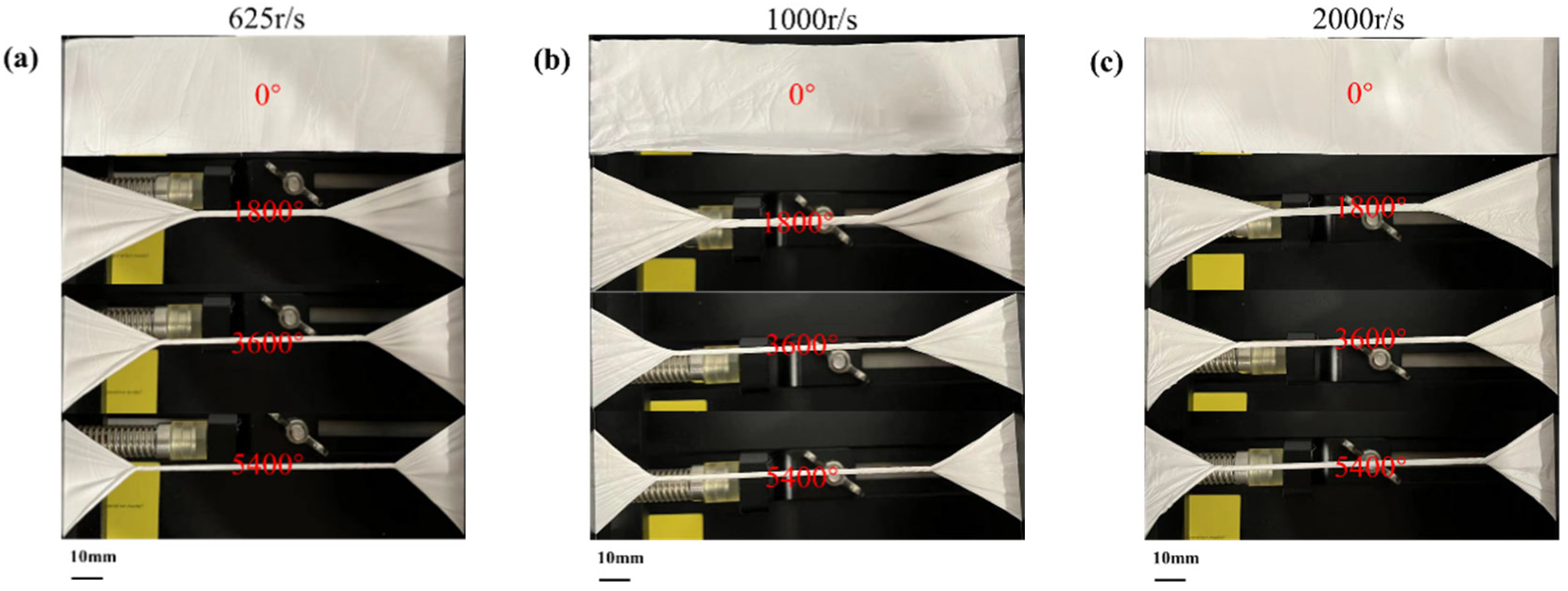
- Higher drum rotation speed leads to aligned piezoelectric nanofibers, which exhibit higher electrical and mechanical output performance compared to non-aligned piezoelectric fibers.
- (3)
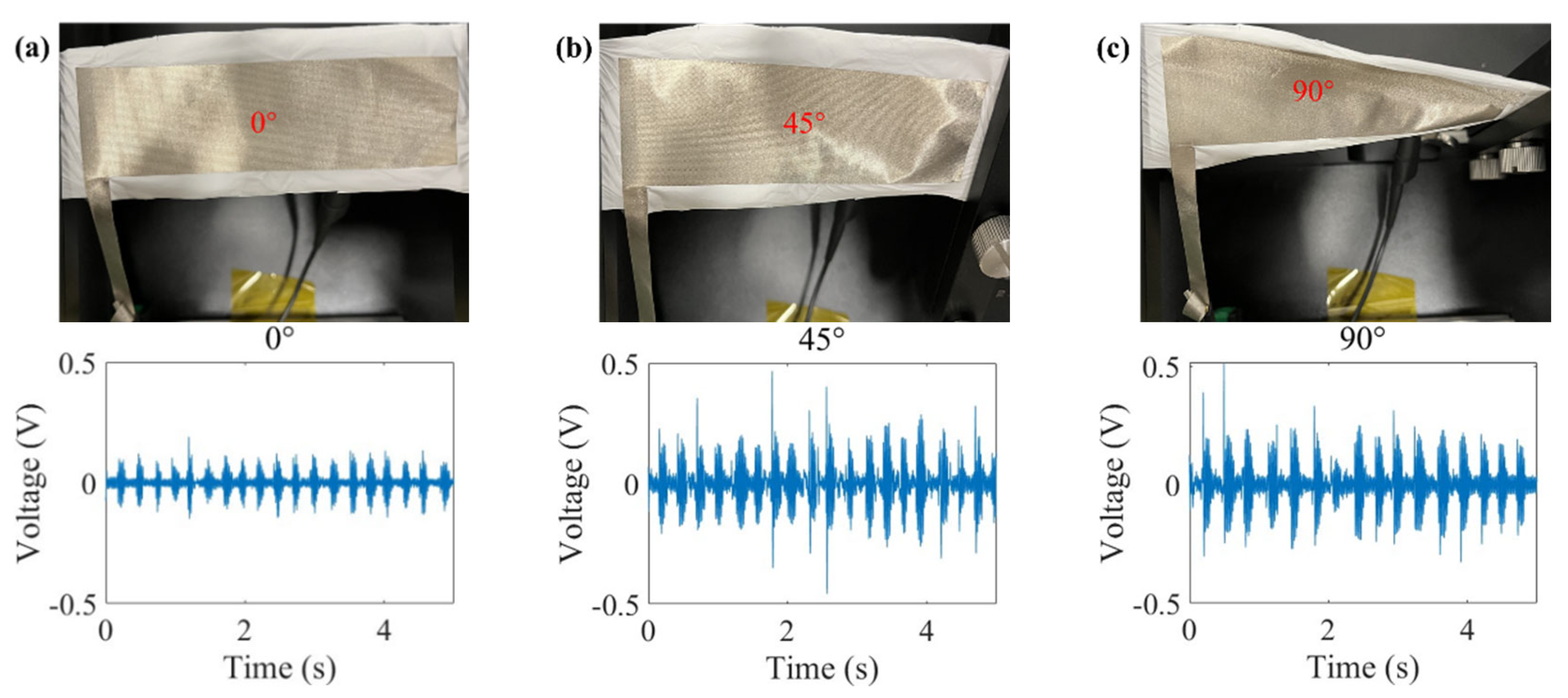
- The wearable flexible sensor can maintain good electrical output at a distortion angle of 0–90° and has good torsional resistance.
- (4)
- The prepared wearable flexible sensor exhibits high shape adaptability without compromising its sensing capabilities. Simultaneously, its self-powered functionality eliminates the need for rigid batteries, allowing it to conform well to curved surfaces such as joints for sensing.
Author Contributions
Funding
Institutional Review Board Statement
Data Availability Statement
Conflicts of Interest
References
- Li, Z.; Zhu, M.; Shen, J.; Qiu, Q.; Yu, J.; Ding, B. All-fiber structured electronic skin with high elasticity and breathability. Adv. Funct. Mater. 2020, 30, 1908411. [Google Scholar] [CrossRef]
- Zhang, D.; Zhang, X.; Li, X.; Wang, H.; Sang, X.; Zhu, G.; Yeung, Y. Enhanced piezoelectric performance of PVDF/BiCl3/ZnO nanofiber-based piezoelectric nanogenerator. Eur. Polym. J. 2022, 166, 110956. [Google Scholar] [CrossRef]
- Guo, H.; Wan, J.; Wu, H.; Wang, H.; Miao, L.; Song, Y.; Chen, H.; Han, M.; Zhang, H. Self-Powered Multifunctional Electronic Skin for a Smart Anti-Counterfeiting Signature System. ACS Appl. Mater. Interfaces 2020, 12, 22357–22364. [Google Scholar] [CrossRef]
- Yang, T.; Deng, W.; Chu, X.; Wang, X.; Hu, Y.; Fan, X.; Song, J.; Gao, Y.; Zhang, B.; Tian, G. Hierarchically microstruc-ture-bioinspired flexible piezoresistive bioelectronics. ACS Nano 2021, 15, 11555–11563. [Google Scholar] [CrossRef]
- Pan, C.-T.; Chang, C.-C.; Yang, Y.-S.; Yen, C.-K.; Kao, Y.-H.; Shiue, Y.-L. Development of MMG sensors using PVDF piezoelectric electrospinning for lower limb rehabilitation exoskeleton. Sens. Actuators A Phys. 2020, 301, 111708. [Google Scholar] [CrossRef]
- Leng, L.B.; Giin, L.B.; Chung, W.-Y. Wearable Driver Drowsiness Detection System Based on Biomedical and Motion Sensors, Busan, Korea, 1–4 November 2015; IEEE: Piscataway, NJ, USA, 2015; pp. 1–4. [CrossRef]
- Kalani, S.; Kohandani, R.; Bagherzadeh, R. Flexible electrospun PVDF–BaTiO3 hybrid structure pressure sensor with enhanced efficiency. RSC Adv. 2020, 10, 35090–35098. [Google Scholar] [CrossRef]
- Zhu, M.; Lou, M.; Abdalla, I.; Yu, J.; Li, Z.; Ding, B. Highly shape adaptive fiber based electronic skin for sensitive joint motion monitoring and tactile sensing. Nano Energy 2020, 69, 104429. [Google Scholar] [CrossRef]
- He, Z.; Rault, F.; Lewandowski, M.; Mohsenzadeh, E.; Salaün, F. Electrospun PVDF Nanofibers for Piezoelectric Applications: A Review of the Influence of Electrospinning Parameters on the β Phase and Crystallinity Enhancement. Polymers 2021, 13, 174. [Google Scholar] [CrossRef]
- Xue, J.; Wu, T.; Dai, Y.; Xia, Y. Electrospinning and electrospun nanofibers: Methods, materials, and applications. Chem. Rev. 2019, 119, 5298–5415. [Google Scholar] [CrossRef]
- Fan, F.R.; Tang, W.; Wang, Z.L. Flexible Nanogenerators for Energy Harvesting and Self-Powered Electronics. Adv. Mater. 2016, 28, 4283–4305. [Google Scholar] [CrossRef]
- Joseph, J.; Kumar, M.; Tripathy, S.; Kumar, G.D.V.S.; Singh, S.G.; Vaniari, S.R.K. A Highly Flexible Tactile Sensor with Self-Poled Electrospun PVDF Nanofiber, New Delhi, India, 28–31 October 2018; IEEE: Piscataway, NJ, USA, 2018; pp. 1–4. [CrossRef]
- Liu, Z.; Li, G.; Qin, Q.; Mi, L.; Li, G.; Zheng, G.; Liu, C.; Li, Q.; Liu, X. Electrospun PVDF/PAN membrane for pressure sensor and sodium-ion battery separator. Adv. Compos. Hybrid Mater. 2021, 4, 1215–1225. [Google Scholar] [CrossRef]
- Dong, W.; Xiao, L.; Hu, W.; Zhu, C.; Huang, Y.; Yin, Z. Wearable human–machine interface based on PVDF piezoelectric sensor. Trans. Inst. Meas. Control 2017, 39, 398–403. [Google Scholar] [CrossRef]
- Li, Q.; Xing, J.; Shang, D.; Wang, Y. A Flow Velocity Measurement Method Based on a PVDF Piezoelectric Sensor. Sensors 2019, 19, 1657. [Google Scholar] [CrossRef]
- Maity, K.; Garain, S.; Henkel, K.; Schmeißer, D.; Mandal, D. Self-Powered Human-Health Monitoring through Aligned PVDF Nanofibers Interfaced Skin-Interactive Piezoelectric Sensor. ACS Appl. Polym. Mater. 2020, 2, 862–878. [Google Scholar] [CrossRef]
- Xin, Y.; Qi, X.; Tian, H.; Guo, C.; Li, X.; Lin, J.; Wang, C. Full-fiber piezoelectric sensor by straight PVDF/nanoclay nanofibers. Mater. Lett. 2016, 164, 136–139. [Google Scholar] [CrossRef]
- Andrew, J.S.; Clarke, D.R. Effect of Electrospinning on the Ferroelectric Phase Content of Polyvinylidene Difluoride Fibers. Langmuir 2008, 24, 670–672. [Google Scholar] [CrossRef]
- Mokhtari, F.; Shamshirsaz, M.; Latifi, M. Investigation of β phase formation in piezoelectric response of electro-spun polyvinylidene fluoride nanofibers: LiCl additive and increasing fibers tension. Polym. Eng. Sci. 2016, 56, 61–70. [Google Scholar] [CrossRef]
- Diani, J.; Liu, Y.; Gall, K. Finite strain 3D thermoviscoelastic constitutive model for shape memory polymers. Polym. Eng. Sci. 2006, 46, 486–492. [Google Scholar] [CrossRef]
- Hansen, B.J.; Liu, Y.; Yang, R.; Wang, Z.L. Hybrid Nanogenerator for Concurrently Harvesting Biomechanical and Biochemical Energy. ACS Nano 2010, 4, 3647–3652. [Google Scholar] [CrossRef] [PubMed]
- Kang, D.H.; Kang, H.W. Advanced electrospinning using circle electrodes for freestanding PVDF nanofiber film fabrication. Appl. Surf. Sci. 2018, 455, 251–257. [Google Scholar] [CrossRef]
- Varposhti, A.M.; Yousefzadeh, M.; Kowsari, E.; Latifi, M. Enhancement of β-Phase Crystalline Structure and Piezoelectric Properties of Flexible PVDF/Ionic Liquid Surfactant Composite Nanofibers for Potential Application in Sensing and Self-Powering. Macromol. Mater. Eng. 2020, 305, 1900796. [Google Scholar] [CrossRef]
- Mokhtari, F.; Shamshirsaz, M.; Latifi, M.; Asadi, S. Comparative evaluation of piezoelectric response of electrospun PVDF (polyvinilydine fluoride) nanofiber with various additives for energy scavenging application. J. Text. Inst. 2017, 108, 906–914. [Google Scholar] [CrossRef]
- Yousry, Y.M.; Yao, K.; Mohamed, A.M.; Liew, W.H.; Chen, S.; Ramakrishna, S. Theoretical Model and Outstanding Performance from Constructive Piezoelectric and Triboelectric Mechanism in Electrospun PVDF Fiber Film. Adv. Funct. Mater. 2020, 30, 1910592. [Google Scholar] [CrossRef]
- Persano, L.; Dagdeviren, C.; Su, Y.; Zhang, Y.; Girardo, S.; Pisignano, D.; Huang, Y.; Rogers, J.A. High performance piezoelectric devices based on aligned arrays of nanofibers of poly(vinylidenefluoride-co-trifluoroethylene). Nat. Commun. 2013, 4, 1633. [Google Scholar] [CrossRef]
- Zaarour, B.; Zhu, L.; Huang, C.; Jin, X. Enhanced piezoelectric properties of randomly oriented and aligned elec-trospun PVDF fibers by regulating the surface morphology. J. Appl. Polym. Sci. 2019, 136, 47049. [Google Scholar] [CrossRef]
- Kabir, E.; Khatun, M.; Nasrin, L.; Raihan, M.J.; Rahman, M. Pure β-phase formation in polyvinylidene fluoride (PVDF)-carbon nanotube composites. J. Phys. D Appl. Phys. 2017, 50, 163002. [Google Scholar] [CrossRef]
- Guo, Y.; Zhang, H.; Zhong, Y.; Shi, S.; Wang, Z.; Wang, P.; Zhao, Y. Triboelectric Nanogenerator-Based Near-Field Electrospinning System for Optimizing PVDF Fibers with High Piezoelectric Performance. ACS Appl. Mater. Interfaces 2023, 15, 5242–5252. [Google Scholar] [CrossRef] [PubMed]
- Ueberschlag, P. PVDF piezoelectric polymer. Sens. Rev. 2001, 21, 118–126. [Google Scholar] [CrossRef]
- Kalimuldina, G.; Turdakyn, N.; Abay, I.; Medeubayev, A.; Nurpeissova, A.; Adair, D.; Bakenov, Z. A review of piezo-electric PVDF film by electrospinning and its applications. Sensors 2020, 20, 5214. [Google Scholar] [CrossRef] [PubMed]


| Voltage | Humidity | Drum Speed | Deposition Rate | |||
|---|---|---|---|---|---|---|
| Voltage control group | Set value | Mean | Variance | 625 r/s | 0.36 cm3/h | |
| 16 KV | 50 RH | 49.98 RH | 1.06 | |||
| 18 KV | 50 RH | 49.58 RH | 1.36 | |||
| 20 KV | 50 RH | 50.01 RH | 1.09 | |||
| Humid control group | 18 KV | Set value | Mean | Variance | 625 r/s | 0.36 cm3/h |
| 50 RH | 50.04 RH | 1.14 | ||||
| 60 RH | 59.51 RH | 1.09 | ||||
| 70 RH | 69.93 RH | 0.80 | ||||
| Rotation speed control group | 18 KV | Set value | Mean | Variance | 0.36 cm3/h | |
| 60 RH | 59.51 RH | 1.09 | 625 r/s | |||
| 60 RH | 59.56 RH | 1.11 | 1000 r/s | |||
| 60 RH | 59.58 RH | 0.99 | 2000 r/s | |||
| Voltage | Average (μm) | Variance |
|---|---|---|
| 16 KV | 0.689 | 0.0151 |
| 18 KV | 0.847 | 0.007 |
| 20 KV | 0.709 | 0.0278 |
| Humidity | Average (μm) | Variance |
|---|---|---|
| 50 RH | 0.743 | 0.0230 |
| 60 RH | 0.718 | 0.0114 |
| 70 RH | 0.875 | 0.0142 |
Disclaimer/Publisher’s Note: The statements, opinions and data contained in all publications are solely those of the individual author(s) and contributor(s) and not of MDPI and/or the editor(s). MDPI and/or the editor(s) disclaim responsibility for any injury to people or property resulting from any ideas, methods, instructions or products referred to in the content. |
© 2024 by the authors. Licensee MDPI, Basel, Switzerland. This article is an open access article distributed under the terms and conditions of the Creative Commons Attribution (CC BY) license (https://creativecommons.org/licenses/by/4.0/).
Share and Cite
Liu, X.; Zhang, M.; Jiang, B.; Zhang, Q.; Chen, H.; Shen, Y.; Wang, Z.; Yin, X. Process Investigation on Robust Electrospinning of Non-Aligned and Aligned Polyvinylidene Fluoride Nanofiber Mats for Flexible Piezoelectric Sensors. Polymers 2024, 16, 816. https://doi.org/10.3390/polym16060816
Liu X, Zhang M, Jiang B, Zhang Q, Chen H, Shen Y, Wang Z, Yin X. Process Investigation on Robust Electrospinning of Non-Aligned and Aligned Polyvinylidene Fluoride Nanofiber Mats for Flexible Piezoelectric Sensors. Polymers. 2024; 16(6):816. https://doi.org/10.3390/polym16060816
Chicago/Turabian StyleLiu, Xiaohua, Minghai Zhang, Baolin Jiang, Qihao Zhang, Hao Chen, Yan Shen, Ziyan Wang, and Xiaohong Yin. 2024. "Process Investigation on Robust Electrospinning of Non-Aligned and Aligned Polyvinylidene Fluoride Nanofiber Mats for Flexible Piezoelectric Sensors" Polymers 16, no. 6: 816. https://doi.org/10.3390/polym16060816