
Investigation of the Influence of Fiber Content, Processing Conditions and Surface Roughness on the Polymer Filling Behavior in Thermoset Injection Molding

Abstract
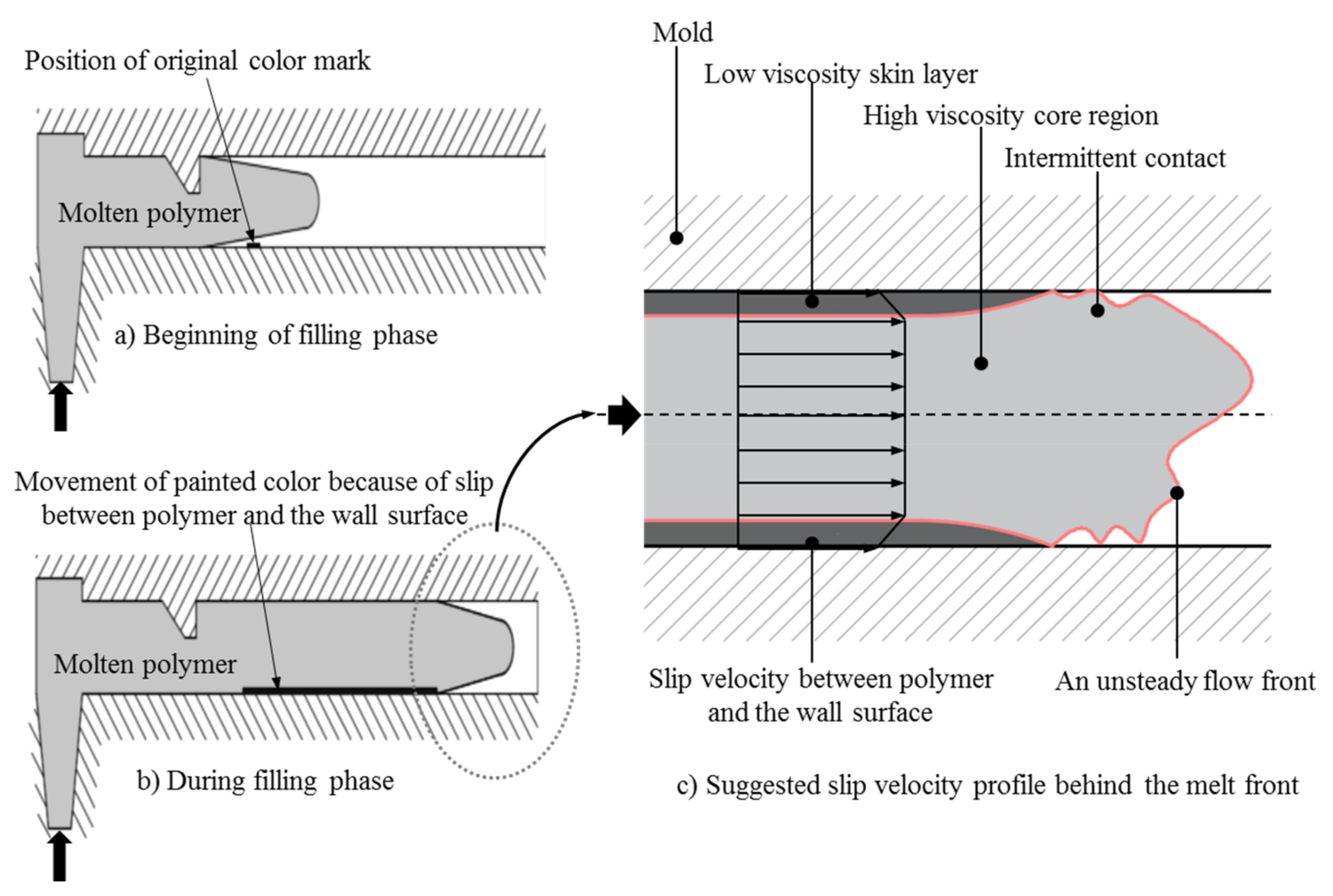
:1. Introduction
2. Materials and Methods
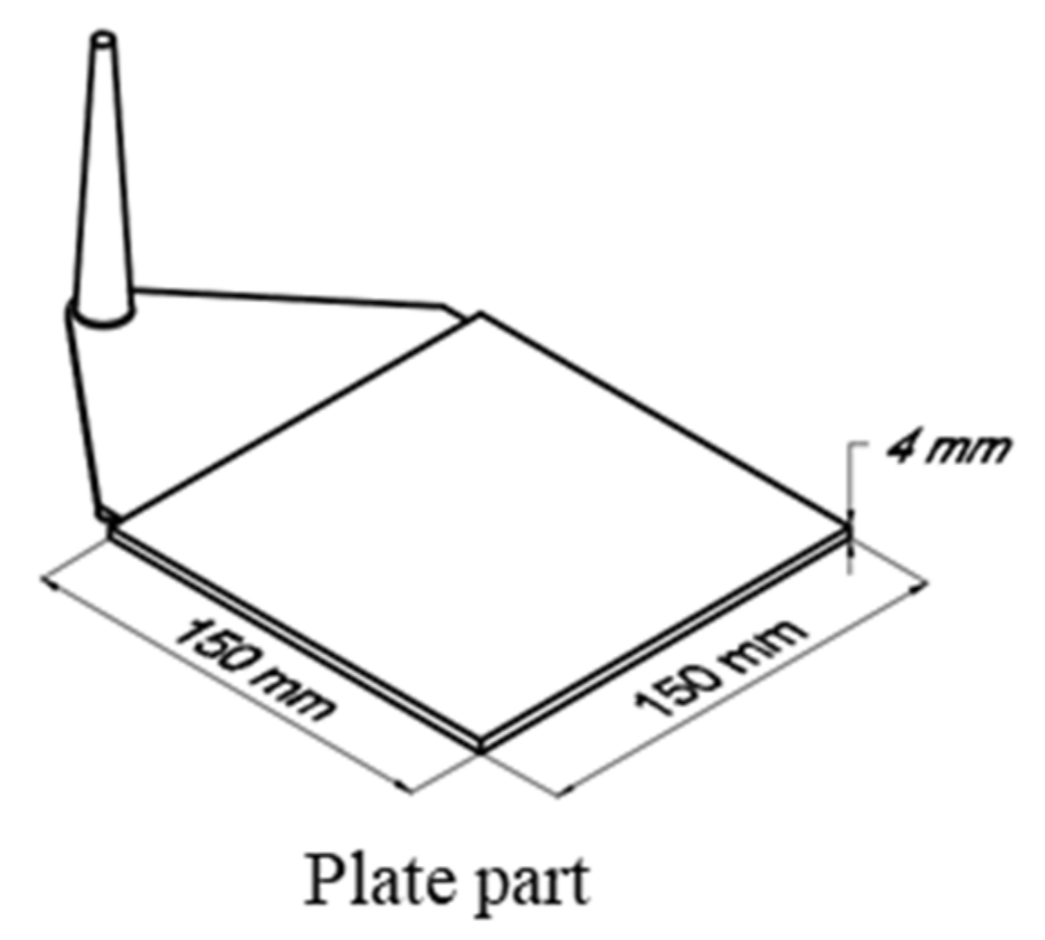
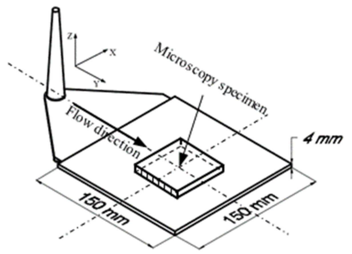
2.1. Material and Equipment
2.2. Experimental Procedure
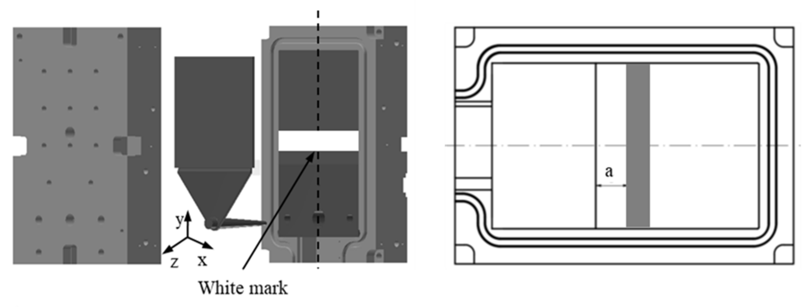
2.2.1. Investigation of the Influence of Filler Content on Slip Phenomenon
2.2.2. Investigation of the Influence of Injection Speed and Mold Temperature on Slip Phenomenon
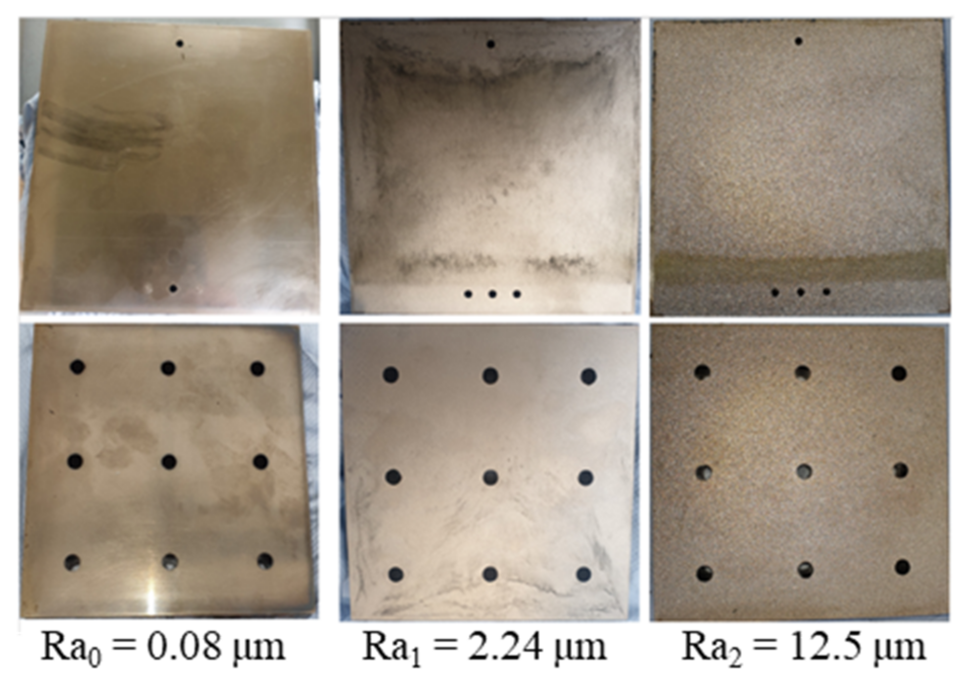
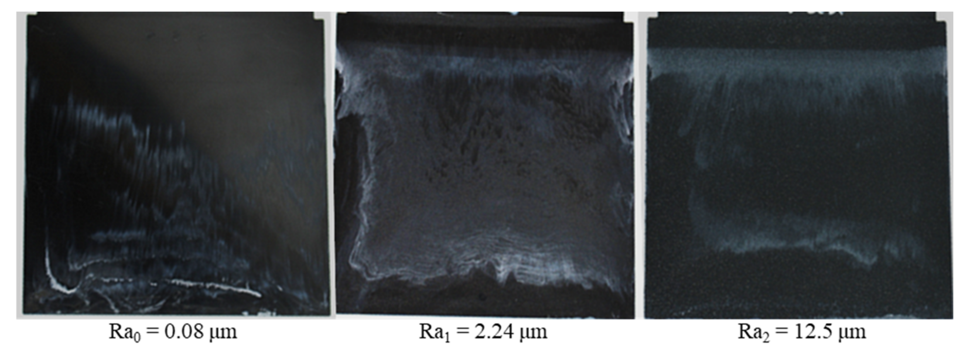
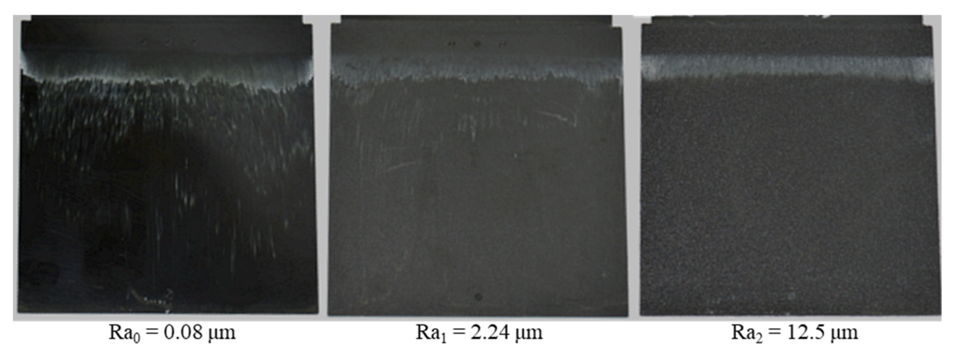
2.2.3. Investigation of the Influence of Surface Roughness on Slip Phenomenon
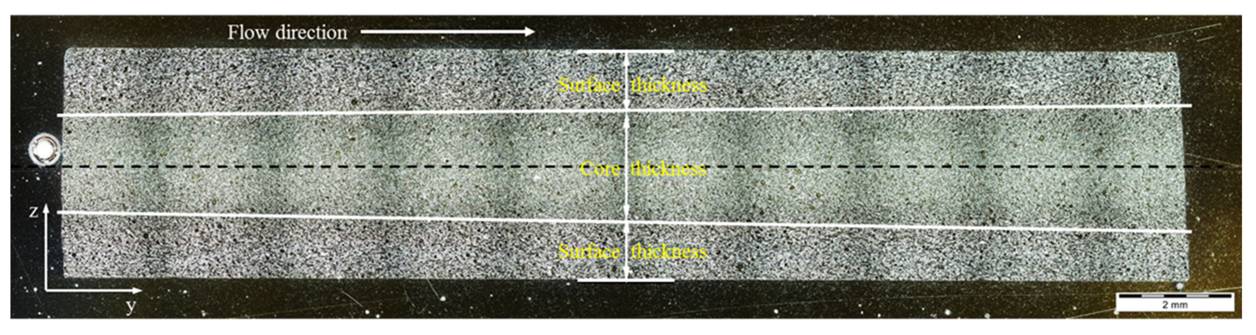
2.2.4. Investigation of Slip Phenomenon on the Fiber Orientation
3. Results and Discussion
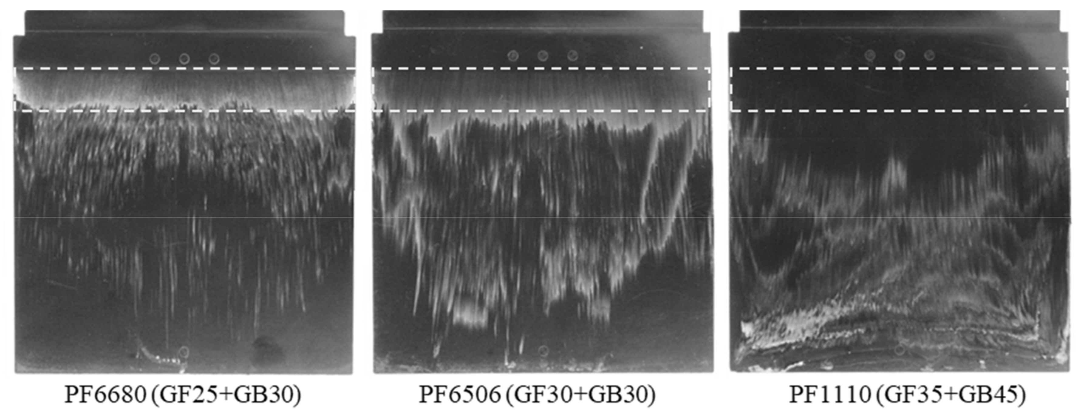
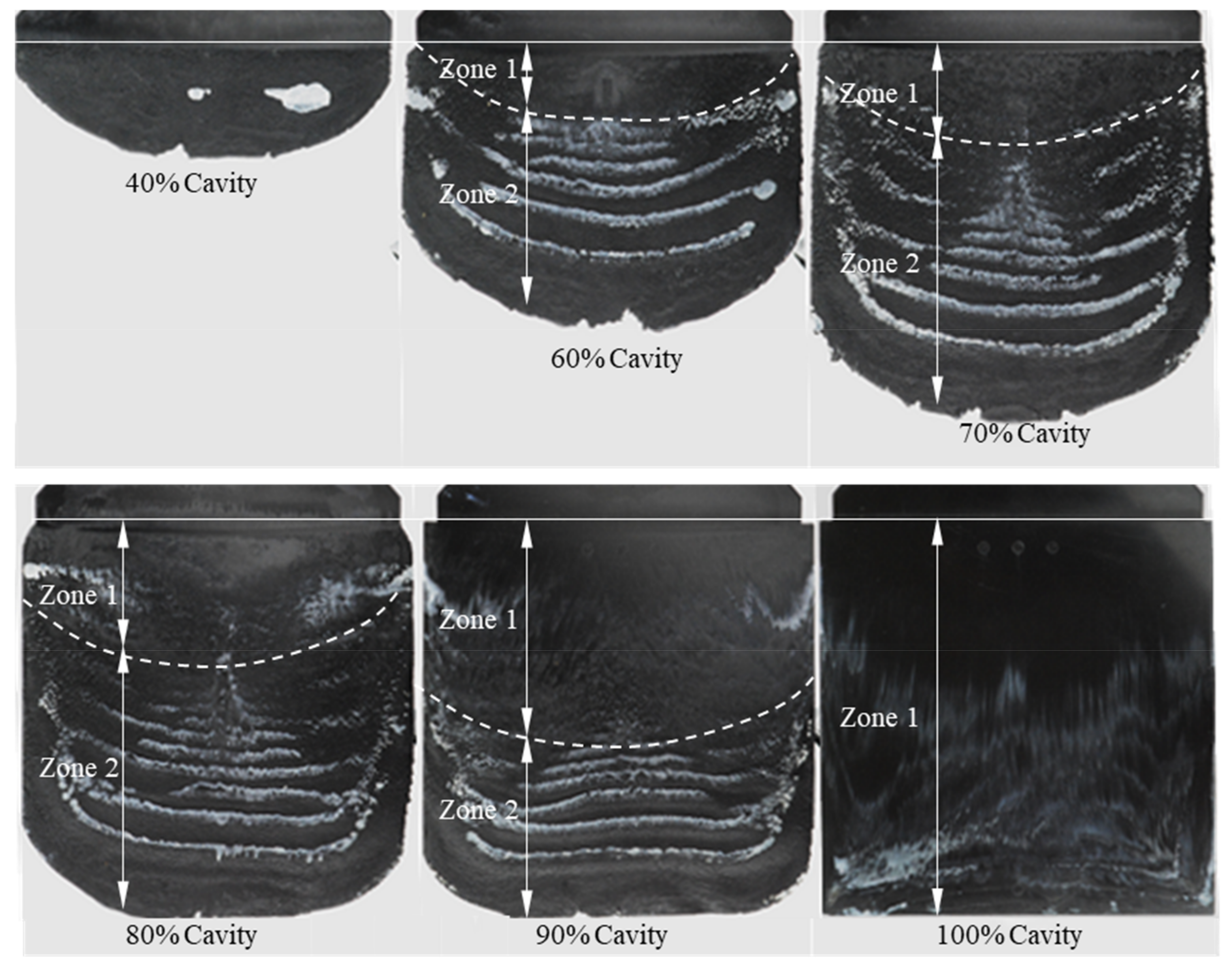
3.1. Influence of Filler Content on Slip Phenomenon of Highly Filled Thermoset Molding Compounds
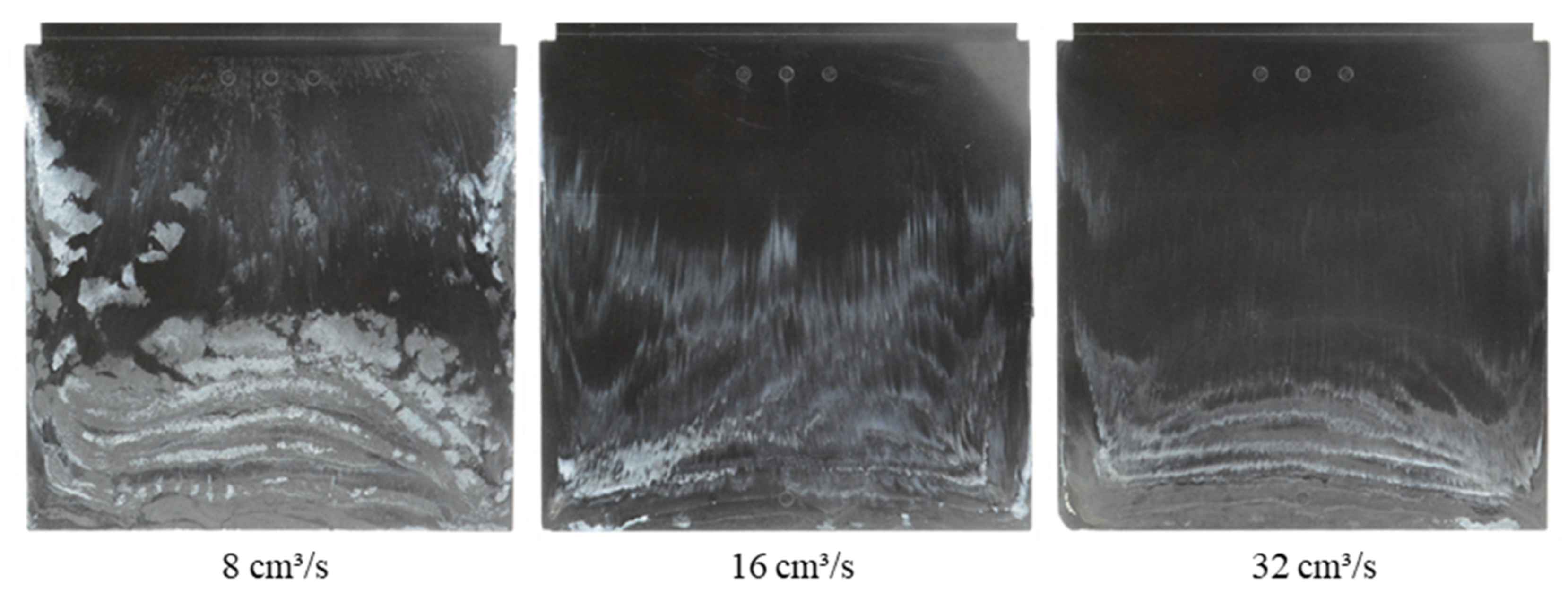
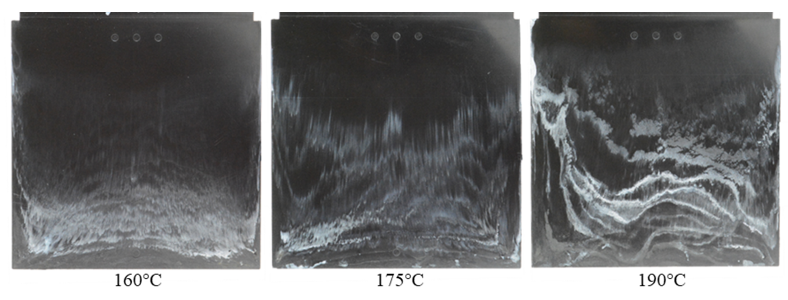
3.2. Influence of Injection Speed and Mold Temperature on Slip Phenomenon
3.3. Influence of Surface Roughness on Slip Phenomenon
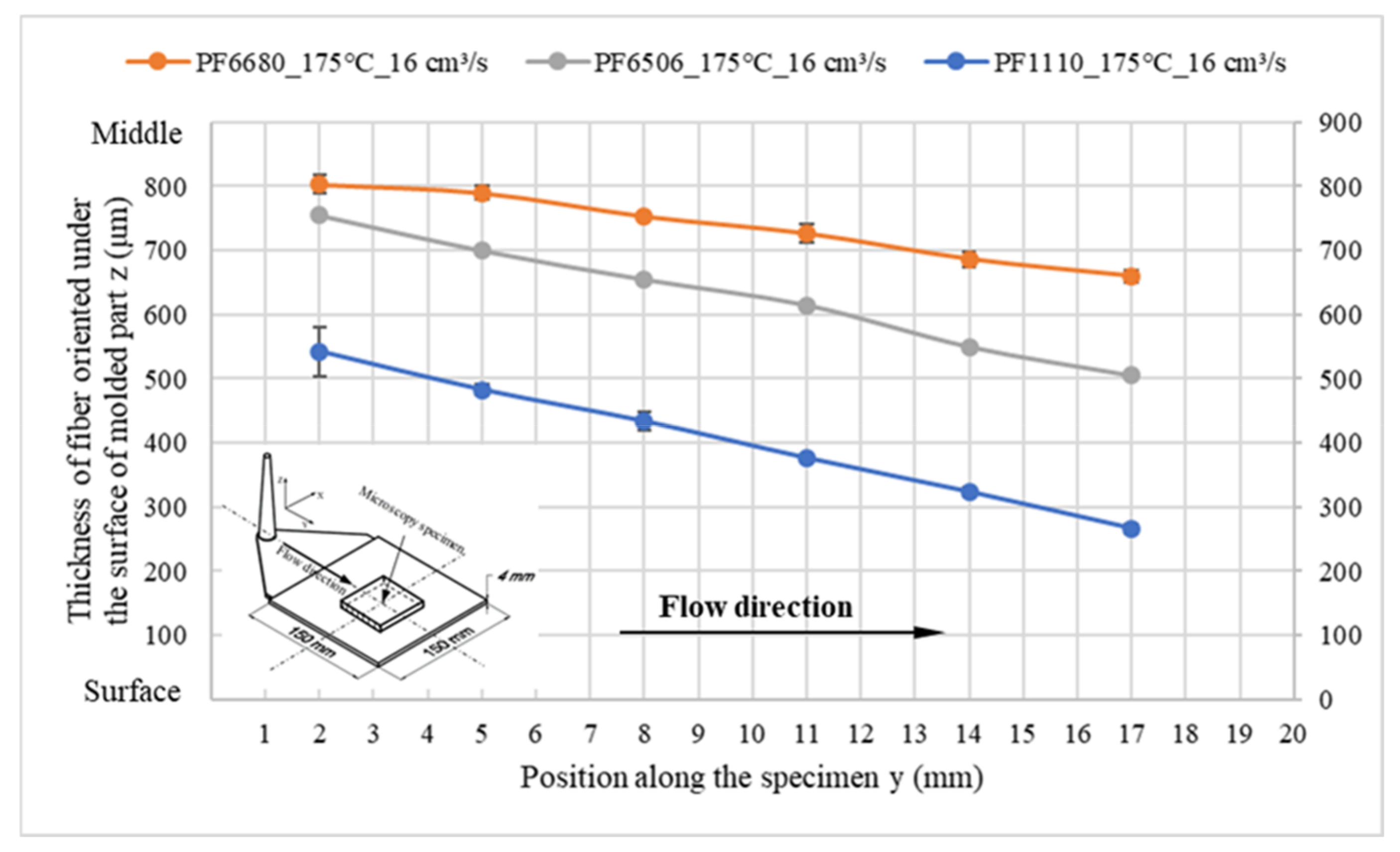
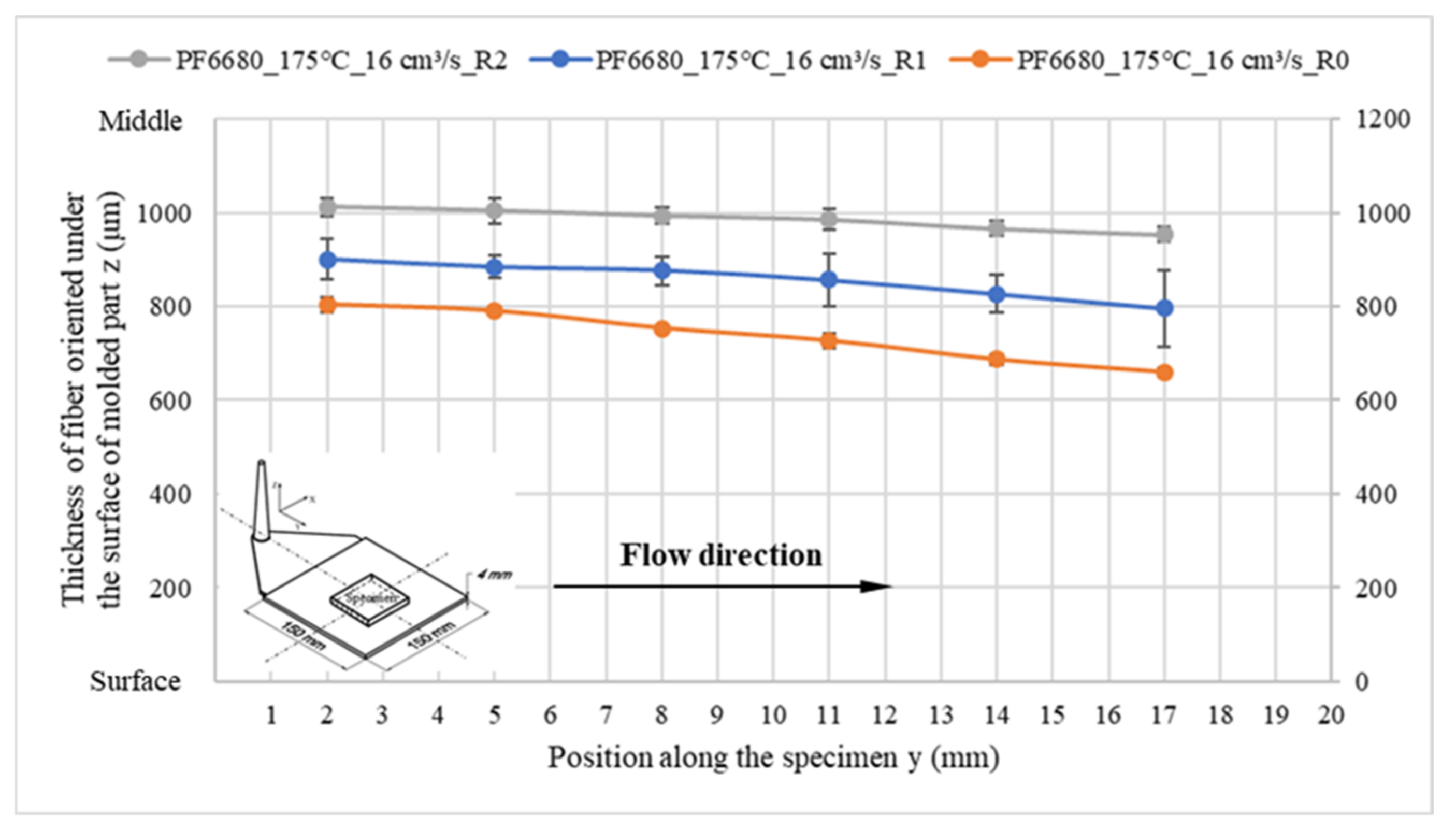
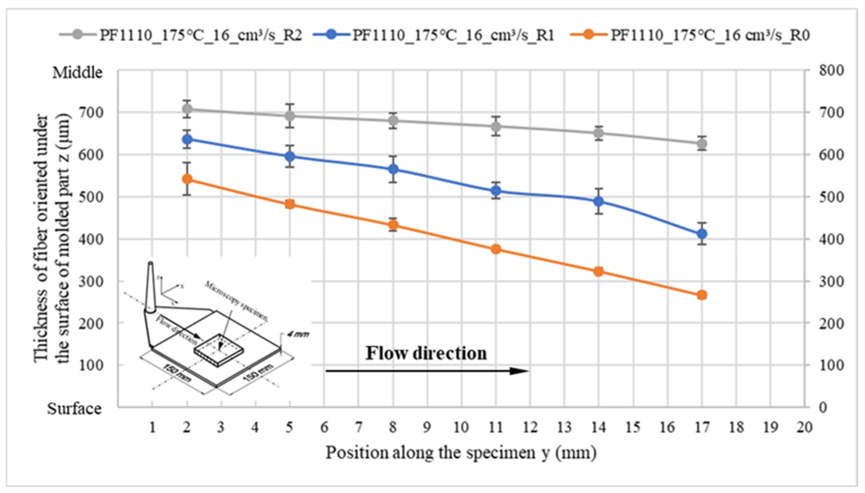
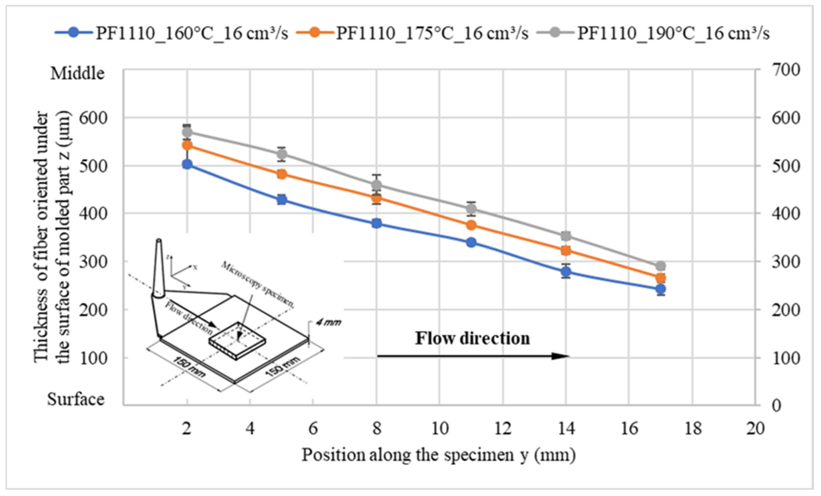
3.4. Influence of Slip Phenomenon on the Fiber Orientation
4. Conclusions
Author Contributions
Funding
Data Availability Statement
Acknowledgments
Conflicts of Interest
References
- Wieland, C.; Topic, N.; Hirz, J. More precision for sensitive fast curing compounds. Kunststoffe 2018, 8, 20–23. [Google Scholar]
- Osswald, T.A.; Menges, G. Materials Science of Polymers for Engineering; Carl Hanser: Munich, Germany, 2003. [Google Scholar]
- Haagh, G.A.A.V.; Peters, G.W.M.; Meijer, H.E.H. Reaction injection molding: Analyzing the filling stage of a complex product with highly viscous thermoset. Polym. Eng. Sci. 1996, 36, 2579–2588. [Google Scholar] [CrossRef] [Green Version]
- Michaeli, W. Plastics Processing: An Introduction; Carl Hanser: Munich, Germany, 1995. [Google Scholar]
- Singh, R.; Chen, F.; Jones, F.R. Injection moulding of glass fiber reinforced phenolic composites 2: Study of the injection molding process. Polym. Compos. 1998, 19, 37–47. [Google Scholar] [CrossRef]
- Buschhaus, F. Automatisierung beim Spritzgießen von Duroplasten und Elastomeren. Ph.D. Thesis, RWTH Aachen University, Aachen, Germany, 1982. [Google Scholar]
- Fischbach, M. Prozessführung beim Spritzgießen Härtbarer Formmassen. Ph.D. Thesis, RWTH Aachen University, Aachen, Germany, 1982. [Google Scholar]
- Bronke, D. Herstellung von duroplastischen Präzisionsteilen. Plastverarbeiter 1985, 36, 24–25. [Google Scholar]
- Macosko, C.W. RIM, Fundamentals of Reaction Injection Molding; Hanser Publishers: New York, NY, USA, 1989. [Google Scholar]
- Hunold, D. Analyse der Verarbeitungseigenschaften Duromerer Formmassen und Ansätze zur Prozessoptimierung beim Spritzgießen. Ph.D. Thesis, RWTH Aachen University, Aachen, Germany, 1992. [Google Scholar]
- Lee, L.J. Modelling and computer simulation of reactive processing. Compr. Polym. Sci. Suppl. 1989, 17, 575–617. [Google Scholar]
- Thienel, P.; Hoster, B.; Schröder, T.; Schröder, K.; Kretzschner, J. Duroplast-Spritzgießen mit Gasinnendruck. Kunststoffe 1993, 83, 91–94. [Google Scholar]
- Ohta, T. Visual analysis of cavity filling and packing process in injection molding of thermoset phenolic resin by the gate-magnetization method. Polym. Eng. Sci. 2001, 41, 806–819. [Google Scholar] [CrossRef]
- Kennedy, P.K.; Zheng, R. Flow Analysis of Injection Molds; Carl Hanser: Munich, Germany, 2013. [Google Scholar]
- Englich, S. Strukturbildung bei der Verarbeitung von Glasfasergefüllten Phenolformaldehydharzformmassen. Ph.D. Thesis, Universitätsverlag der Technischen Universität Chemnitz, TU Chemnitz, Chemnitz, Germany, 2015. [Google Scholar]
- Tran, N.T.; Gehde, M. Visualization of wall slip during thermoset phenolic resin injection molding. J. Adv. Manuf. Technol. 2018, 95, 4023–4029. [Google Scholar] [CrossRef]
- Tran, N.T.; Gehde, M. Creating material data for thermoset injection molding simulation process. Polym. Test. 2019, 73, 284–292. [Google Scholar] [CrossRef]
- Tran, N.T. Creating Material Properties for Thermoset Injection Molding Simulation Process. Ph.D. Thesis, Universitätsverlag der Technischen Universität Chemnitz, TU Chemnitz, Chemnitz, Germany, 2020. [Google Scholar]


| Abbreviation | Commercial Name | Manufacturer |
|---|---|---|
| PF-GF25+GB30 | Bakelite PF6680 | Bakelite |
| PF-GF30+GB30 | Bakelite PF6506 | Bakelite |
| PF-GF35+GB45 | Bakelite PF1110 | Bakelite |
Disclaimer/Publisher’s Note: The statements, opinions and data contained in all publications are solely those of the individual author(s) and contributor(s) and not of MDPI and/or the editor(s). MDPI and/or the editor(s) disclaim responsibility for any injury to people or property resulting from any ideas, methods, instructions or products referred to in the content. |
© 2023 by the authors. Licensee MDPI, Basel, Switzerland. This article is an open access article distributed under the terms and conditions of the Creative Commons Attribution (CC BY) license (https://creativecommons.org/licenses/by/4.0/).
Share and Cite
Tran, N.T.; Seefried, A.; Gehde, M. Investigation of the Influence of Fiber Content, Processing Conditions and Surface Roughness on the Polymer Filling Behavior in Thermoset Injection Molding. Polymers 2023, 15, 1244. https://doi.org/10.3390/polym15051244
Tran NT, Seefried A, Gehde M. Investigation of the Influence of Fiber Content, Processing Conditions and Surface Roughness on the Polymer Filling Behavior in Thermoset Injection Molding. Polymers. 2023; 15(5):1244. https://doi.org/10.3390/polym15051244
Chicago/Turabian StyleTran, Ngoc Tu, Andreas Seefried, and Michael Gehde. 2023. "Investigation of the Influence of Fiber Content, Processing Conditions and Surface Roughness on the Polymer Filling Behavior in Thermoset Injection Molding" Polymers 15, no. 5: 1244. https://doi.org/10.3390/polym15051244