
Effect of Different Methods to Synthesize Polyol-Grafted-Cellulose Nanocrystals as Inter-Active Filler in Bio-Based Polyurethane Foams

 , ,
, ,  and
and
Abstract
:1. Introduction
2. Materials and Methods
2.1. Materials
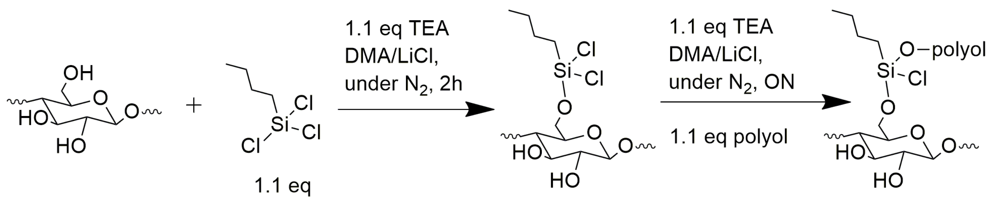
2.2. Preparation of Modified CNCs via Freeze-Drying and Solubilization in DMA/LiCl (FD-CNCs)
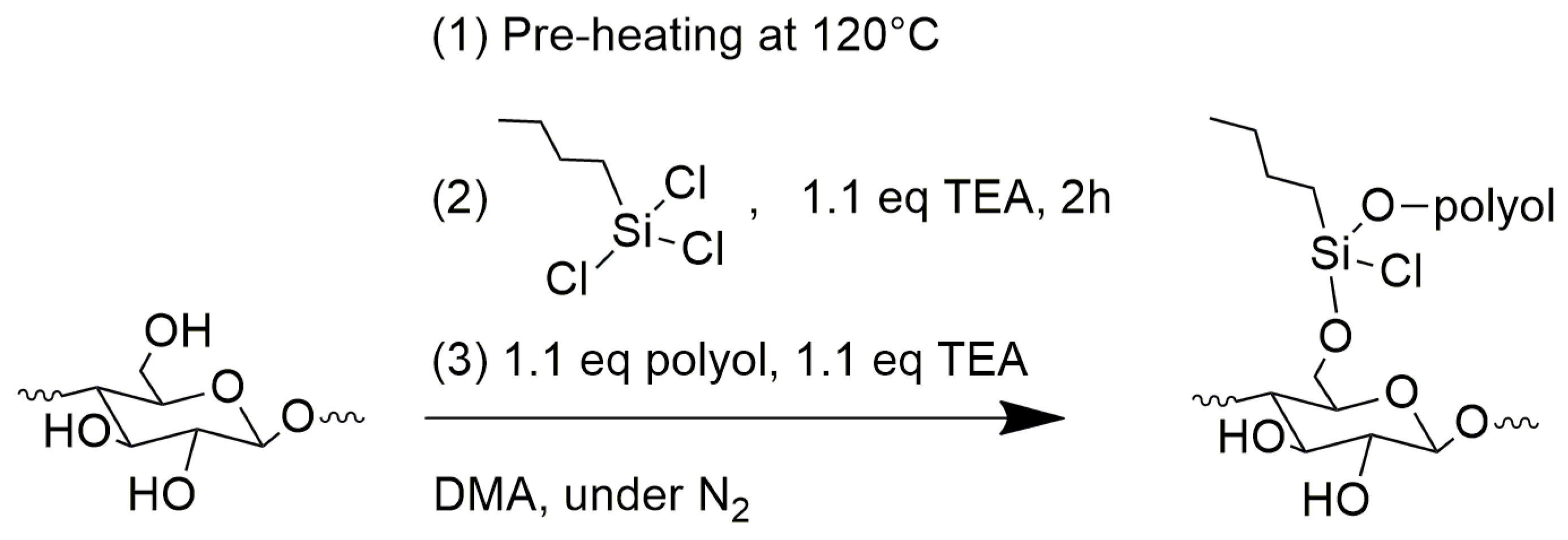
2.3. Preparation of Modified CNC via Solvent Exchange (SE_CNCs)
2.4. Preparation of Bio-Based PUR Foams
2.4.1. CNCs and Polyols Characterizations
2.4.2. Bio-Based PURs Characterizations
3. Results and Discussions
3.1. Filler Characterization
3.2. Foam Characterization
4. Conclusions
Author Contributions
Funding
Institutional Review Board Statement
Data Availability Statement
Acknowledgments
Conflicts of Interest
References
- Coccia, F.; Gryshchuk, L.; Moimare, P.; Bossa, F.d.L.; Santillo, C.; Barak-Kulbak, E.; Verdolotti, L.; Boggioni, L.; Lama, G.C. Chemically Functionalized Cellulose Nanocrystals as Reactive Filler in Bio-Based Polyurethane Foams. Polymers 2021, 13, 2556. [Google Scholar] [CrossRef] [PubMed]
- Santillo, C.; Wang, Y.; Buonocore, G.G.; Gentile, G.; Verdolotti, L.; Kaciulis, S.; Xia, H.; Lavorgna, M. Hybrid Graphene Oxide/Cellulose Nanofillers to Enhance Mechanical and Barrier Properties of Chitosan Based Composites. Front. Chem. 2022, 10, 926364. [Google Scholar] [CrossRef]
- Sanna, V.; Saila, J.; Riku, T.; Harri, H.; Sauli, V. Chemically modified cellulose nanofibril as an additive for two-component polyurethane coatings. J. Appl. Polym. Sci. 2017, 134, 44801–44802. [Google Scholar]
- Available online: https://plasticseurope.org (accessed on 25 October 2022).
- Randall, D.; Lee, S. The Polyurethanes Book; John Wiley & Sons: Hoboken, NJ, USA, 2003. [Google Scholar]
- Verdolotti, L.; Oliviero, M.; Lavorgna, M.; Santillo, C.; Tallia, F.; Iannace, S.; Chen, S.; Jones, J.R. “Aerogel-like” polysiloxane-polyurethane hybrid foams with enhanced mechanical and thermal-insulating properties. Comp. Sci. Technol. 2021, 213, 108917. [Google Scholar] [CrossRef]
- Lee, J.H.; Kim, S.H.; Oh, K.W. Bio-based polyurethane foams with castor oil based multifunctional polyols for improved compressive properties. Polymers 2021, 13, 576. [Google Scholar] [CrossRef]
- Hiba, S.; Xu, X.; Shifa, W. Current progress in production of biopolymeric materials based on cellulose, cellulose nanofibers, and cellulose derivatives. RSC Adv. 2018, 8, 825–842. [Google Scholar]
- De Luca Bossa, F.; Verdolotti, L.; Russo, V.; Campaner, P.; Minigher, A.; Lama, G.C.; Boggioni, L.; Tesser, R.; Lavorgna, M. Upgrading Sustainable Polyurethane Foam Based on Greener Polyols: Succinic-Based Polyol and Mannich-Based Polyol. Materials 2020, 13, 3170. [Google Scholar] [CrossRef] [PubMed]
- Gandhi, T.S.; Patel, M.R.; Dholakiya, B.Z. Synthesis of cashew Mannich polyol via a three step continuous route and development of PU rigid foams with mechanical, thermal and fire studies. J. Polym. Eng. 2015, 35, 533–544. [Google Scholar] [CrossRef]
- Shrestha, M.L.; Ionescu, M.; Wan, X.; Bili´c, N.; Petrovi´c, Z.S.; Upshaw, T. Biobased Aromatic-Aliphatic Polyols from Cardanol by Thermal Thiol-Ene Reaction. J. Renew. Mater. 2018, 6, 87–101. [Google Scholar] [CrossRef]
- Khatoon, H.; Iqbal, S.; Mohd, I.; Darda, A.; Kanwar Rawat, N. A review on the production, properties and applications of non-isocyanate polyurethane: A greener perspective. Prog. Org. Coat. 2021, 154, 106124. [Google Scholar] [CrossRef]
- Peyrton, J.; Avérous, L. Structure-properties relationships of cellular materials from biobased polyurethane foams. Mater. Sci. Eng. R. Rep. 2021, 145, 100608. [Google Scholar] [CrossRef]
- Ma, Y.; Xiao, Y.; Zhao, Y.; Bei, Y.; Hu, L.; Zhou, Y.; Jia, P. Biomass based polyols and biomass based polyurethane materials as a route towards sustainability. React. Funct. Polym. 2022, 175, 105285. [Google Scholar] [CrossRef]
- Polaczek, K.; Kurańska, M.; Prociak, A. Open-cell bio-polyurethane foams based on bio-polyols from used cooking oil. J. Clean. Prod. 2022, 359, 132107. [Google Scholar] [CrossRef]
- Recupido, F.; Lama, G.C.; Ammendola, M.; De Luca Bossa, F.; Minigher, A.; Campaner, P.; Gala Morena, A.; Tzanov, T.; Ornelas, M.; Barros, A.; et al. Rigid composite bio-based polyurethane foams: From synthesis to LCA analysis. Polymer 2023, 267, 125674. [Google Scholar] [CrossRef]
- Stanzione, M.; Russo, V.; Oliviero, M.; Verdolotti, L.; Sorrentino, A.; Di Serio, M.; Tesser, R.; Iannace, S.; Lavorgna, M. Synthesis and characterization of sustainable polyurethane foams based on polyhydroxils with different terminal groups. Polymer 2018, 149, 134–145. [Google Scholar] [CrossRef]
- Agrawal, A.; Raminder, K.; Walia, R.S. PU foam derived from renewable sources: Perspective on properties enhancement: An overview. Eur. Polym. J. 2017, 95, 255–274. [Google Scholar] [CrossRef]
- De Luca Bossa, F.; Santillo, C.; Verdolotti, L.; Campaner, P.; Minigher, A.; Boggioni, L.; Losio, S.; Coccia, F.; Iannace, S.; Lama, G.C. Greener nanocomposite polyurethane foam based on sustainable polyol and natural fillers: Investigation of chemico-physical and mechanical properties. Materials 2020, 131, 211. [Google Scholar] [CrossRef] [PubMed]
- Husainie, S.H.; Deng, X.; Ghalia, M.A.; Robinson, J.; Naguib, H.E. Natural fillers as reinforcement for closed-molded polyurethane foam plaques: Mechanical, morphological, and thermal properties. Mater. Today Commun. 2021, 27, 102187. [Google Scholar] [CrossRef]
- Delucis, R.d.A.; Magalhães, W.L.E.; Petzhold, C.L.; Amico, S.C. Forest-based resources as fillers in biobased polyurethane foams. Appl. Polym. Sci. 2017, 135, 45684. [Google Scholar] [CrossRef]
- Verdolotti, L.; Lavorgna, M.; Di Maio, E.; Iannace, S. Hydration-induced reinforcement of rigid polyurethane cement foams: The effect of the co-continuous morphology on the thermal-oxidative stability. Polym. Deg. Stab. 2013, 98, 64–72. [Google Scholar] [CrossRef]
- Borowicz, M.; Paciorek-Sadowska, J.; Lubczak, J.M.; Czupryński, B. Biodegradable, Flame-Retardant, and Bio-Based Rigid Polyurethane/Polyisocyanurate Foams for Thermal Insulation Application. Polymers 2019, 11, 1816. [Google Scholar] [CrossRef]
- Oliviero, M.; Stanzione, M.M.; D’Auria, M.; Sorrentino, L.; Iannace, S.; Verdolotti, L. Vegetable Tannin as a Sustainable UV Stabilizer for Polyurethane Foams. Polymers 2019, 11, 480. [Google Scholar] [CrossRef] [PubMed] [Green Version]
- Członka, S.; Strąkowska, A.; Kairytė, A.; Kremensas, A. Nutmeg filler as a natural compound for the production of polyurethane composite foams with antibacterial and anti-aging properties. Polym. Test. 2020, 86, 106479. [Google Scholar] [CrossRef]
- Pz Nik Pauzi, N.N.; Majid, R.A.; Dzulkifli, M.H.; Yahya, M.Y. Development of rigid bio-based polyurethane foam reinforced with nanoclay. Comp. Part B Eng. 2014, 67, 521–526. [Google Scholar] [CrossRef]
- Członka, S.; Strąkowska, A.; Kairytė, K. Effect of walnut shells and silanized walnut shells on the mechanical and thermal properties of rigid polyurethane foams. Polym. Test. 2020, 87, 106534. [Google Scholar] [CrossRef]
- Li, Y.; Ragauskas, A.J. Cellulose nano whiskers as a reinforcing filler in polyurethanes. Algae 2011, 75, 10–15. [Google Scholar]
- De Souza, A.G.; Rocha, D.B.; Kano, F.S.; dos Santos Rosa, D. Valorization of industrial paper waste by isolating cellulose nanostructures with different pretreatment methods. Resour. Conserv. Recycl. 2019, 143, 133–142. [Google Scholar] [CrossRef]
- Shojaeiarani, J.; Bajwa, D.S.; Chanda, S. Cellulose nanocrystal based composites: A review. Compos. Part C Open Access 2021, 5, 100164. [Google Scholar] [CrossRef]
- Sture, B.; Vevere, L.; Kirpluks, M.; Godina, D.; Fridrihsone, A.; Cabulis, U. Polyurethane Foam Composites Reinforced with Renewable Fillers for Cryogenic Insulation. Polymers 2021, 13, 4089. [Google Scholar] [CrossRef]
- Li, Y.; Ragauskas, A.J. Ethanol organosolv lignin-based rigid polyurethane foam reinforced with cellulose nanowhiskers. RSC Adv. 2012, 2, 3347–3351. [Google Scholar] [CrossRef]
- Li, Y.; Ren, H.; Ragauskas, A.J. Rigid polyurethane foam reinforced with cellulose whiskers: Synthesis and characterization. Nano-Micro Lett. 2010, 2, 89–94. [Google Scholar] [CrossRef]
- Li, Y.; Ren, H.; Ragauskas, A.J. Rigid polyurethane foam/cellulose whisker nanocomposites: Preparation, characterization, and properties. J. Nanosci. Nanotechnol. 2011, 11, 6904–6911. [Google Scholar] [CrossRef]
- Mishra, R.K.; Ha, S.K.; Verma, K.; Tiwari, S.K. Recent progress in selected bio-nanomaterials and their engineering applications: An overview. J. Sci. Adv. Mater. Dev. 2018, 3, 263–288. [Google Scholar] [CrossRef]
- Zhang, C.; Liu, R.; Xiang, J.; Kang, H.; Liu, Z.; Huang, Y. Dissolution Mechanism of Cellulose in N,N-Dimethylacetamide/Lithium Chloride: Revisiting through Molecular Interactions. J. Phys. Chem. 2014, 118, 9507–9514. [Google Scholar] [CrossRef]
- Kaboorani, A.; Riedl, B. Surface modification of cellulose nanocrystals (CNC) by a cationic surfactant. Ind. Crop. Prod. 2015, 65, 45–55. [Google Scholar] [CrossRef]
- Khoshkava, V.; Kamal, M.R. Effect of Surface Energy on Dispersion and Mechanical Properties of Polymer/Nanocrystalline Cellulose Nanocomposites. Biomacromolecules 2013, 14, 3155–3163. [Google Scholar] [CrossRef]
- Spinella, S.; Samuel, C.; Raquez, J.; McCallum, S.A.; Gross, R.; Dubois, P. Green and Efficient Synthesis of Dispersible Cellulose Nanocrystals in Biobased Polyesters for Engineering Applications. ACS Sustain. Chem. Eng. 2016, 4, 2517–2527. [Google Scholar] [CrossRef]
- Ghasemlou, M.; Daver, F.; Ivanova, E.P.; Habibi, Y.; Adhikari, B. Surface modifications of nanocellulose: From synthesis to high-performance nanocomposites. Prog. Polym. Sci. 2021, 119, 101418–101428. [Google Scholar] [CrossRef]
- Yan, S.; Yin, J.; Dai, Z.; Ma, J.; Chen, X. Surface-grafted silica linked with l-lactic acid oligomer: A novel nanofiller to improve the performance of biodegradable poly(l-lactide). Polymer 2007, 48, 1688–1694. [Google Scholar] [CrossRef]
- Supová, M.; Martynková, G.; Gražyna, S.; Barabaszová, K. Effect of nanofillers dispersion in polymer matrices: A review. Sci. Adv. Mater. 2011, 3, 1–25. [Google Scholar] [CrossRef]
- Ferreira, F.V.; Pinheiro, I.F.; Gouveia, R.F.; Thim, G.P.; Lonal, L.M.F. Functionalized cellulose nanocrystals as reinforcement in biodegradable polymer nanocomposites. Polym. Comp. 2018, 39, 9–29. [Google Scholar] [CrossRef]
- Alinejad, M.; Henry, C.; Nikafshar, S.; Gondaliya, A.; Bagheri, S.; Chen, N.; Singh, S.K.; Hodge, D.B.; Nejad, N. Lignin-Based Polyurethanes: Opportunities for Bio-Based Foams, Elastomers, Coatings and Adhesives. Polymers 2019, 11, 1202. [Google Scholar] [CrossRef]
- Javni, I.; Zhang, W.; Karajkov, V.; Petrovic, Z.S. Effect of Nano-and Micro-Silica Fillers on Polyurethane Foam Properties. J. Cell Plast. 2016, 38, 229–239. [Google Scholar] [CrossRef]
- Stanzione, M.M.; Oliviero, M.; Cocca, M.; Errico, M.E.; Gentile, G.; Avella, M.; Lavorgna, M.; Buonocore, G.G.; Verdolotti, L. Tuning of polyurethane foam mechanical and thermal properties using ball-milled cellulose. Carb. Polym. 2020, 231, 115772. [Google Scholar] [CrossRef]
- Zhai, T.; Verdolotti, L.; Kacilius, S.; Cerruti, P.; Gentile, G.; Xia, H.; Stanzione, M.; Buonocore, G.G.; Lavorgna, M. High piezo-resistive performances of anisotropic composites realized by embedding rGO-based chitosan aerogels into open cell polyurethane foams. Nanoscale 2019, 11, 8835. [Google Scholar] [CrossRef] [PubMed]
- Grzabka-Zasadzinska, A.; Bartczak, P.; Borysiak, S. Highly Insulative PEG-Grafted Cellulose Polyurethane Foams—From Synthesis to Application Properties. Materials 2021, 14, 6363. [Google Scholar] [CrossRef]
- Dupont, A.L. Cellulose in lithium chloride/N, N-dimethylacetamide, optimisation of a dissolution method using paper substrates and stability of the solutions. Polymer 2003, 44, 4117–4126. [Google Scholar] [CrossRef]
- Sadeghifar, H.; Venditti, R.A.; Pawlak, J.J.; Jur, J. Cellulose transparent and flexible films prepared from DMAc/LiCl solutions. BioResources 2019, 14, 9021–9032. [Google Scholar]
- Le Gars, M.; Roger, P.; Belgacem, N.; Bras, J. Role of solvent exchange in dispersion of cellulose nanocrystals and their esterification using fatty acids as solvents. Cellulose 2019, 27, 4319–4336. [Google Scholar] [CrossRef]
- Jonjaroen, V.; Ummartyotin, S.; Chittapun, S. Algal cellulose as a reinforcement in rigid polyurethane foam. Alga Res. 2020, 51, 102057. [Google Scholar] [CrossRef]
- Furtwengler, P.; Averous, L. Renewable polyols for advanced polyurethane foams from diverse biomass resources. Polym. Chem. 2018, 9, 4258–4287. [Google Scholar] [CrossRef]
- Available online: https://www.admet.com/testing-applications/testing-standards/astm-d1621-plastic-compression (accessed on 25 October 2022).
- Gibson, L.J.; Ashby, M.F. The mechanics of foams: Basic results. In Cellular Solids: Structure and Properties; Cambridge University Press: Cambridge, UK, 1997; pp. 175–234. [Google Scholar]
- Benedetti, M.; Klarin, J.; Johansson, F.; Fontanari, V.; Luchin, V.; Zappini, G.; Molinari, A. Study of the compression behaviour of Ti6Al4V trabecular structures produced by additive laser manufacturing. Materials 2019, 12, 1471. [Google Scholar] [CrossRef]
- Ashby, M.F.; Medalist, R.F. The mechanical properties of cellular solids. Metall. Trans. A 1983, 14, 1755–1769. [Google Scholar] [CrossRef]
- Bellani, C.F.; Pollet, E.; Hebraud, A.; Pereira, F.V.; Schlatter, G.; Avérous, L.; Bretas, R.E.S.; Branciforti, M.C. Morphological, thermal, and mechanical properties of poly(ε-caprolactone)/poly(ε-caprolactone)-grafted-cellulose nanocrystals mats produced by electrospinning. Appl. Polym. Sci. 2016, 133, 43445. [Google Scholar] [CrossRef]
- Andersons, J.; Kirpluks, M.; Cabulis, P.; Kalnins, K.; Cabulis, U. Bio-based rigid high-density polyurethane foams as a structural thermal break material. Const. Build. Mater. 2020, 260, 120471. [Google Scholar] [CrossRef]
- Septevani, A.A.; Evans, D.A.C.; Annamalai, P.T.; Martin, D.J. The use of cellulose nanocrystals to enhance the thermal insulation properties and sustainability of rigid polyurethane foam. Ind. Crop. Prod. 2017, 17, 114–121. [Google Scholar] [CrossRef]
- Uram, K.; Leszczyńska, M.; Prociak, A.; Czajka, A.; Gloc, M.; Leszczyński, M.K.; Michałowski, M.; Ryszkowska, J. Polyurethane Composite Foams Synthesized Using Bio-Polyols and Cellulose Filler. Materials 2021, 14, 3474. [Google Scholar] [CrossRef]
- Modesti, M.; Lorenzetti, A.; Besco, S. Influence of Nanofillers on Thermal Insulating Properties of Polyurethane Nanocomposites Foams. Polym. Sci. Eng. 2007, 47, 1351–1358. [Google Scholar] [CrossRef]
- Strakowska, A.; Członka, S.; Strzelec, K. POSS Compounds as Modifiers for Rigid Polyurethane Foams (Composites). Polymers 2019, 11, 1092. [Google Scholar] [CrossRef]
- Gibson, L.J. Modelling the mechanical behavior of cellular materials. Mater. Sci. Eng. A 1989, 110, 1–36. [Google Scholar] [CrossRef]
- Bo-Yuan, S.; Chun-Min, H.; Hao, S.; Wen-Yea, J. The effect of cell-size dispersity on the mechanical properties of closed-cell aluminum foam. Mater. Charact. 2018, 135, 203–213. [Google Scholar]
- Gong, W.; Jiang, T.-H.; Xiang-Bu, Z.; He, L.; Zhang, C. Experimental-numerical studies of the effect of cell structure on the mechanical properties of polypropylene foams. E-Polymers 2020, 20, 713–723. [Google Scholar] [CrossRef]
- Członka, S.; Kairytė, A.; Miedzinska, K.; Strąkowska, A.; Adamus-Włodarczyk, A. Mechanically Strong Polyurethane Composites Reinforced with Montmorillonite-Modified Sage Filler (Salvia officinalis L.). Int. J. Mol. Sci. 2021, 22, 3744. [Google Scholar] [CrossRef] [PubMed]


| Modified-CNCs | Polyol | Modification |
|---|---|---|
| FD_CNC1 | NX9203 | Freeze drying/Solubilization in DMA/LiCl/Sylanization |
| FD_CNC2 | NX9201 | Freeze drying/Solubilization in DMA/LiCl/Sylanization |
| SE_CNC1 | NX9203 | Solvent Exchange/Sylanization |
| SE_CNC2 | NX9201 | Solvent Exchange/Sylanization |
| Components | PUR Pristine (%) | PUR_FD_0 (%) | PUR_SE_0 (%) | PUR_SE_1 (%) | PUR_SE_2 (%) | PUR_FD_1 (%) | PUR_FD_2 (%) |
|---|---|---|---|---|---|---|---|
| Component A | |||||||
| BI6121 | 40.8 | 38.3 | 38.3 | 38.3 | 38.3 | 38.3 | 38.3 |
| Niax PM 40 | 0.4 | 0.4 | 0.4 | 0.4 | 0.4 | 0.4 | 0.4 |
| CH3COOK | 0.4 | 0.4 | 0.4 | 0.4 | 0.4 | 0.4 | 0.4 |
| Niax L6900 | 0.4 | 0.4 | 0.4 | 0.4 | 0.4 | 0.4 | 0.4 |
| TCPP | 4 | 4 | 4 | 4 | 4 | 4 | 4 |
| H2O | 0.4 | 0.4 | 0.4 | 0.4 | 0.4 | 0.4 | 0.4 |
| Filler * | - | 5.1 | 5.1 | 5.1 | 5.1 | 5.1 | 5.1 |
| Component B | |||||||
| MDI | 53.5 | 51.0 | 51.0 | 51.0 | 51.0 | 51.0 | 51.0 |
| Samples | λ (W/mK) |
|---|---|
| PUR pristine | 0.039 ± 0.002 |
| PUR_FD_0 | 0.041 ± 0.005 |
| PUR_FD_1 | 0.027 ± 0.007 |
| PUR_FD_2 | 0.034 ± 0.009 |
| σ (10%) (MPa) | E (MPa) | ρ (kg m−3) | σ (10%)/ρ (MPa/kg m−3) | E/ρ (MPa/kg m−3) | |
|---|---|---|---|---|---|
| PUR pristine | 0.42 ± 0.03 | 8.03 ± 0.53 | 85.19 ± 3.02 | 4.93 | 94.27 |
| PUR_FD_0 | 0.28 ± 0.02 | 3.74 ± 0.16 | 82.57 ± 1.11 | 3.39 | 45.29 |
| PUR_FD_1 | 0.70 ± 0.05 | 9.26 ± 0.41 | 94.19 ± 3.97 | 7.43 | 98.31 |
| PUR_FD_2 | 0.39 ± 0.04 | 5.77 ± 0.39 | 91.18 ± 4.13 | 4.28 | 63.28 |
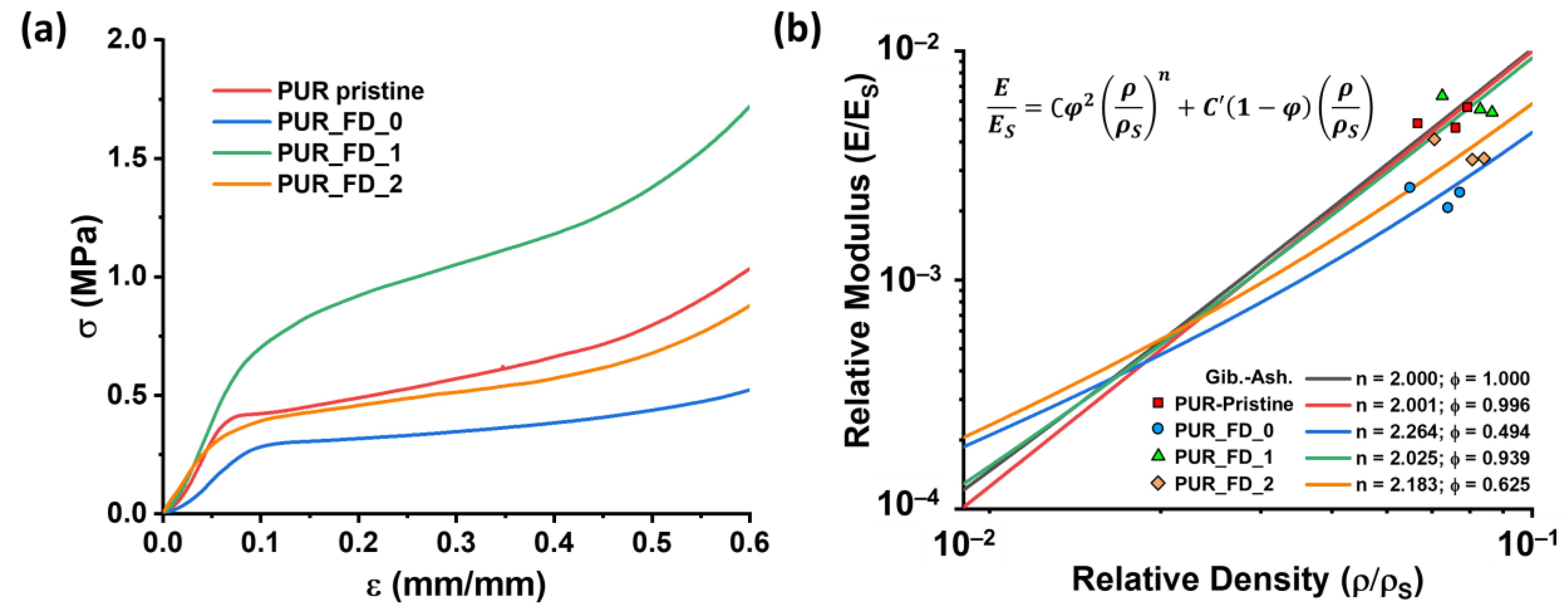
| Material | E/ES | ρ/ρS | n | C | C’ | φ |
|---|---|---|---|---|---|---|
| PUR_Pristine | 0.0050 | 0.0710 | 2.0015 | 1.0041 | 0.0707 | 0.9959 |
| PUR_FD_0 | 0.0023 | 0.0688 | 2.2637 | 2.0255 | 0.0340 | 0.4937 |
| PUR_FD_1 | 0.0058 | 0.0785 | 2.0246 | 1.0646 | 0.0737 | 0.9393 |
| PUR_FD_2 | 0.0036 | 0.0760 | 2.1826 | 1.6009 | 0.0475 | 0.6247 |
Disclaimer/Publisher’s Note: The statements, opinions and data contained in all publications are solely those of the individual author(s) and contributor(s) and not of MDPI and/or the editor(s). MDPI and/or the editor(s) disclaim responsibility for any injury to people or property resulting from any ideas, methods, instructions or products referred to in the content. |
© 2023 by the authors. Licensee MDPI, Basel, Switzerland. This article is an open access article distributed under the terms and conditions of the Creative Commons Attribution (CC BY) license (https://creativecommons.org/licenses/by/4.0/).
Share and Cite
Fontana, D.; Recupido, F.; Lama, G.C.; Liu, J.; Boggioni, L.; Silvano, S.; Lavorgna, M.; Verdolotti, L. Effect of Different Methods to Synthesize Polyol-Grafted-Cellulose Nanocrystals as Inter-Active Filler in Bio-Based Polyurethane Foams. Polymers 2023, 15, 923. https://doi.org/10.3390/polym15040923
Fontana D, Recupido F, Lama GC, Liu J, Boggioni L, Silvano S, Lavorgna M, Verdolotti L. Effect of Different Methods to Synthesize Polyol-Grafted-Cellulose Nanocrystals as Inter-Active Filler in Bio-Based Polyurethane Foams. Polymers. 2023; 15(4):923. https://doi.org/10.3390/polym15040923
Chicago/Turabian StyleFontana, Dario, Federica Recupido, Giuseppe Cesare Lama, Jize Liu, Laura Boggioni, Selena Silvano, Marino Lavorgna, and Letizia Verdolotti. 2023. "Effect of Different Methods to Synthesize Polyol-Grafted-Cellulose Nanocrystals as Inter-Active Filler in Bio-Based Polyurethane Foams" Polymers 15, no. 4: 923. https://doi.org/10.3390/polym15040923