
Design and Behavior of Lightweight Flexible Structure with Spatial Pattern Reducing Contact Surface Fraction
 , , , , ,
Abstract
:1. Introduction
2. Materials and Methods
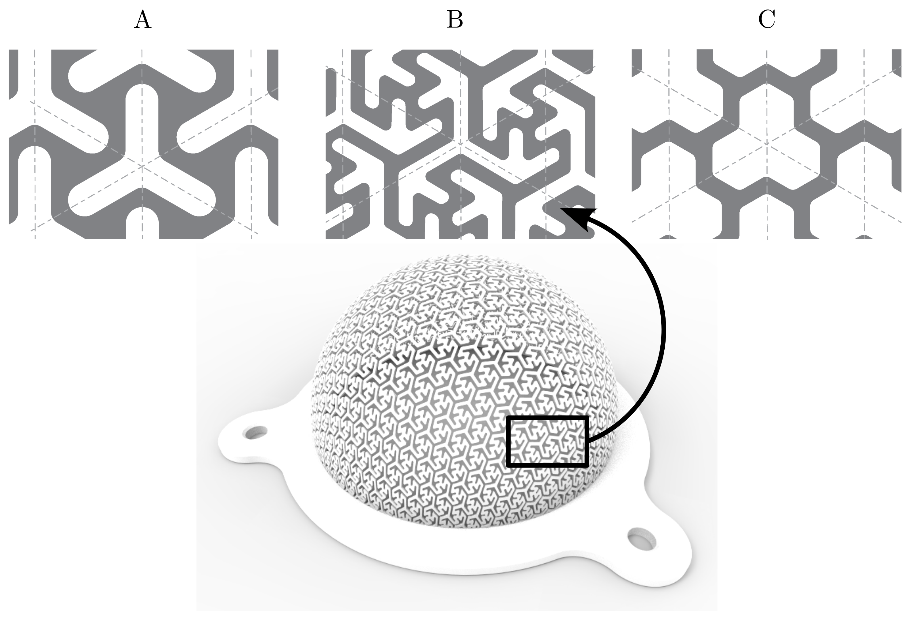
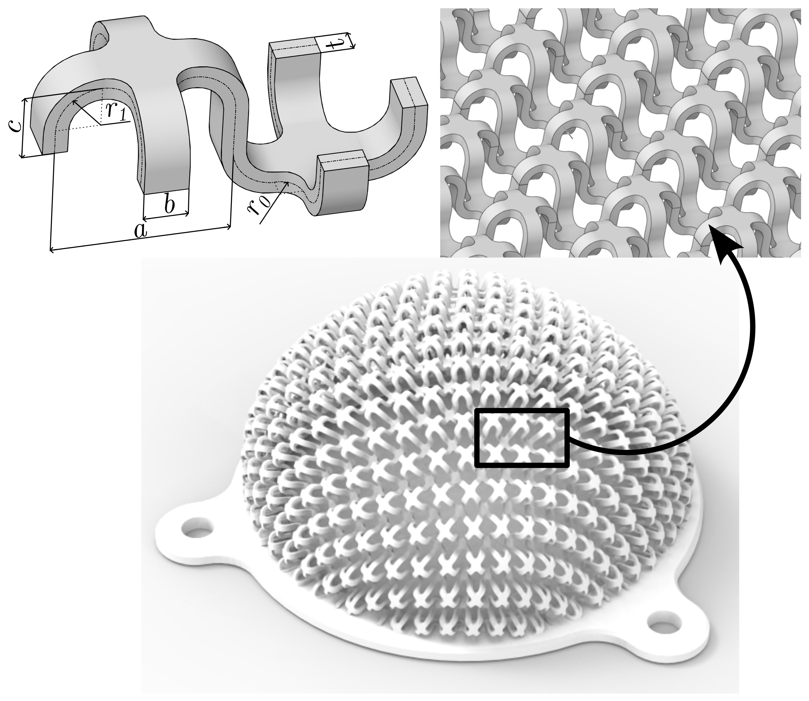
2.1. Design of the Spatial Pattern for the Lightweight Flexible Structure
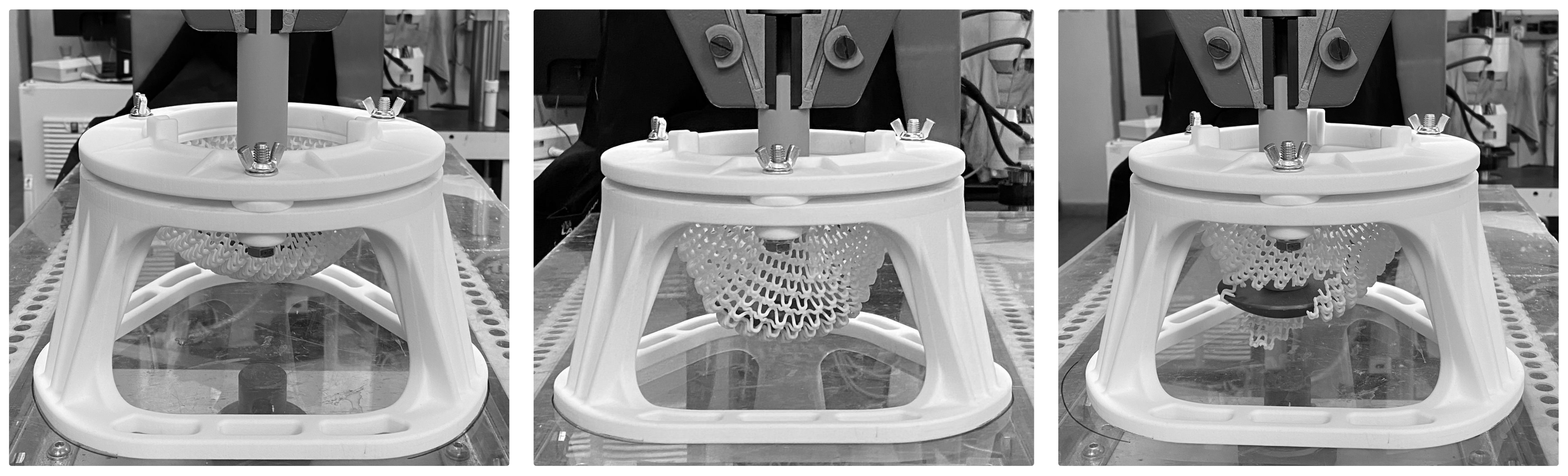
2.2. Laboratory Testing of the 3D-Printed Lightweight Structure
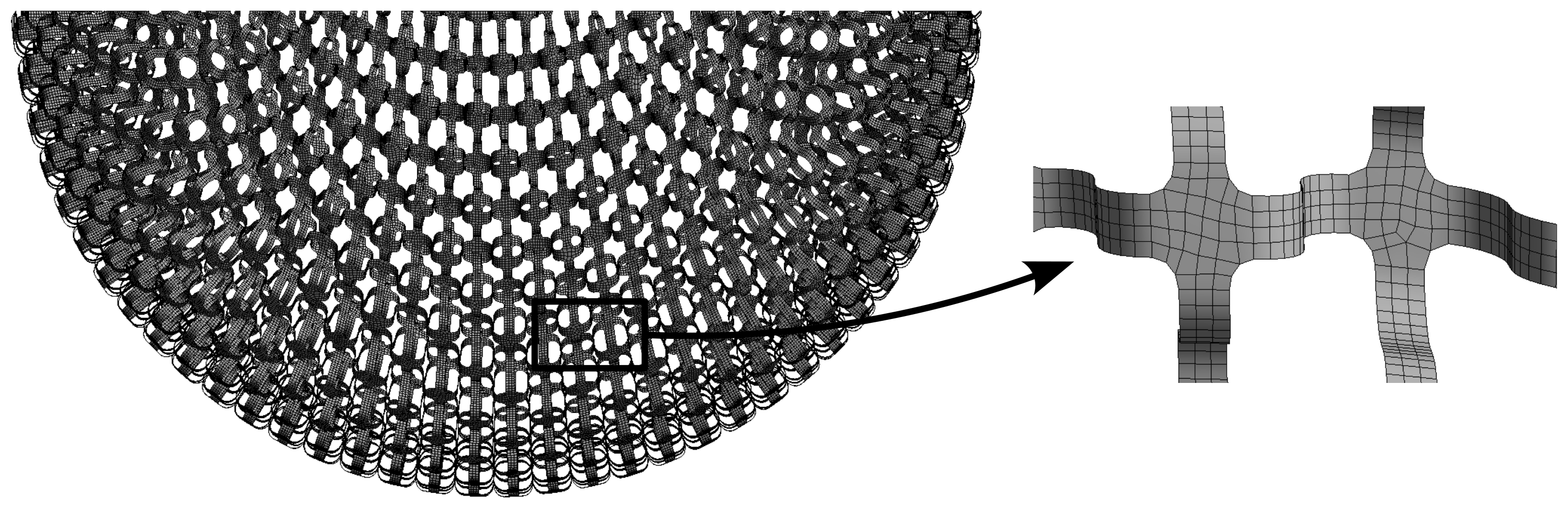
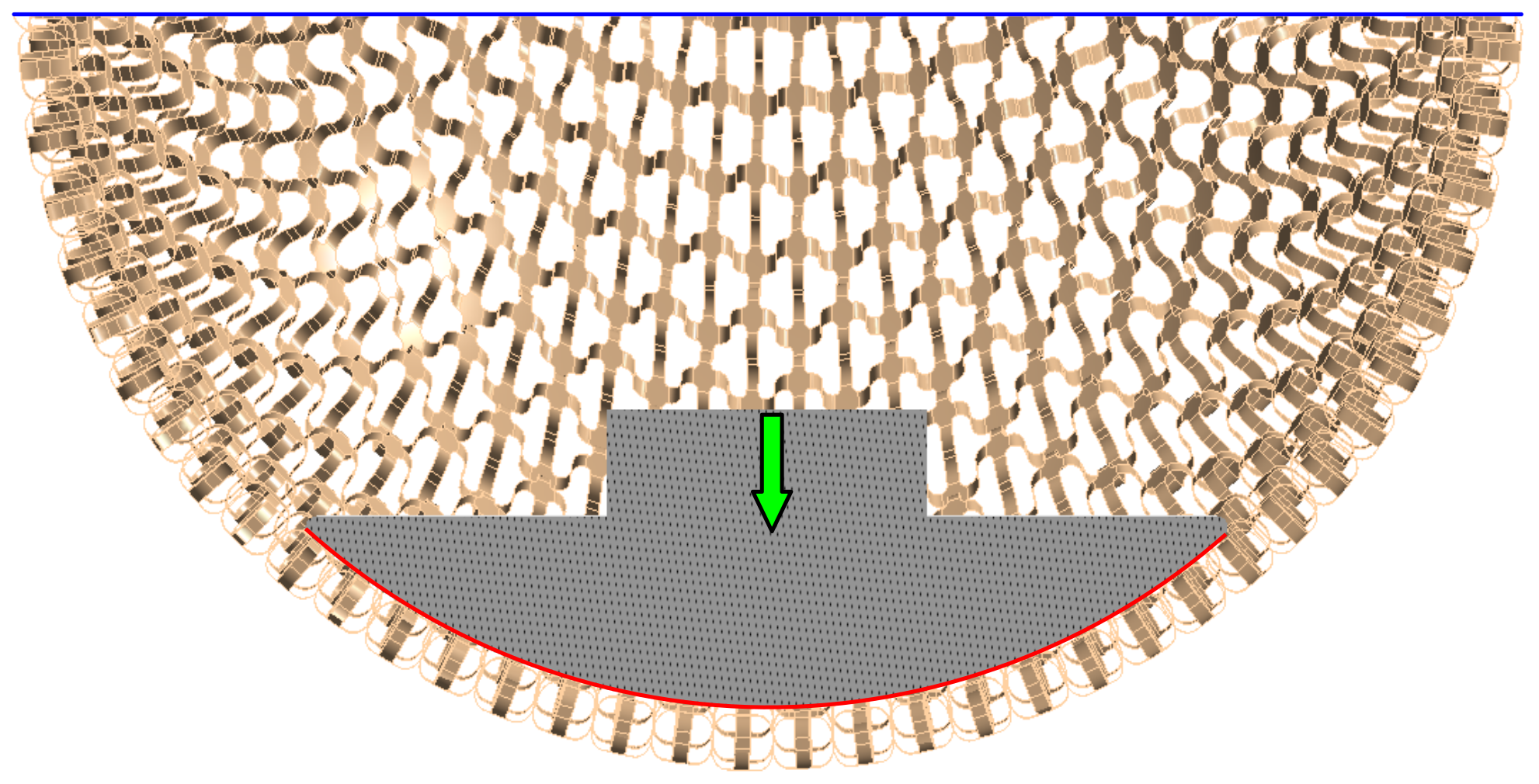
2.3. Numerical Modelling of the Lightweight Structure
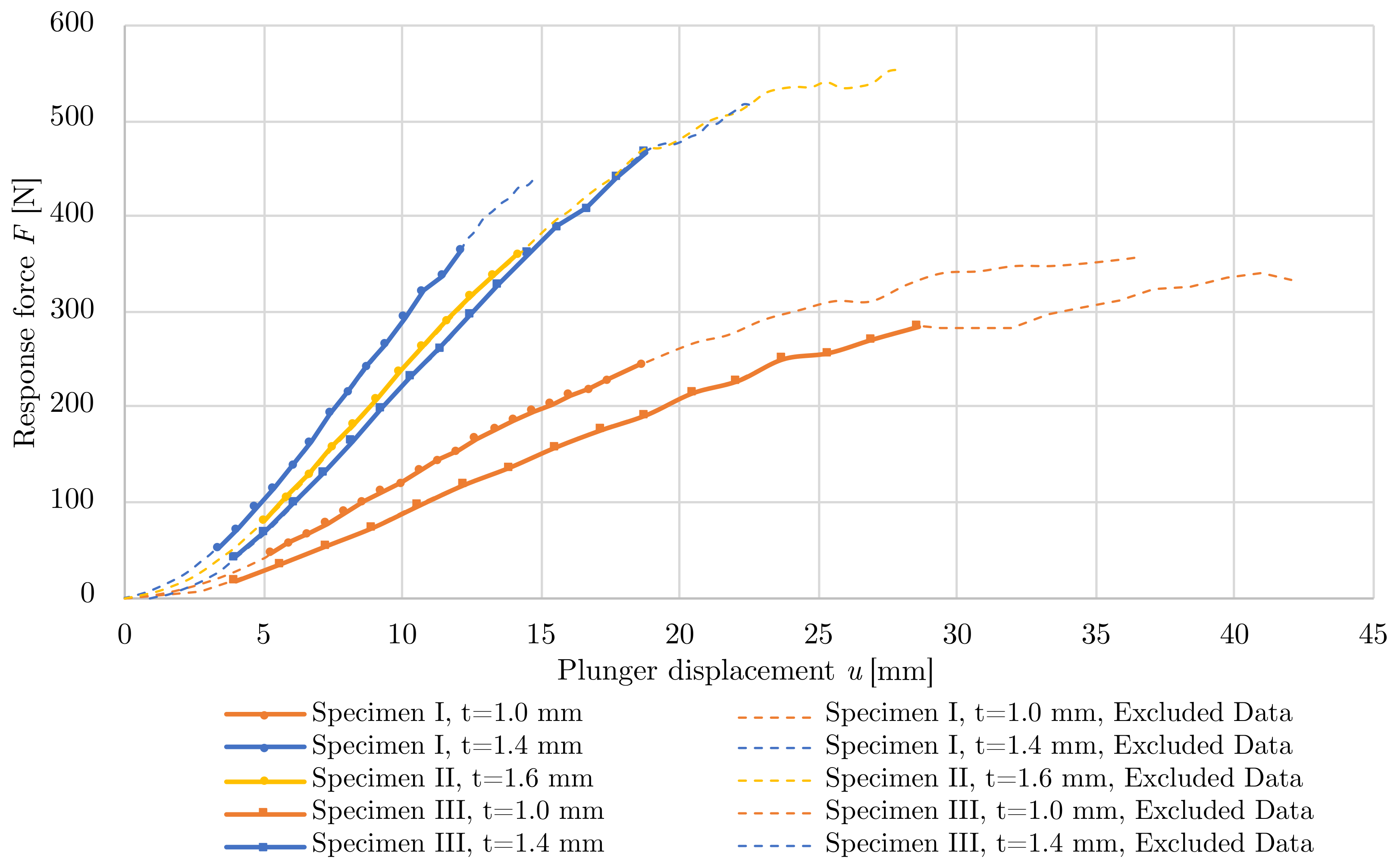
3. Results
4. Discussion
5. Conclusions
Author Contributions
Funding
Institutional Review Board Statement
Data Availability Statement
Conflicts of Interest
Abbreviations
| 2D | 2-Dimensional |
| 3D | 3-Dimensional |
| AM | Additive Manufacturing |
| AWB | Ansys Workbench 2021R2 |
| CA | California |
| CAD | Computer-Aided Design |
| FDM | Fused Deposition Modeling |
| FS | Flexible Structure |
| LBC | Load-Bearing Capacity |
| LFS | Lightweight Flexible Structure |
| PLA | Polylactil Acid |
| PA12 | Polyamide 12 |
| RAM | Random-Access Memory |
| SLS | Selective Laser Sintering |
| STL | Standard Triangle Language |
| UK | United Kingdom |
| USA | United States of America |
| WA | Washington |
References
- Seharing, A.; Azman, A.H.; Abdullah, S. A review on integration of lightweight gradient lattice structures in additive manufacturing parts. Adv. Mech. Eng. 2020, 12, 1687814020916951. [Google Scholar] [CrossRef]
- Sharma, S.; Singh, J.; Kumar, H.; Sharma, A.; Aggarwal, V.; Gill, A.S.; Jayarambabu, N.; Kailasa, S.; Rao, K.V. Utilization of rapid prototyping technology for the fabrication of an orthopedic shoe inserts for foot pain reprieve using thermo-softening viscoelastic polymers: A novel experimental approach. Meas. Control 2020, 53, 519–530. [Google Scholar] [CrossRef]
- Lin, K.W.; Hu, C.J.; Yang, W.W.; Chou, L.W.; Wei, S.H.; Chen, C.S.; Sun, P.C. Biomechanical Evaluation and Strength Test of 3D-Printed Foot Orthoses. Appl. Bionics Biomech. 2019, 2019, 4989534. [Google Scholar] [CrossRef] [PubMed]
- Prokop, J.; Marsalek, P.; Sengul, I.; Pelikan, A.; Janoutova, J.; Horyl, P.; Roman, J.; Sengul, D.; Junior, J.M.S. Evaluation of breast stiffness pathology based on breast compression during mammography: Proposal for novel breast stiffness scale classification. Clinics 2022, 77, 100100. [Google Scholar] [CrossRef] [PubMed]
- Holmes, D.W.; Singh, D.; Lamont, R.; Daley, R.; Forrestal, D.P.; Slattery, P.; Pickering, E.; Paxton, N.C.; Powell, S.K.; Woodruff, M.A. Mechanical behaviour of flexible 3D printed gyroid structures as a tuneable replacement for soft padding foam. Addit. Manuf. 2022, 50, 102555. [Google Scholar] [CrossRef]
- Sotola, M.; Stareczek, D.; Rybansky, D.; Prokop, J.; Marsalek, P. New Design Procedure of Transtibial Prosthesis Bed Stump Using Topological Optimization Method. Symmetry 2020, 12, 1837. [Google Scholar] [CrossRef]
- Sotola, M.; Marsalek, P.; Rybansky, D.; Fusek, M.; Gabriel, D. Sensitivity Analysis of Key Formulations of Topology Optimization on an Example of Cantilever Bending Beam. Symmetry 2021, 13, 712. [Google Scholar] [CrossRef]
- Kundera, C.; Kozior, T. Evaluation of the influence of selected parameters of Selective Laser Sintering technology on surface topography. J. Phys. Conf. Ser. 2019, 1183, 012002. [Google Scholar] [CrossRef]
- Kundera, C.; Kozior, T. Mechanical properties of models prepared by SLS technology. AIP Conf. Proc. 2018, 2017, 020012. [Google Scholar] [CrossRef]
- Saharudin, M.S.; Hajnys, J.; Kozior, T.; Gogolewski, D.; Zmarzły, P. Quality of Surface Texture and Mechanical Properties of PLA and PA-Based Material Reinforced with Carbon Fibers Manufactured by FDM and CFF 3D Printing Technologies. Polymers 2021, 13, 1671. [Google Scholar] [CrossRef]
- Mesicek, J.; Ma, Q.P.; Hajnys, J.; Zelinka, J.; Pagac, M.; Petru, J.; Mizera, O. Abrasive Surface Finishing on SLM 316L Parts Fabricated with Recycled Powder. Appl. Sci. 2021, 11, 2869. [Google Scholar] [CrossRef]
- Bacciaglia, A.; Ceruti, A.; Liverani, A. Surface smoothing for topological optimized 3D models. Struct. Multidiscip. Optim. 2021, 64, 3453–3472. [Google Scholar] [CrossRef]
- Wang, P.; Yang, J.; Hu, Y.; Huo, J.; Feng, X. Innovative design of a helmet based on reverse engineering and 3D printing. Alex. Eng. J. 2021, 60, 3445–3453. [Google Scholar] [CrossRef]
- Jafferson, J.; Pattanashetti, S. Use of 3D printing in production of personal protective equipment (PPE)—A review. Mater. Today Proc. 2021, 46, 1247–1260. [Google Scholar] [CrossRef]
- Sharma, D.; Hiremath, S.S. Bio-inspired repeatable lattice structures for energy absorption: Experimental and finite element study. Compos. Struct. 2022, 283, 115102. [Google Scholar] [CrossRef]
- Pan, C.; Han, Y.; Lu, J. Design and Optimization of Lattice Structures: A Review. Appl. Sci. 2020, 10, 6374. [Google Scholar] [CrossRef]
- Vasiliev, V.; Razin, A. Anisogrid composite lattice structures for spacecraft and aircraft applications. Compos. Struct. 2006, 76, 182–189. [Google Scholar] [CrossRef]
- Alqahtani, S.; Ali, H.M.; Farukh, F.; Kandan, K. Experimental and computational analysis of polymeric lattice structure for efficient building materials. Appl. Therm. Eng. 2023, 218, 119366. [Google Scholar] [CrossRef]
- Fernandez-Vicente, M.; Calle, W.; Ferrandiz, S.; Conejero, A. Effect of Infill Parameters on Tensile Mechanical Behavior in Desktop 3D Printing. 3D Print. Addit. Manuf. 2016, 3, 183–192. [Google Scholar] [CrossRef]
- Tao, W.; Leu, M.C. Design of lattice structure for additive manufacturing. In Proceedings of the 2016 International Symposium on Flexible Automation (ISFA), Cleveland, OH, USA, 1–3 August 2016; pp. 325–332. [Google Scholar] [CrossRef]
- Ali, M.H.; Smagulov, Z.; Otepbergenov, T. Finite element analysis of the CFRP-based 3D printed ankle-foot orthosis. Procedia Comput. Sci. 2021, 179, 55–62. [Google Scholar] [CrossRef]
- Panetta, J.; Zhou, Q.; Malomo, L.; Pietroni, N.; Cignoni, P.; Zorin, D. Elastic Textures for Additive Fabrication. ACM Trans. Graph. 2015, 34, 1–12. [Google Scholar] [CrossRef]
- Schumacher, C.; Thomaszewski, B.; Gross, M. Stenciling: Designing Structurally-Sound Surfaces with Decorative Patterns. Comput. Graph. Forum 2016, 35, 101–110. [Google Scholar] [CrossRef]
- Schumacher, C.; Marschner, S.; Gross, M.; Thomaszewski, B. Mechanical Characterization of Structured Sheet Materials. ACM Trans. Graph. 2018, 37, 1–15. [Google Scholar] [CrossRef]
- Kantaros, A.; Piromalis, D. Fabricating Lattice Structures via 3D Printing: The Case of Porous Bio-Engineered Scaffolds. Appl. Mech. 2021, 2, 289–302. [Google Scholar] [CrossRef]
- Marsalek, P.; Sotola, M.; Rybansky, D.; Repa, V.; Halama, R.; Fusek, M.; Prokop, J. Modeling and Testing of Flexible Structures with Selected Planar Patterns Used in Biomedical Applications. Materials 2021, 14, 140. [Google Scholar] [CrossRef] [PubMed]
- Kusnir, O. Modelling of 3D Printed Spatial Structures. Master’s Thesis, VSB-Technical University of Ostrava, Ostrava, Czech Republic, 2021. [Google Scholar]
- Rybansky, D.; Sotola, M.; Marsalek, P.; Drahorad, L.; Hroncek, J.; Kusnir, O. Modelling and Testing of 3D Printed Flexible Structure with Spatial Pattern; Experimental Stress Analysis 2022 Book of Extended Abstract, 1st ed.; Czech Technical University in Prague, Faculty of Mechanical Engineering, Department of Mechanics, Biomechanics and Mechatronics: Prague, Czech Republic, 2022; pp. 118–119. ISBN 978-80-01-07010-9. [Google Scholar]
- Stoia, D.I.; Linul, E.; Marsavina, L. Influence of Manufacturing Parameters on Mechanical Properties of Porous Materials by Selective Laser Sintering. Materials 2019, 12, 871. [Google Scholar] [CrossRef] [PubMed]
- Kundera, C.; Kozior, T. Research of the Elastic Properties of Bellows Made in SLS Technology. Adv. Mater. Res. 2014, 874, 77–81. [Google Scholar] [CrossRef]
- Hroncek, J.; Marsalek, P.; Rybansky, D.; Sotola, M.; Drahorad, L.; Lesnak, M.; Fusek, M. Simplified Numerical Model for Determining Load-Bearing Capacity of Steel-Wire Ropes. Materials 2023, 16, 3756. [Google Scholar] [CrossRef]
- Cech, R.; Horyl, P.; Marsalek, P. Modelling of Two-Seat Connection to the Frame of Rail Wagon in Terms of Resistance at Impact Test. Stroj. Cas. J. Mech. Eng. 2016, 66, 101–106. [Google Scholar] [CrossRef]
- Lesnak, M.; Marsalek, P.; Horyl, P.; Pistora, J. Load-bearing capacity modelling and testing of single-stranded wire rope. Acta Montan. Slovaca 2020, 25, 192–200. [Google Scholar] [CrossRef]
- Rybansky, D.; Sotola, M.; Marsalek, P.; Poruba, Z.; Fusek, M. Study of Optimal Cam Design of Dual-Axle Spring-Loaded Camming Device. Materials 2021, 14, 1940. [Google Scholar] [CrossRef]
- Morales-Planas, S.; Minguella-Canela, J.; Lluma-Fuentes, J.; Travieso-Rodriguez, J.A.; García-Granada, A.A. Multi Jet Fusion PA12 Manufacturing Parameters for Watertightness, Strength and Tolerances. Materials 2018, 11, 1472. [Google Scholar] [CrossRef]
- Kinstlinger, I.S.; Bastian, A.; Paulsen, S.J.; Hwang, D.H.; Ta, A.H.; Yalacki, D.R.; Schmidt, T.; Miller, J.S. Open-Source Selective Laser Sintering (OpenSLS) of Nylon and Biocompatible Polycaprolactone. PLoS ONE 2016, 11, e0147399. [Google Scholar] [CrossRef]


| Pattern | Stiffness [N/mm] | Thickness [mm] | Contact Surface Fraction [−] |
|---|---|---|---|
| A | 57.52 ÷ 208.22 | 44.4% ± 3% | |
| B | 3.98 ÷ 12.46 | 0.80 ÷ 2.05 | 51.4% ± 5% |
| C | 47.72 ÷ 169.74 | 22.4% ± 2% |
| Variant | a [mm] | b [mm] | c [mm] | [mm] | [mm] | Contact Surface Fraction [−] |
|---|---|---|---|---|---|---|
| I | 7.4 | 1.8 | 2.5 | 0.9 | 1.9 | |
| II | 8.0 | 2.0 | 3.2 | 1.0 | 2.0 | 10% ± 1% |
| III | 8.6 | 2.2 | 3.0 | 1.1 | 2.1 |
| Symbol | E [MPa] | [−] | [kg m] | [MPa] | [MPa] |
|---|---|---|---|---|---|
| Value | 1224 | 0.39 | 1010 | 21 | 334 |
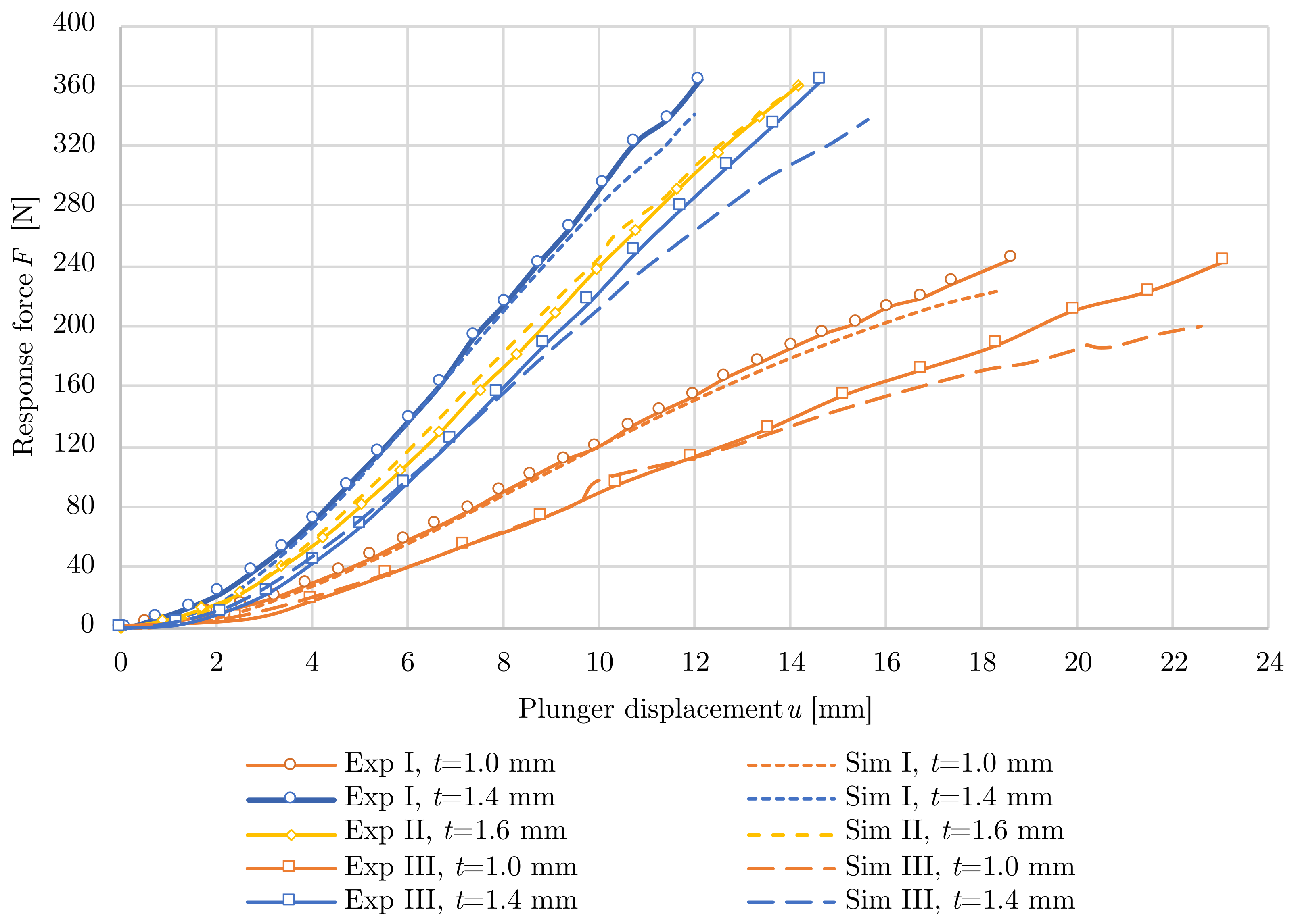
| Specimen | Thickness [mm] | Measured Stiffness [N/mm] | Load Bearing Capacity [N] |
|---|---|---|---|
| I | 1.40 1.00 | 36.82 15.06 | 450 357 |
| II | 1.60 | 31.97 | 554 |
| III | 1.40 1.00 | 29.04 11.25 | 520 343 |
| Specimen | Thickness [mm] | Measured Stiffness [N/mm] | Simulated Stiffness [N/mm] | Stiffness Difference [%] |
|---|---|---|---|---|
| I | 1.40 1.00 | 36.82 15.06 | 35.89 14.68 | 2.53 2.52 |
| II | 1.60 | 31.97 | 32.05 | 0.25 |
| III | 1.40 1.00 | 29.04 11.25 | 28.38 11.7 | 2.27 4.00 |
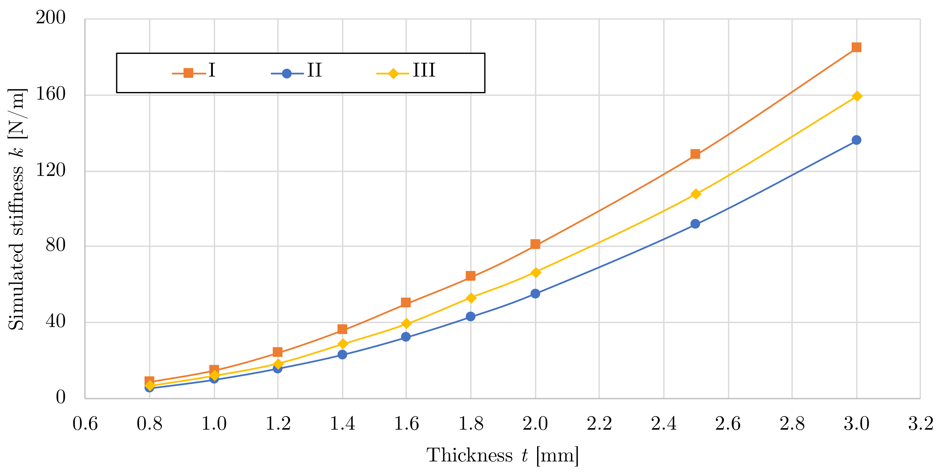
| Variant | Simulated Thickness t [mm] | ||||||||
|---|---|---|---|---|---|---|---|---|---|
| 3.0 | 2.5 | 2.0 | 1.8 | 1.6 | 1.4 | 1.2 | 1.0 | 0.8 | |
| I | 184.97 | 128.56 | 80.65 | 64.00 | 49.99 | 35.89 | 24.03 | 14.68 | 8.61 |
| II | 135.79 | 91.72 | 55.06 | 42.84 | 32.05 | 22.79 | 15.51 | 9.56 | 5.06 |
| III | 159.02 | 107.60 | 66.45 | 52.98 | 39.09 | 28.38 | 18.22 | 11.70 | 6.38 |
Disclaimer/Publisher’s Note: The statements, opinions and data contained in all publications are solely those of the individual author(s) and contributor(s) and not of MDPI and/or the editor(s). MDPI and/or the editor(s) disclaim responsibility for any injury to people or property resulting from any ideas, methods, instructions or products referred to in the content. |
© 2023 by the authors. Licensee MDPI, Basel, Switzerland. This article is an open access article distributed under the terms and conditions of the Creative Commons Attribution (CC BY) license (https://creativecommons.org/licenses/by/4.0/).
Share and Cite
Rybansky, D.; Marsalek, P.; Sotola, M.; Hroncek, J.; Drahorad, L.; Kusnir, O.; Prokop, J. Design and Behavior of Lightweight Flexible Structure with Spatial Pattern Reducing Contact Surface Fraction. Polymers 2023, 15, 3896. https://doi.org/10.3390/polym15193896
Rybansky D, Marsalek P, Sotola M, Hroncek J, Drahorad L, Kusnir O, Prokop J. Design and Behavior of Lightweight Flexible Structure with Spatial Pattern Reducing Contact Surface Fraction. Polymers. 2023; 15(19):3896. https://doi.org/10.3390/polym15193896
Chicago/Turabian StyleRybansky, David, Pavel Marsalek, Martin Sotola, Juraj Hroncek, Lukas Drahorad, Ondrej Kusnir, and Jiri Prokop. 2023. "Design and Behavior of Lightweight Flexible Structure with Spatial Pattern Reducing Contact Surface Fraction" Polymers 15, no. 19: 3896. https://doi.org/10.3390/polym15193896