
The Effect of Transparent Conducting Oxide Films on WO3-Based Electrochromic Devices with Conducting Polymer Electrolytes
 , , ,
, , ,
Abstract
:1. Introduction
2. Materials and Methods
2.1. Materials
2.2. The Fabrication of WO3 Films on Different TCOs
2.3. The Study of the EC Properties of WO3-Based ECDs
3. Results and Discussions
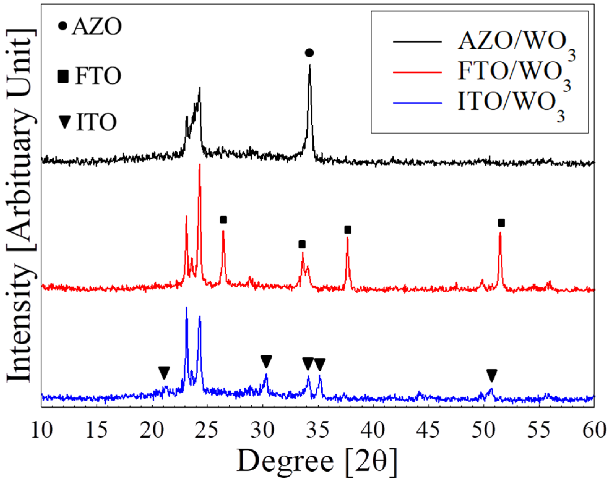
3.1. Structural Properties of WO3 Films with Various TCOs
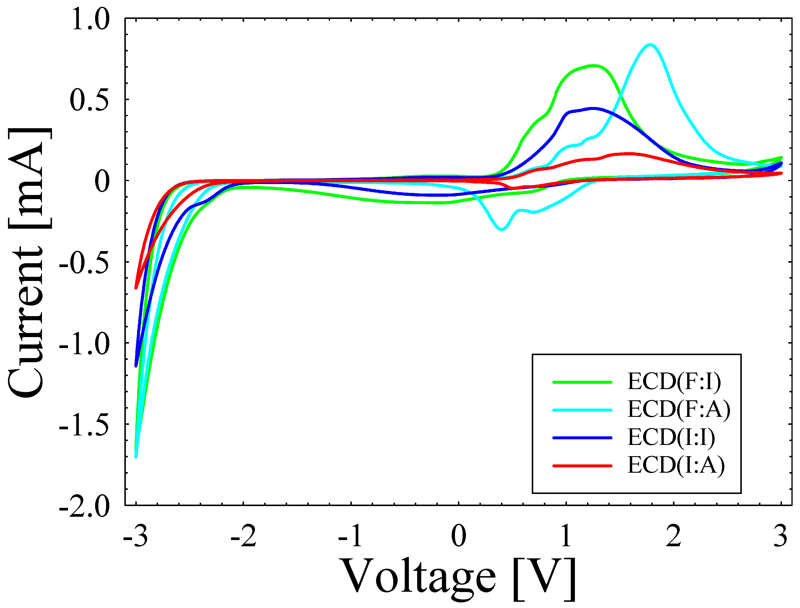
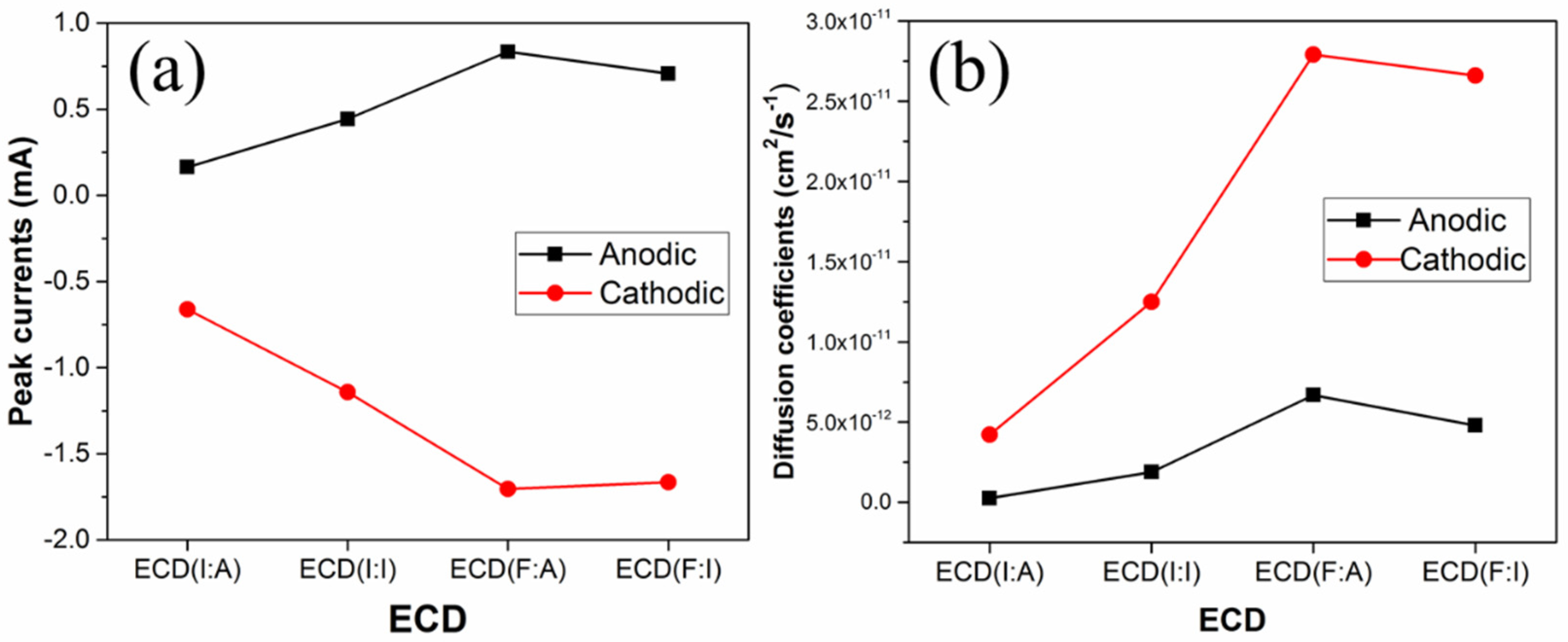
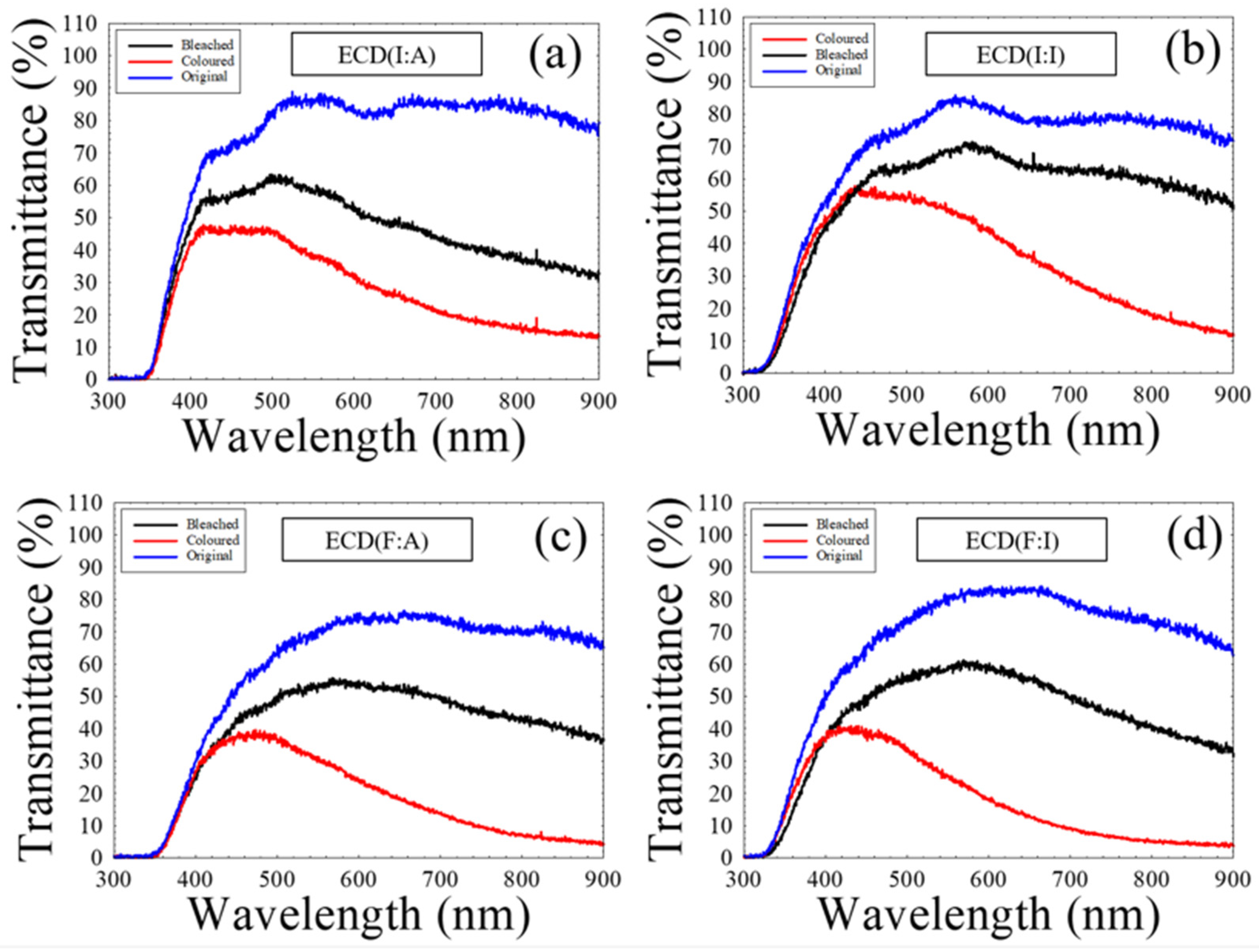
3.2. EC Performance of WO3-Based ECDs with Various TCOs
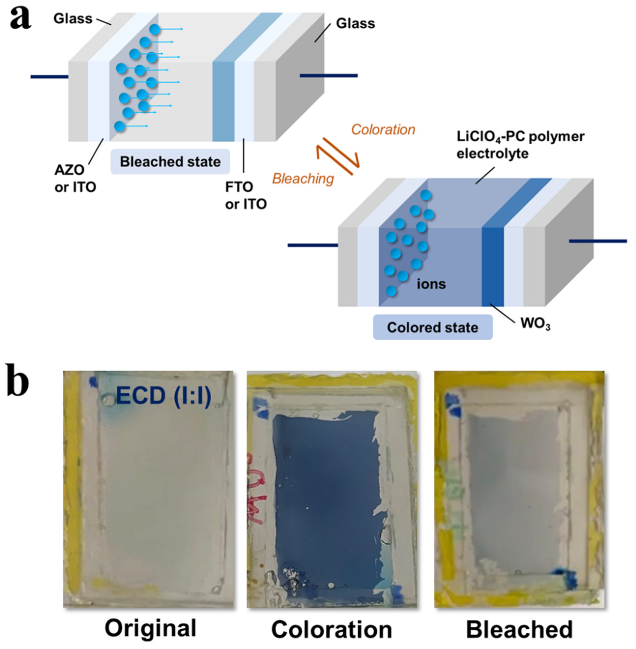
3.3. EC Mechanism of WO3-Based ECDs with Conducting Polymer Electrolyte
4. Conclusions
Author Contributions
Funding
Institutional Review Board Statement
Data Availability Statement
Acknowledgments
Conflicts of Interest
References
- Granqvist, C.G. Oxide Electrochromics: An Introduction to Devices and Materials. Sol. Energy Mater. Sol. Cells 2012, 99, 1–13. [Google Scholar] [CrossRef]
- Chu, C.H.; Wu, H.W.; Huang, J.L. Novel WO3-Based Electrochromic Device for High Optical Modulation and Infrared Suppression. IEEE Electron Device Lett. 2015, 36, 256–258. [Google Scholar] [CrossRef]
- Jung, D.; Choi, W.; Park, J.Y.; Kim, K.B.; Lee, N.; Seo, Y.; Kim, H.S.; Kong, N.K. Inorganic Gel and Liquid Crystal Based Smart Window Using Silica Sol-Gel Process. Sol. Energy Mater. Sol. Cells 2017, 159, 488–495. [Google Scholar] [CrossRef]
- Mane, A.T.; Kulkarni, S.B.; Navale, S.T.; Ghanwat, A.A.; Shinde, N.M.; Kim, J.; Patil, V.B. NO2 Sensing Properties of Nanostructured Tungsten Oxide Thin Films. Ceram. Int. 2014, 40, 16495–16502. [Google Scholar] [CrossRef]
- Qu, H.Y.; Rojas-González, E.A.; Granqvist, C.G.; Niklasson, G.A. Potentiostatically Pretreated Electrochromic Tungsten Oxide Films with Enhanced Durability: Electrochemical Processes at Interfaces of Indium–Tin Oxide. Thin Solid Film. 2019, 682, 163–168. [Google Scholar] [CrossRef]
- Dulgerbaki, C.; Komur, A.I.; Nohut Maslakci, N.; Kuralay, F.; Uygun Oksuz, A. Synergistic Tungsten Oxide/Organic Framework Hybrid Nanofibers for Electrochromic Device Application. Opt. Mater. 2017, 70, 171–179. [Google Scholar] [CrossRef]
- Karaca, G.Y.; Eren, E.; Cogal, G.C.; Uygun, E.; Oksuz, L.; Uygun Oksuz, A. Enhanced Electrochromic Characteristics Induced by Au/PEDOT/Pt Microtubes in WO3 Based Electrochromic Devices. Opt. Mater. 2019, 88, 472–478. [Google Scholar] [CrossRef]
- Liu, X.Y.; Yang, M.; Li, Q.; Pan, D. Research on the Properties of Sol-Gel Deposited WO3-NiO Thin Films. Key Eng. Mater. 2017, 727, 929. [Google Scholar] [CrossRef]
- Bhatnagar, M.; Kaushik, V.; Kaushal, A.; Singh, M.; Mehta, B.R. Structural and Photoluminescence Properties of Tin Oxide and Tin Oxide: C Core-Shell and Alloy Nanoparticles Synthesised Using Gas Phase Technique. AIP Adv. 2016, 6, 095321. [Google Scholar] [CrossRef] [Green Version]
- Wen-Cheun Au, B.; Chan, K.Y.; Knipp, D. Effect of Film Thickness on Electrochromic Performance of Sol-Gel Deposited Tungsten Oxide (WO3). Opt. Mater. 2019, 94, 387–392. [Google Scholar] [CrossRef]
- Khan, A.; Bhosale, N.Y.; Mali, S.S.; Hong, C.K.; Kadam, A. V Reduced Graphene Oxide Layered WO3 Thin Film with Enhanced Electrochromic Properties. J. Colloid Interface Sci. 2020, 571, 185–193. [Google Scholar] [CrossRef] [PubMed]
- Dulgerbaki, C.; Oksuz, A.U. Fabricating Polypyrrole/Tungsten Oxide Hybrid Based Electrochromic Devices Using Different Ionic Liquids. Polym. Adv. Technol. 2016, 27, 73–81. [Google Scholar] [CrossRef]
- Song, S.; Xu, G.; Wang, B.; Gu, J.; Wei, H.; Ren, Z.; Zhang, L.; Zhao, J.; Li, Y. Highly-Flexible Monolithic Integrated Infrared Electrochromic Device Based on Polyaniline Conducting Polymer. Synth. Met. 2021, 278, 116822. [Google Scholar] [CrossRef]
- Chaudhary, A.; Pathak, D.K.; Mishra, S.; Yogi, P.; Sagdeo, P.R.; Kumar, R. Polythiophene -Viologen Bilayer for Electro-Trichromic Device. Sol. Energy Mater. Sol. Cells 2018, 188, 249–254. [Google Scholar] [CrossRef]
- Sorar, I.; Bayrak Pehlivan, İ.; Bohlin, J.; Granqvist, C.G.; Niklasson, G.A. Potentiostatic Rejuvenation of Electrochromic WO3 Thin Films: Exploring the Effect of Polyethylene Oxide in LiClO4-Propylene Carbonate Electrolytes. Sol. Energy Mater. Sol. Cells 2020, 218, 110767. [Google Scholar] [CrossRef]
- Hou, X.F.; Zhang, S.; Chen, X.; Bisoyi, H.K.; Xu, T.; Liu, J.; Chen, D.; Chen, X.M.; Li, Q. Synchronous Imaging in Golgi Apparatus and Lysosome Enabled by Amphiphilic Calixarene-Based Artificial Light-Harvesting Systems. ACS Appl. Mater. Interfaces. 2022, 14, 22443. [Google Scholar] [CrossRef]
- Kalagi, S.S.; Mali, S.S.; Dalavi, D.S.; Inamdar, A.I.; Im, H.; Patil, P.S. Transmission Attenuation and Chromic Contrast Characterization of R.F. Sputtered WO3 Thin Films for Electrochromic Device Applications. Electrochim. Acta 2012, 85, 501–508. [Google Scholar] [CrossRef]
- Chananonnawathorn, C.; Pudwat, S.; Horprathum, M.; Eiamchai, P.; Limnontakul, P.; Salawan, C.; Aiempanakit, K. Electrochromic Property Dependent on Oxygen Gas Flow Rate and Films Thickness of Sputtered WO3 Films. Procedia Eng. 2012, 32, 752–758. [Google Scholar] [CrossRef] [Green Version]
- Cossari, P.; Cannavale, A.; Gambino, S.; Gigli, G. Room Temperature Processing for Solid-State Electrochromic Devices on Single Substrate: From Glass to Flexible Plastic. Sol. Energy Mater. Sol. Cells 2016, 155, 411–420. [Google Scholar] [CrossRef]
- Lethy, K.J.; Beena, D.; Vinod Kumar, R.; Mahadevan Pillai, V.P.; Ganesan, V.; Sathe, V.; Phase, D.M. Nanostructured Tungsten Oxide Thin Films by the Reactive Pulsed Laser Deposition Technique. Appl. Phys. A 2008, 91, 637–649. [Google Scholar] [CrossRef]
- Wen-Cheun Au, B.; Tamang, A.; Knipp, D.; Chan, K.Y. Post-Annealing Effect on the Electrochromic Properties of WO3 Films. Opt. Mater. (Amst). 2020, 108, 110426. [Google Scholar] [CrossRef]
- Cheng, W.; Moreno-Gonzalez, M.; Hu, K.; Krzyszkowski, C.; Dvorak, D.J.; Weekes, D.M.; Tam, B.; Berlinguette, C.P. Solution-Deposited Solid-State Electrochromic Windows. iScience 2018, 10, 80–86. [Google Scholar] [CrossRef] [PubMed] [Green Version]
- Caglar, Y.; Caglar, M.; Ilican, S.; Aksoy, S.; Yakuphanoglu, F. Effect of Channel Thickness on the Field Effect Mobility of ZnO-TFT Fabricated by Sol Gel Process. J. Alloys Compd. 2015, 621, 189–193. [Google Scholar] [CrossRef]
- Che, X.; Wu, Z.; Dong, G.; Diao, X.; Zhou, Y.; Guo, J.; Dong, D.; Wang, M. Properties of All-Thin-Film Glass/ITO/WO3:H/Ta2O5/NiOx/ITO Electrochromic Devices Prepared by Magnetron Sputtering. Thin Solid Film. 2018, 662, 6–12. [Google Scholar] [CrossRef]
- Wang, B.; Man, W.; Yu, H.; Li, Y.; Zheng, F. Fabrication of Mo-Doped WO3 Nanorod Arrays on FTO Substrate with Enhanced Electrochromic Properties. Materials 2018, 11, 1627. [Google Scholar] [CrossRef] [PubMed] [Green Version]
- Hussain, S.A.; Kadhim, R.O.; Tarrad, S.N. Structural and Optical Properties of Tin Oxide and Indium Doped SnO2 Thin Films Deposited by Thermal Evaporation Technique. J. Adv. Phys. 2016, 12, 4394–4399. [Google Scholar] [CrossRef]
- Au, B.W.C.; Chan, K.Y. Sodium and Potassium Doped P-Type ZnO Films by Sol-Gel Spin-Coating Technique. Appl. Phys. A Mater. Sci. Process. 2017, 123, 1–9. [Google Scholar] [CrossRef]
- Terohid, S.A.A.; Heidari, S.; Jafari, A.; Asgary, S. Effect of Growth Time on Structural, Morphological and Electrical Properties of Tungsten Oxide Nanowire. Appl. Phys. A 2018, 124, 567. [Google Scholar] [CrossRef] [Green Version]
- Graßmann, C.; Mann, M.; Van Langenhove, L.; Schwarz-Pfeiffer, A. Textile Based Electrochromic Cells Prepared with Pedot: Pss and Gelled Electrolyte. Sensors 2020, 20, 5691. [Google Scholar] [CrossRef]
- Parida, B.; Gil, Y.; Kim, H. Highly Transparent Conducting Indium Tin Oxide Thin Films Prepared by Radio Frequency Magnetron Sputtering and Thermal Annealing. J. Nanosci. Nanotechnol. 2018, 19, 1455–1462. [Google Scholar] [CrossRef]
- Lu, Y.; Wang, S.; Yang, M.; Xu, X.; Li, Q. Comparative Study of AZO and ITO Thin Film Sputtered at Different Temperatures and Their Application in Cu2ZnSnS4 Solar Cells. J. Mater. Sci. Mater. Electron. 2018, 29, 17525–17532. [Google Scholar] [CrossRef]
- Cho, J.M.; Kim, J.; Kim, H.; Kim, M.; Moon, S.J.; Jo, J.; Shin, W.S. ITO/AZO Double-Layered Transparent Conducting Oxide Films for Organic Photovoltaic Cells. Mol. Cryst. Liq. Cryst. 2014, 597, 1–7. [Google Scholar] [CrossRef]
- Kim, K.H.; Koo, B.R.; Ahn, H.J. Sheet Resistance Dependence of Fluorine-Doped Tin Oxide Films for High-Performance Electrochromic Devices. Ceram. Int. 2018, 44, 9408–9413. [Google Scholar] [CrossRef]
- Ching-Prado, E.; Watson, A.; Miranda, H. Optical and Electrical Properties of Fluorine Doped Tin Oxide Thin Film. J. Mater. Sci. Mater. Electron. 2018, 29, 15299–15306. [Google Scholar] [CrossRef]
- Mardare, C.C.; Hassel, A.W. Review on the Versatility of Tungsten Oxide Coatings. Phys. Status Solidi 2019, 216, 1900047. [Google Scholar] [CrossRef]


| ECD | Anodic Peak Current, mA | Cathodic Peak Current, mA | Anodic Diffusion Coefficient, cm2/s−1 | Cathodic Diffusion Coefficient, cm2/s−1 |
|---|---|---|---|---|
| ECD(I:A) | 0.164 | −0.662 | 2.59 × 10⁻¹³ | 4.21 × 10⁻¹² |
| ECD(I:I) | 0.443 | −1.142 | 1.89 × 10⁻¹² | 1.25 × 10⁻¹¹ |
| ECD(F:A) | 0.834 | −1.705 | 6.69 × 10⁻¹² | 2.79 × 10⁻¹¹ |
| ECD(F:I) | 0.706 | −1.665 | 4.79 × 10⁻¹² | 2.66 × 10⁻¹¹ |
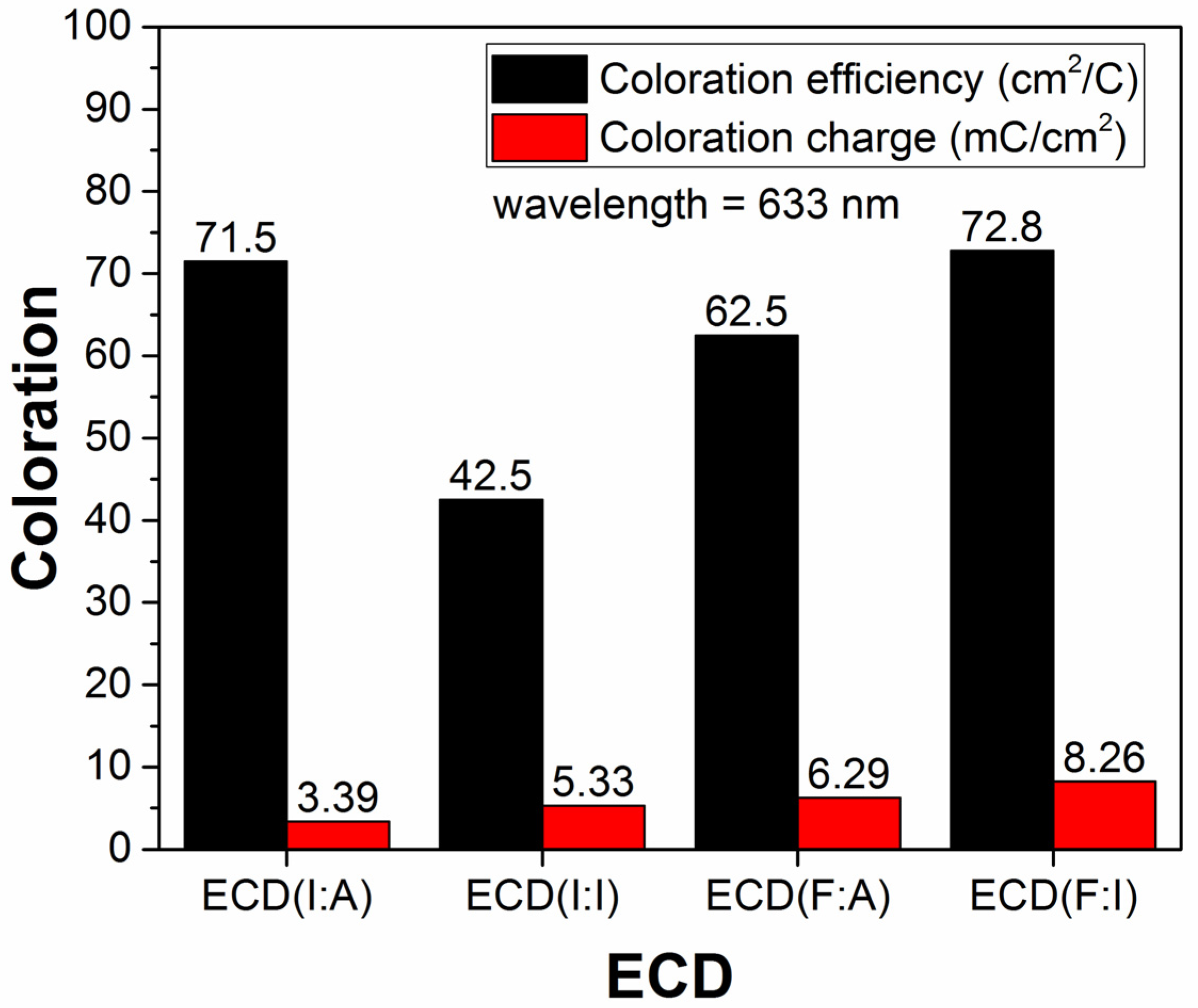
| ECD | Coloration Efficiency (cm2/C) | Coloration Charge (mC/cm2) |
|---|---|---|
| ECD(I:A) | 71.5 | 3.39 |
| ECD(I:I) | 42.5 | 5.33 |
| ECD(F:A) | 62.5 | 6.29 |
| ECD(F:I) | 72.8 | 8.26 |
Disclaimer/Publisher’s Note: The statements, opinions and data contained in all publications are solely those of the individual author(s) and contributor(s) and not of MDPI and/or the editor(s). MDPI and/or the editor(s) disclaim responsibility for any injury to people or property resulting from any ideas, methods, instructions or products referred to in the content. |
© 2023 by the authors. Licensee MDPI, Basel, Switzerland. This article is an open access article distributed under the terms and conditions of the Creative Commons Attribution (CC BY) license (https://creativecommons.org/licenses/by/4.0/).
Share and Cite
Au, B.W.-C.; Chan, K.-Y.; Thien, G.S.H.; Yeoh, M.-E.; Sahdan, M.Z.; Murthy, H.C.A. The Effect of Transparent Conducting Oxide Films on WO3-Based Electrochromic Devices with Conducting Polymer Electrolytes. Polymers 2023, 15, 238. https://doi.org/10.3390/polym15010238
Au BW-C, Chan K-Y, Thien GSH, Yeoh M-E, Sahdan MZ, Murthy HCA. The Effect of Transparent Conducting Oxide Films on WO3-Based Electrochromic Devices with Conducting Polymer Electrolytes. Polymers. 2023; 15(1):238. https://doi.org/10.3390/polym15010238
Chicago/Turabian StyleAu, Benedict Wen-Cheun, Kah-Yoong Chan, Gregory Soon How Thien, Mian-En Yeoh, Mohd Zainizan Sahdan, and Hanabe Chowdappa Ananda Murthy. 2023. "The Effect of Transparent Conducting Oxide Films on WO3-Based Electrochromic Devices with Conducting Polymer Electrolytes" Polymers 15, no. 1: 238. https://doi.org/10.3390/polym15010238