
PCL/Collagen/UA Composite Biomedical Dressing with Ordered Microfiberous Structure Fabricated by a 3D Near-Field Electrospinning Process

Abstract
:1. Introduction
2. Experimental Section
2.1. Materials Required
2.2. Experimental Methods
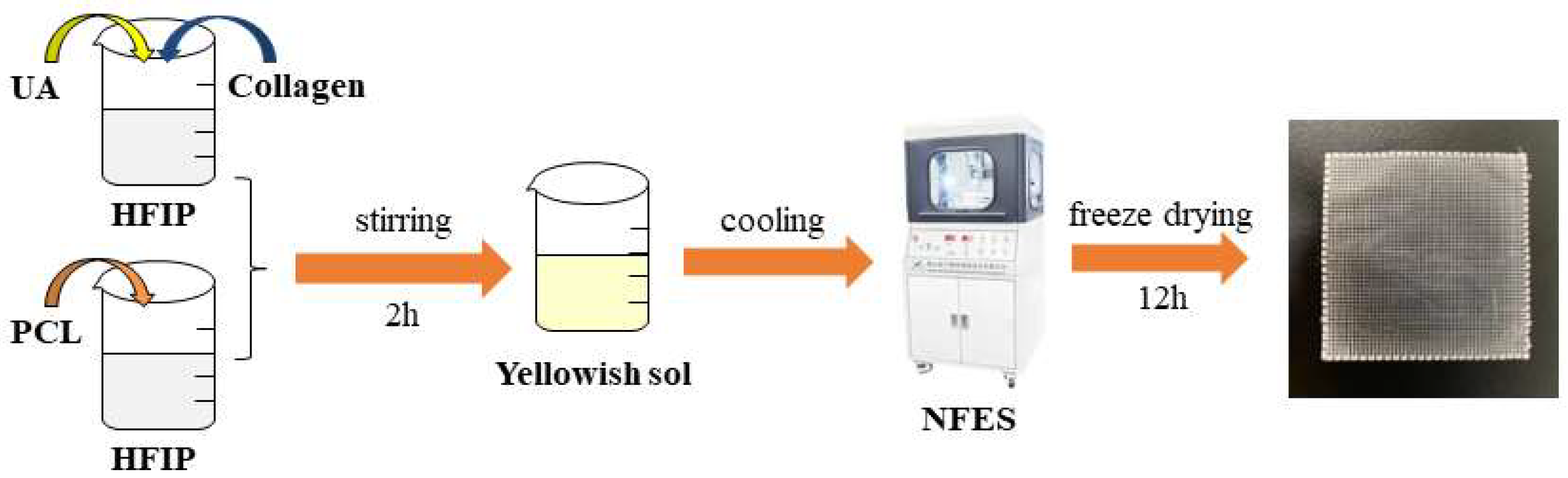
2.2.1. Preparation and Electrospinning Process of PCL-Ordered Microfibers
2.2.2. Preparation of PCL/CO/UA-Ordered Composite Microfibers
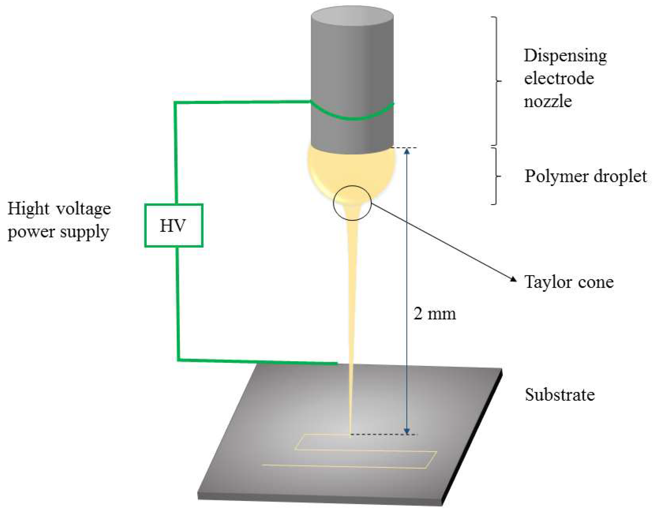
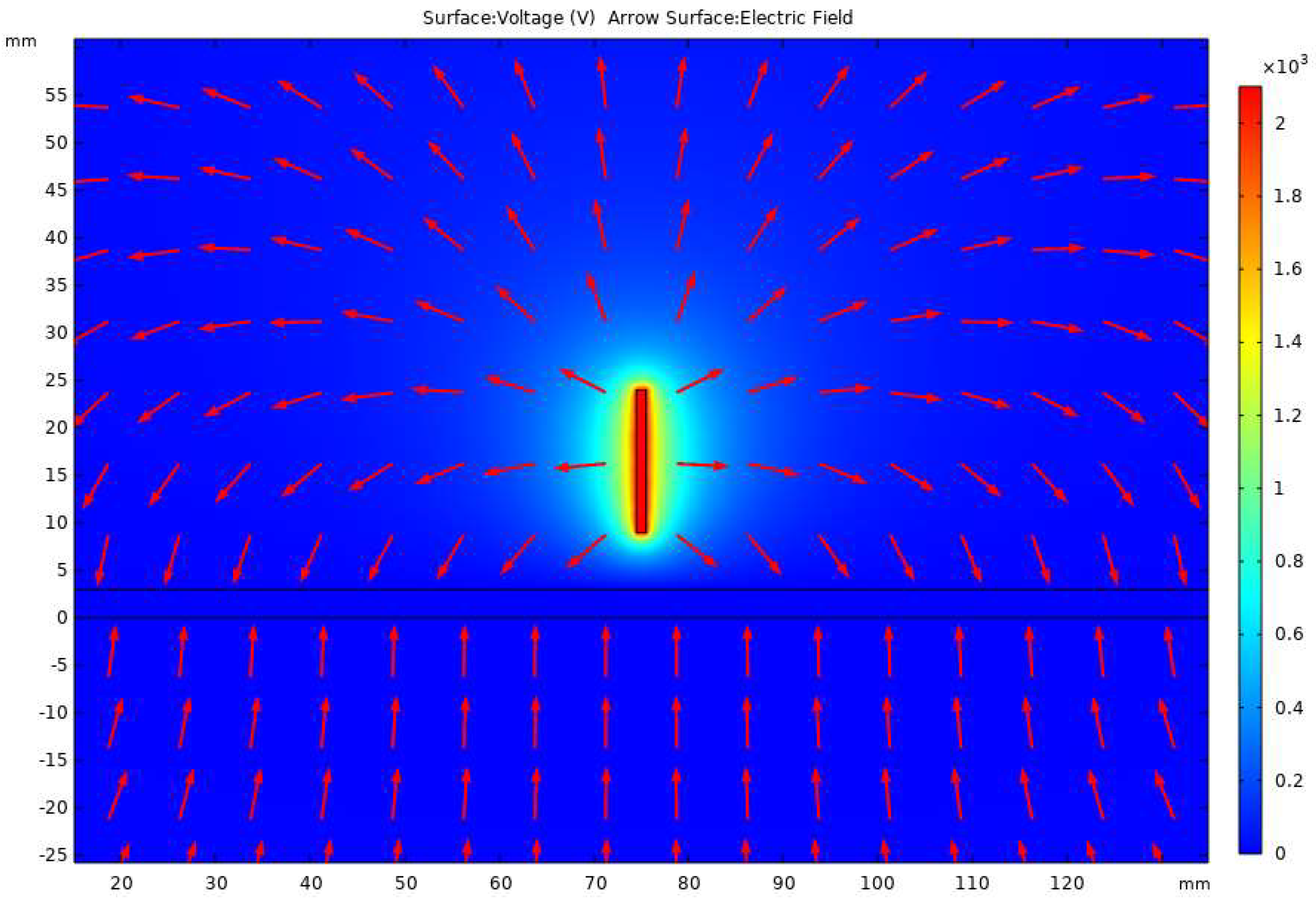
2.2.3. Simulation of Electrostatic Field in near Field Electrospinning
2.2.4. Preparation of Collagen Crosslinking and Composite Electrospinning Fiber after Crosslinking
2.3. Characterization
2.3.1. FTIR Analysis
2.3.2. SEM Analysis
2.3.3. Mechanical Property Test
2.3.4. Antibacterial Performance Test
2.3.5. Hydrophilic and Water Absorption Performance Test
2.3.6. Determination of Drug-Sustained Release Performance In Vitro
2.3.7. XRD Analysis
2.3.8. Thermal Performance Analysis
2.3.9. Cell Proliferation Test In Vitro
3. Results and Discussion
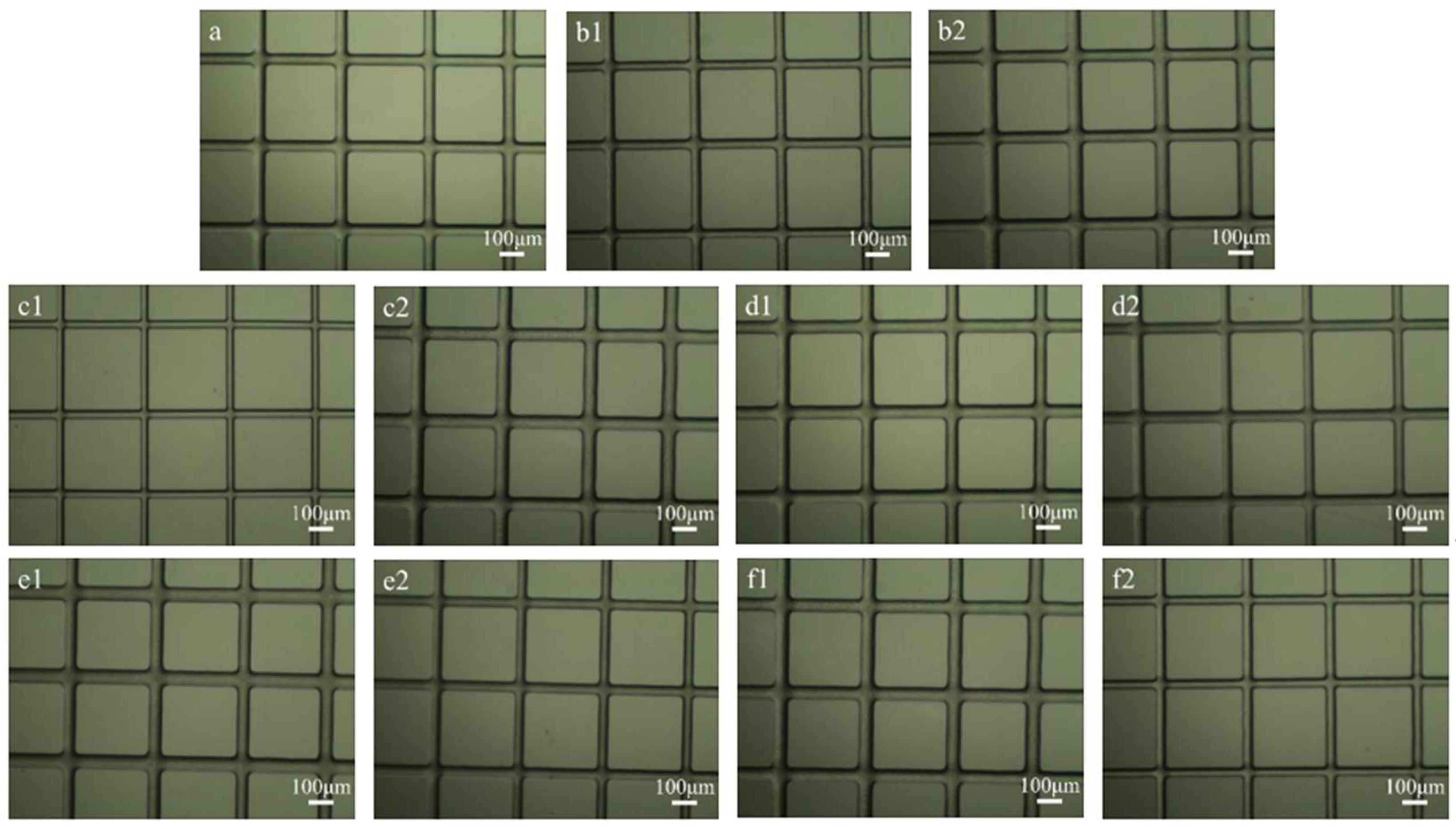
3.1. Preparation and Electrospinning Process of PCL-Ordered Microfibers
3.2. Electrostatic Field Simulation of NFES
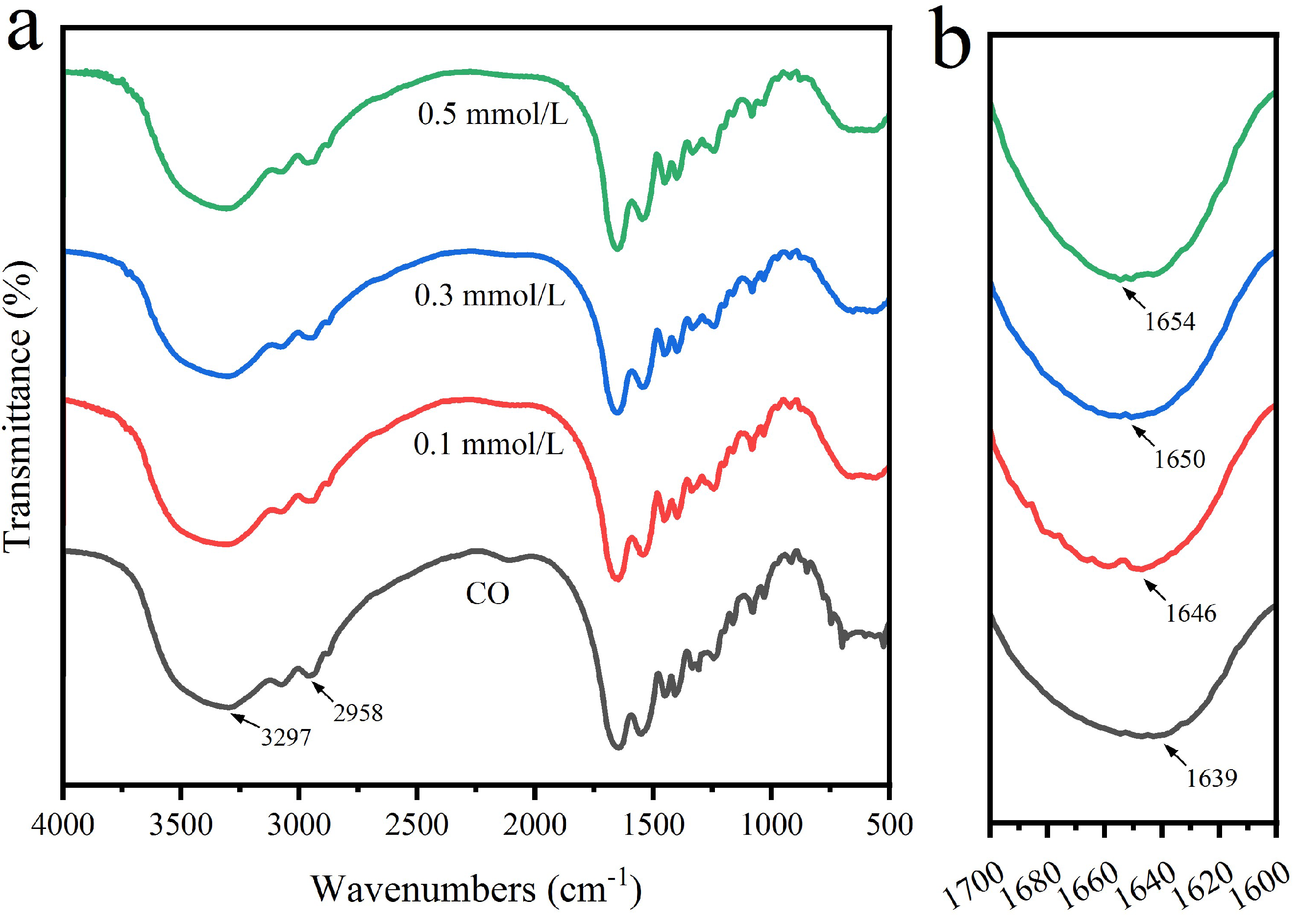
3.3. FTIR Analysis
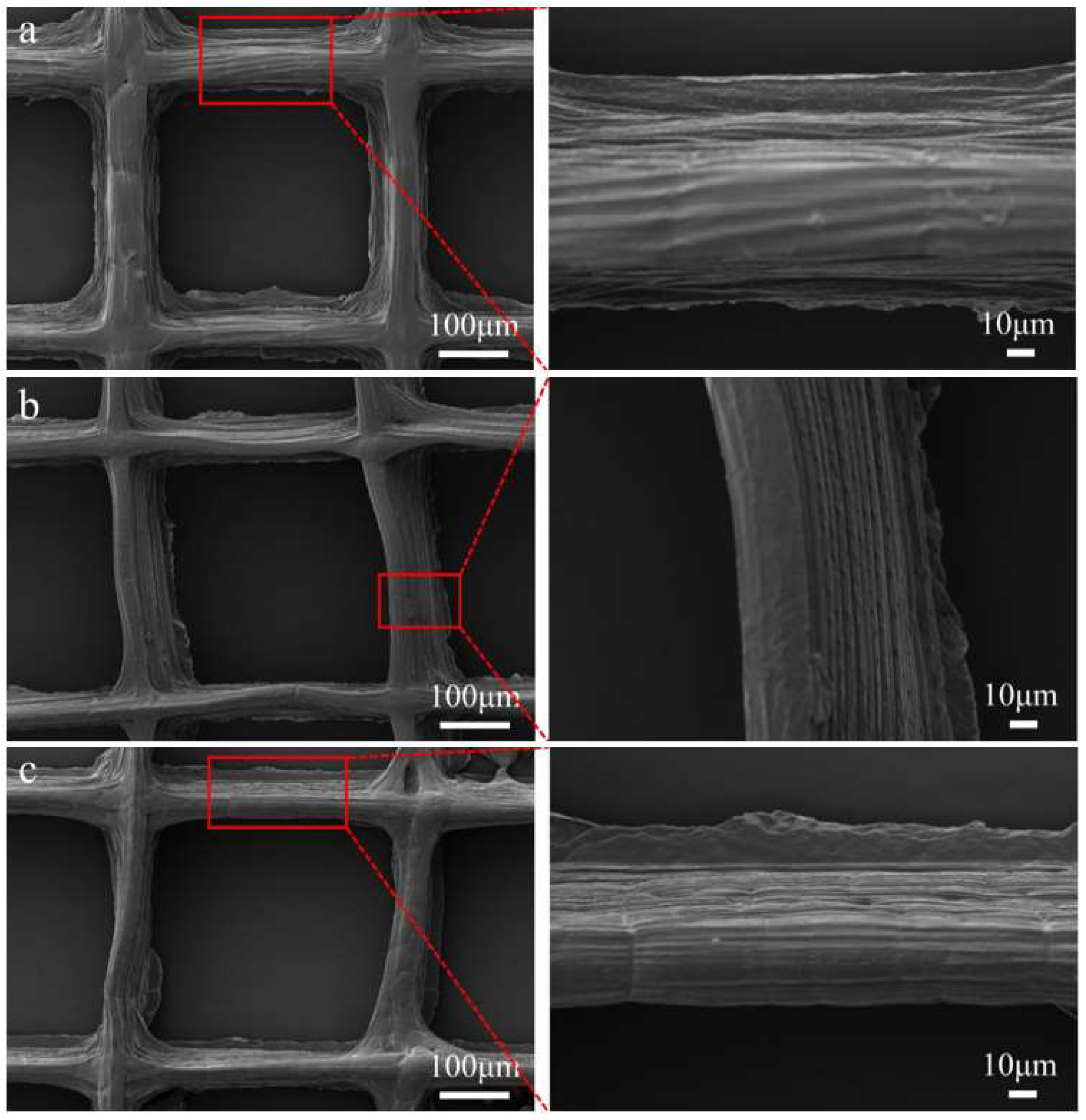
3.4. SEM Analysis
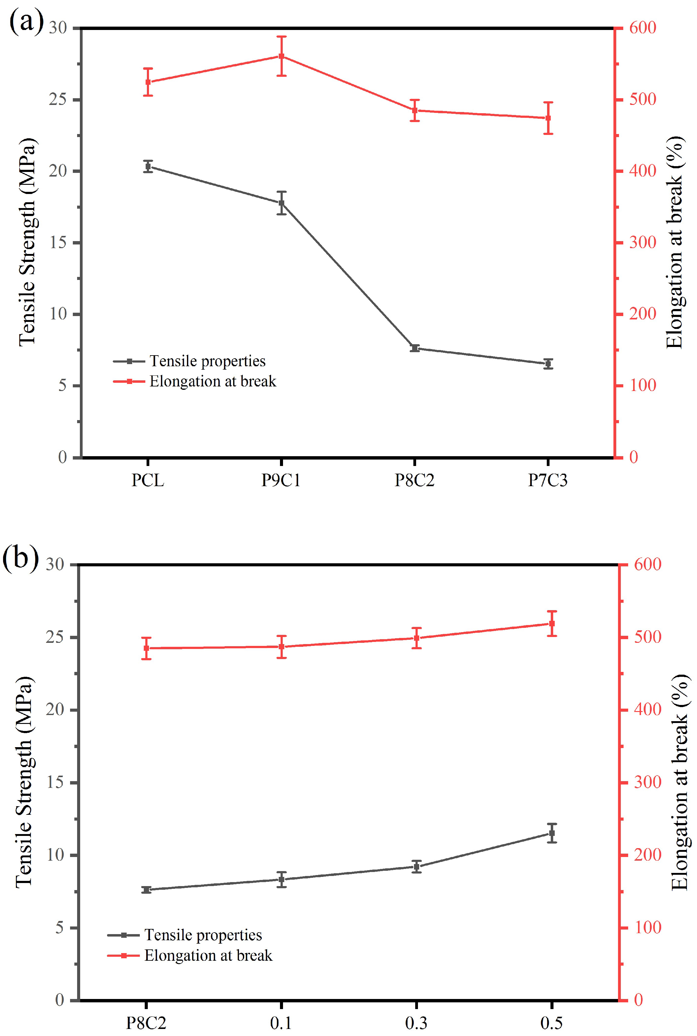
3.5. Mechanical Property Test
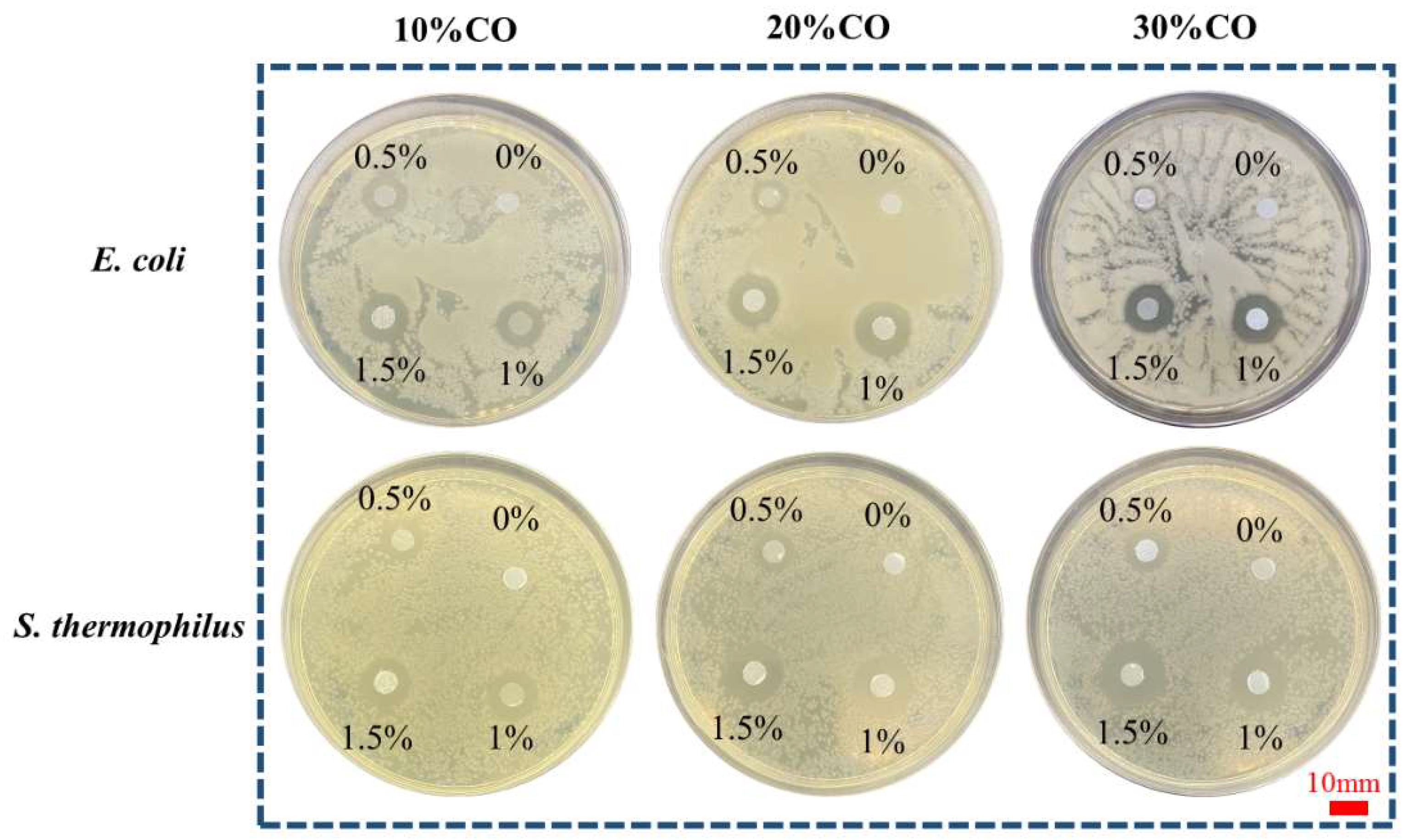
3.6. Antibacterial Performance Test
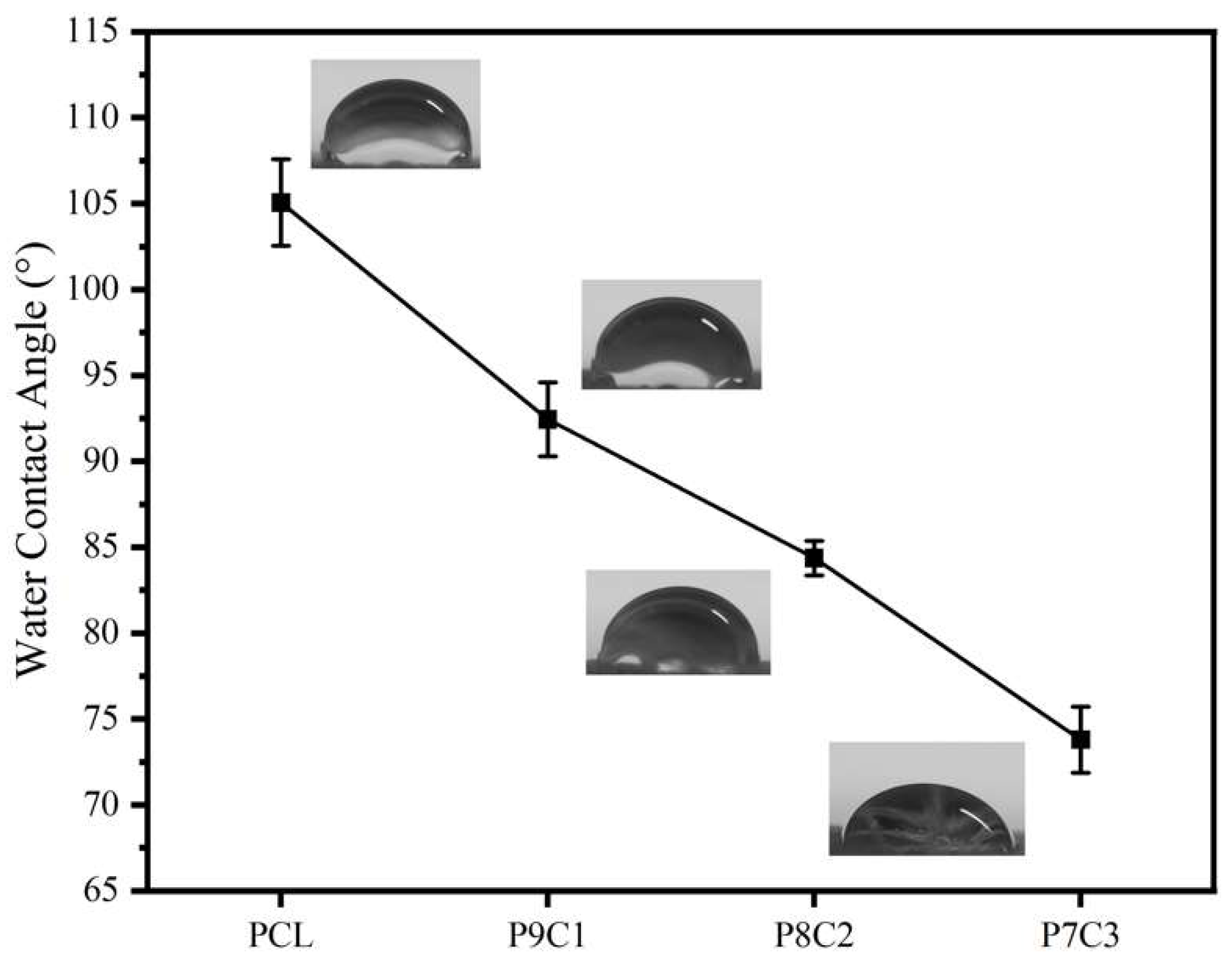
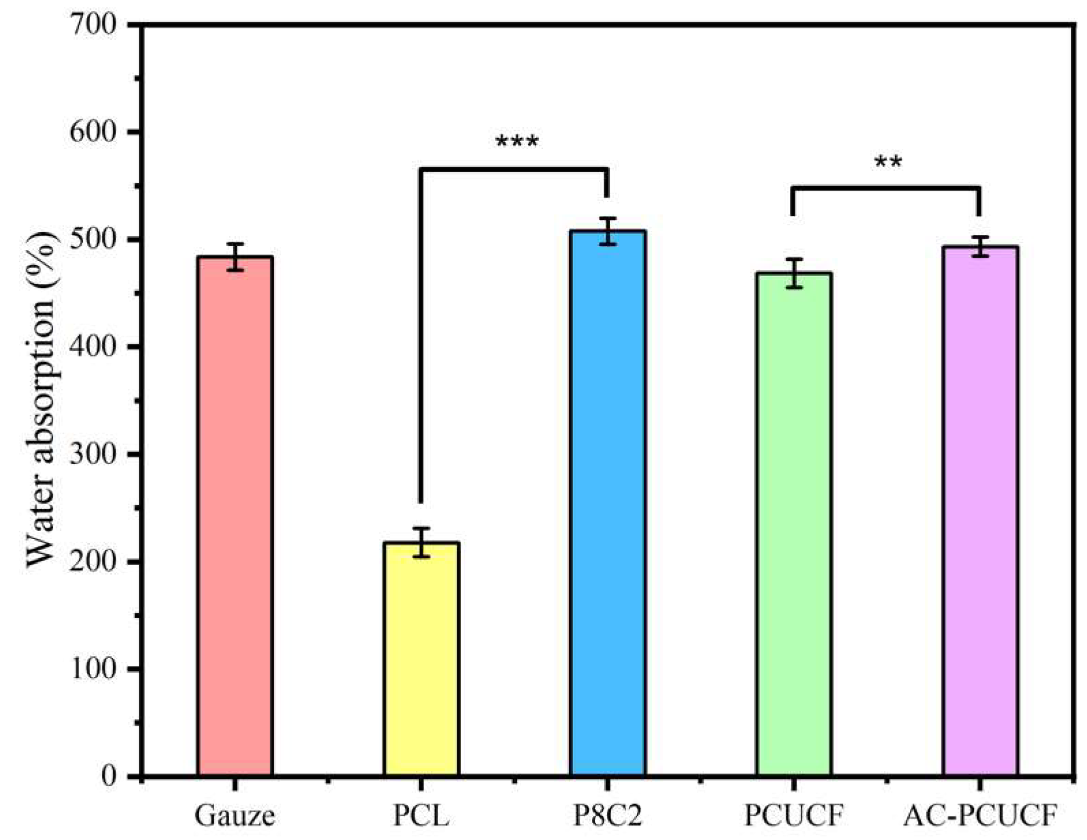
3.7. Hydrophilic and Water Absorption Performance Test
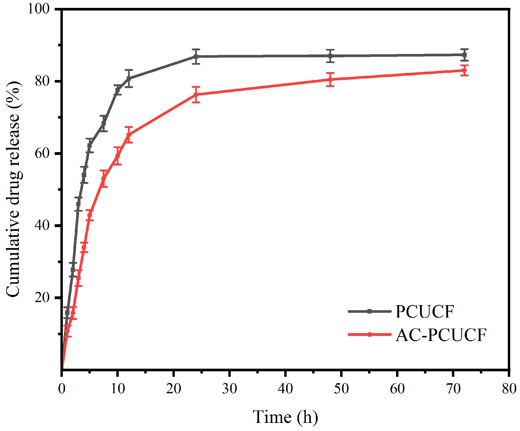
3.8. Determination of Drug Sustained Release Performance In Vitro
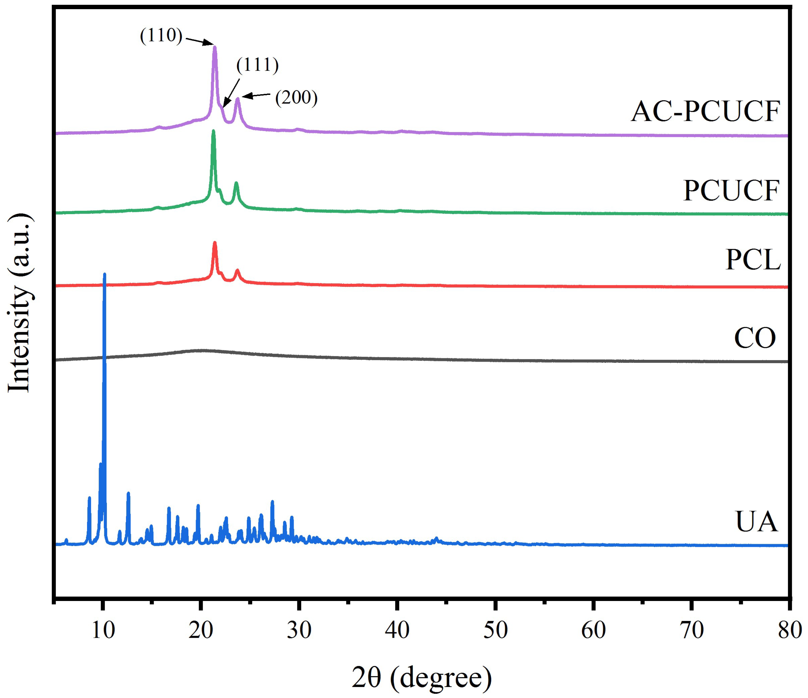
3.9. XRD Analysis
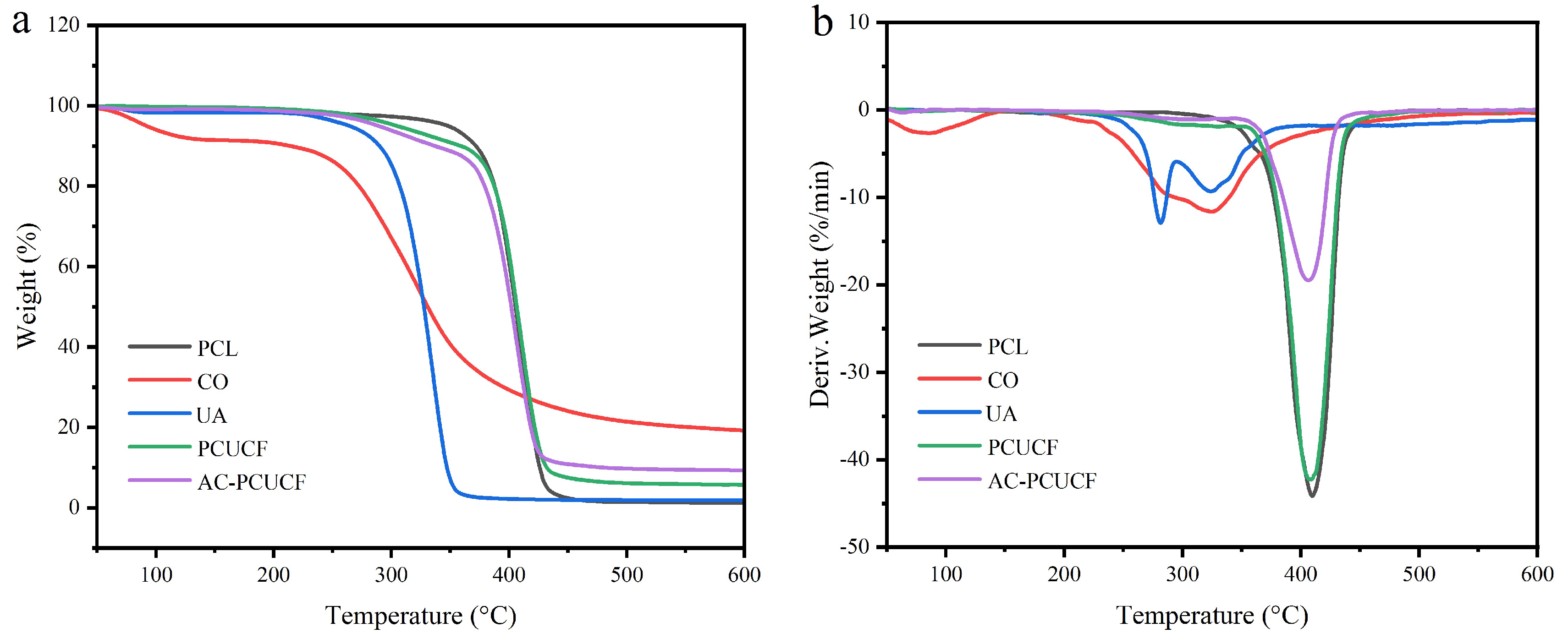
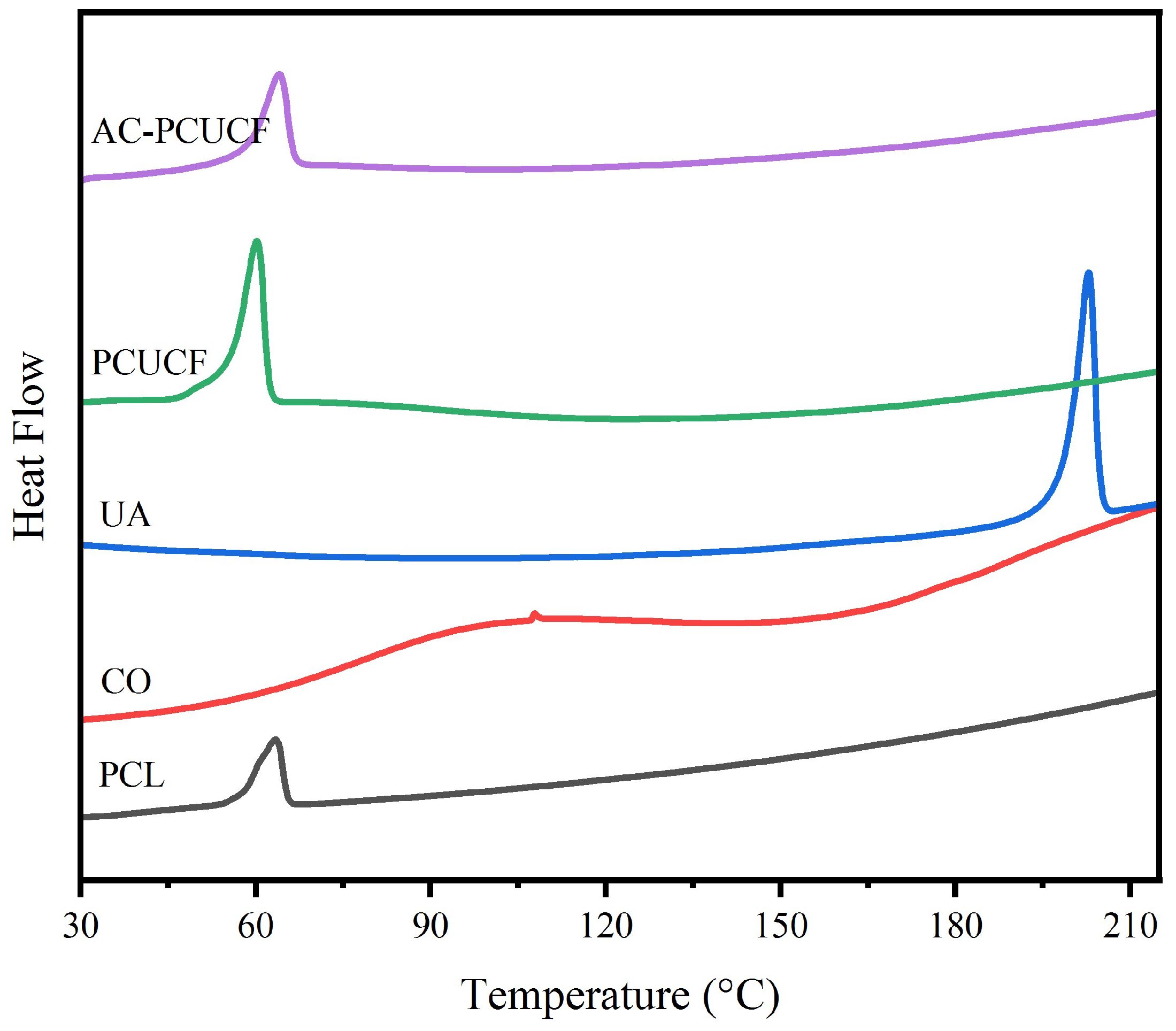
3.10. Thermal Performance Analysis
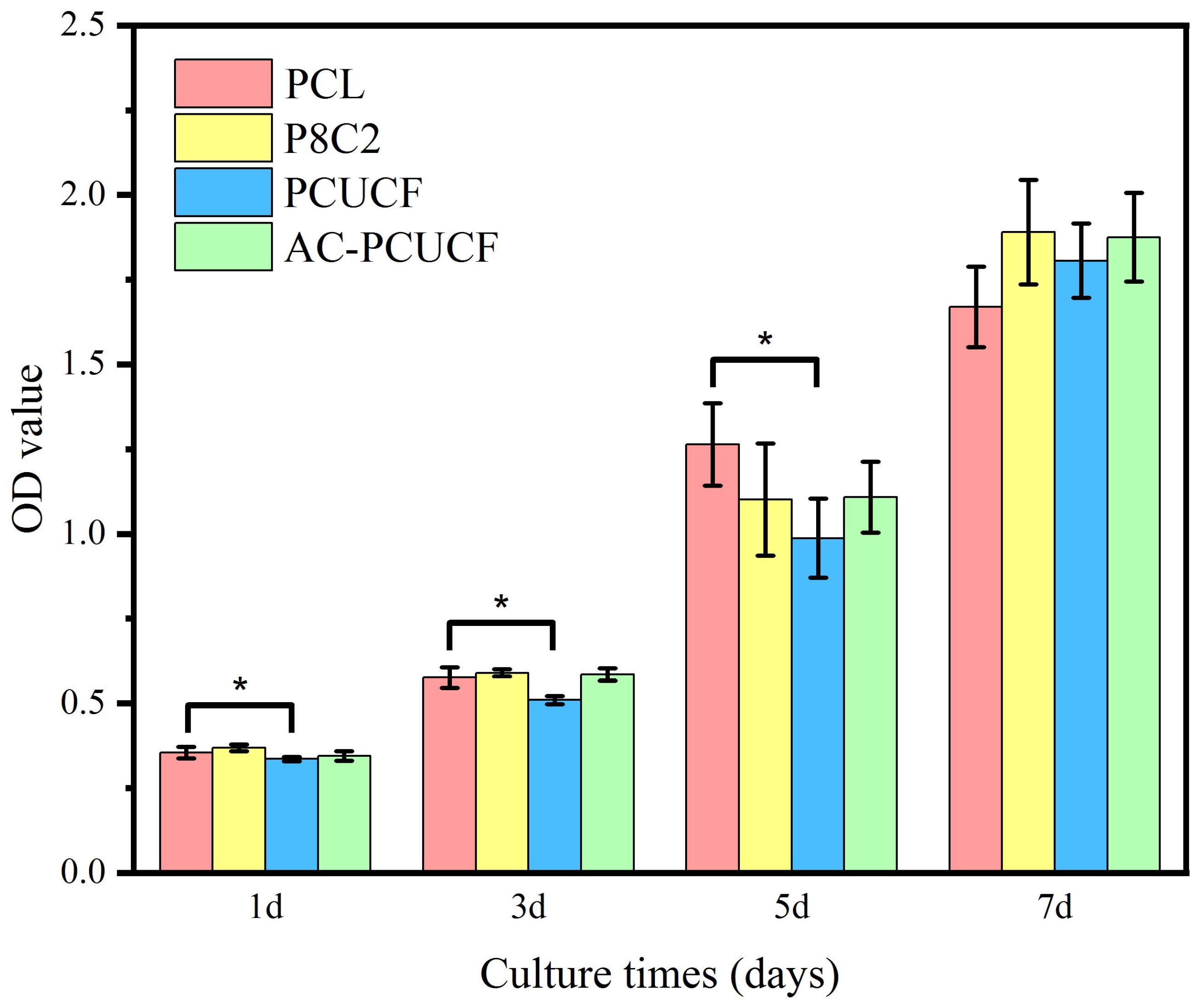
3.11. Cell Proliferation Test In Vitro
4. Conclusions
Author Contributions
Funding
Institutional Review Board Statement
Data Availability Statement
Conflicts of Interest
References
- Bozkurt, Y.; Karayel, E. 3D printing technology; methods, biomedical applications, future opportunities and trends. J. Mater. Res. Technol. 2021, 14, 1430–1450. [Google Scholar] [CrossRef]
- Wang, W.; Zhang, B.; Li, M.; Li, J.; Zhang, C.; Han, Y.; Wang, L.; Wang, K.; Zhou, C.; Liu, L.; et al. 3D printing of PLA/N-Ha composite scaffolds with customized mechanical properties and biological functions for bone tissue engineering. Compos. Part B Eng. 2021, 224, 109192. [Google Scholar] [CrossRef]
- Wu, X.; Liu, S.; Chen, K.; Wang, F.; Feng, C.; Xu, L.; Zhang, D. 3D printed chitosan-gelatine hydrogel coating on titanium alloy surface as biological fixation interface of artificial joint prosthesis. Int. J. Biol. Macromol. 2021, 182, 669–679. [Google Scholar] [CrossRef] [PubMed]
- Ding, J.; Zhang, J.; Li, J.; Li, D.; Xiao, C.; Xiao, H.; Yang, H.; Zhuang, X.; Chen, X. Electrospun polymer biomaterials. Prog. Polym. Sci. 2019, 90, 1–34. [Google Scholar] [CrossRef]
- Kamoun, E.A.; Loutfy, S.A.; Hussein, Y.; Kenawy, E.S. Recent advances in pva-polysaccharide based hydrogels and electrospun nanofibers in biomedical applications: A review. Int. J. Biol. Macromol. 2021, 187, 755–768. [Google Scholar] [CrossRef]
- Xu, L.; Liu, Y.; Zhou, W.; Yu, D. Electrospun medical sutures for wound healing: A review. Polymers 2022, 14, 1637. [Google Scholar] [CrossRef]
- Yan, X.; Yu, M.; Ramakrishna, S.; Russell, S.J.; Long, Y. Advances in portable electrospinning devices for in situ delivery of personalized wound care. Nanoscale 2019, 11, 19166–19178. [Google Scholar] [CrossRef]
- Afsharian, Y.P.; Rahimnejad, M. Bioactive electrospun scaffolds for wound healing applications: A comprehensive review. Polym. Test. 2021, 93, 106952. [Google Scholar] [CrossRef]
- Li, J.; Liu, Y.; Abdelhakim, H. Drug delivery applications of coaxial electrospun nanofibres in cancer therapy. Molecules 2022, 27, 1803. [Google Scholar] [CrossRef]
- Serrano-Garcia, W.; Ramakrishna, S.; Thomas, S.W. Electrospinning technique for fabrication of coaxial nanofibers of semiconductive polymers. Polymers 2022, 14, 5073. [Google Scholar] [CrossRef]
- Hou, Z.; Itagaki, N.; Kobayashi, H.; Tanaka, K.; Takarada, W.; Kikutani, T.; Takasaki, M. Bamboo charcoal/poly(l-lactide) fiber webs prepared using laser-heated melt electrospinning. Polymers 2021, 13, 2776. [Google Scholar] [CrossRef] [PubMed]
- Zhong, H.; Huang, J.; Luo, M.; Fang, Y.; Zeng, X.; Wu, J.; Du, J. Near-field electrospun PCL fibers/gelma hydrogel composite dressing with controlled deferoxamine-release ability and retiform surface for diabetic wound healing. Nano Res. 2022, 1–14. [Google Scholar] [CrossRef]
- Eghbalifam, N.; Shojaosadati, S.A.; Hashemi-Najafabadi, S.; Khorasani, A.C. Synthesis and characterization of antimicrobial wound dressing material based on silver nanoparticles loaded gum arabic nanofibers. Int. J. Biol. Macromol. 2020, 155, 119–130. [Google Scholar] [CrossRef] [PubMed]
- Gao, C.; Zhang, L.; Wang, J.; Jin, M.; Tang, Q.; Chen, Z.; Cheng, Y.; Yang, R.; Zhao, G. Electrospun nanofibers promote wound healing: Theories, techniques, and perspectives. J. Mat. Chem. B. 2021, 9, 3106–3130. [Google Scholar] [CrossRef]
- Rezvani Ghomi, E.; Nourbakhsh, N.; Akbari Kenari, M.; Zare, M.; Ramakrishna, S. Collagen-based biomaterials for biomedical applications. J. Biomed. Mater. Res. Part B 2021, 109, 1986–1999. [Google Scholar] [CrossRef] [PubMed]
- Irastorza, A.; Zarandona, I.; Andonegi, M.; Guerrero, P.; de la Caba, K. The versatility of collagen and chitosan: From food to biomedical applications. Food Hydrocolloids. 2021, 116, 106633. [Google Scholar] [CrossRef]
- Jiménez Vázquez, J.; San Martín Martínez, E. Collagen and elastin scaffold by electrospinning for skin tissue engineering applications. J. Mater. Res. 2019, 34, 2819–2827. [Google Scholar] [CrossRef]
- Sorushanova, A.; Delgado, L.M.; Wu, Z.; Shologu, N.; Kshirsagar, A.; Raghunath, R.; Mullen, A.M.; Bayon, Y.; Pandit, A.; Raghunath, M.; et al. The collagen suprafamily: From biosynthesis to advanced biomaterial development. Adv. Mater. 2019, 3, 1801651. [Google Scholar] [CrossRef] [Green Version]
- Bhovi, V.K.; Melinmath, S.P.; Gowda, R. Biodegradable polymers and their applications: A review. Mini Rev. Med. Chem. 2022, 22, 2081–2101. [Google Scholar] [CrossRef]
- Wu, J.; Hu, T.; Wang, H.; Zong, M.; Wu, H.; Wen, P. Electrospinning of PLA nanofibers: Recent advances and its potential application for food packaging. J. Agric. Food Chem. 2022, 70, 8207–8221. [Google Scholar] [CrossRef]
- Mochane, M.J.; Motsoeneng, T.S.; Sadiku, E.R.; Mokhena, T.C.; Sefadi, J.S. Morphology and properties of electrospun PCL and its composites for medical applications: A mini review. Appl. Sci. 2019, 9, 2205. [Google Scholar] [CrossRef] [Green Version]
- Banikazemi, S.; Rezaei, M.; Rezaei, P.; Babaie, A.; Eyvazzadeh Kalajahi, A. Preparation of electrospun shape memory polyurethane fibers in optimized electrospinning conditions via response surface methodology. Polym. Adv. Technol. 2020, 31, 2199–2208. [Google Scholar] [CrossRef]
- Kotcharat, P.; Chuysinuan, P.; Thanyacharoen, T.; Techasakul, S.; Ummartyotin, S. Development of bacterial cellulose and polycaprolactone (PCL) based composite for medical material. Sustain. Chem. Pharm. 2021, 20, 100404. [Google Scholar] [CrossRef]
- Herrero-Herrero, M.; Alberdi-Torres, S.; González-Fernández, M.L.; Vilariño-Feltrer, G.; Rodríguez-Hernández, J.C.; Vallés-Lluch, A.; Villar-Suárez, V. Influence of chemistry and fiber diameter of electrospun PLA, PCL and their blend membranes, intended as cell supports, on their biological behavior. Polym. Test. 2021, 103, 107364. [Google Scholar] [CrossRef]
- Zhao, L.; Li, X.; Yang, L.; Sun, L.; Mu, S.; Zong, H.; Li, Q.; Wang, F.; Song, S.; Yang, C.; et al. Evaluation of remodeling and regeneration of electrospun pcl/fibrin vascular grafts in vivo. Mater. Sci. Eng. C 2021, 118, 111441. [Google Scholar] [CrossRef]
- Wang, H.; Xuan, M.; Huang, C.; Wang, C. Advances in research on bioactivity, toxicity, metabolism, and pharmacokinetics of usnic acid in vitro and in vivo. Molecules 2022, 27, 7469. [Google Scholar] [CrossRef]
- Macedo, D.C.S.; Almeida, F.J.F.; Wanderley, M.S.O.; Ferraz, M.S.; Santos, N.P.S.; López, A.M.Q.; Santos-Magalhães, N.S.; Lira-Nogueira, M.C.B. Usnic acid: From an ancient lichen derivative to promising biological and nanotechnology applications. Phytochem. Rev. 2021, 20, 609–630. [Google Scholar] [CrossRef]
- Chandika, P.; Khan, F.; Heo, S.; Kim, Y.; Yi, M.; Jung, W. Enhanced wound-healing capability with inherent antimicrobial activities of usnic acid incorporated poly(ε-caprolactone)/decellularized extracellular matrix nanofibrous scaffold. Bio. Adv. 2022, 140, 213046. [Google Scholar] [CrossRef]
- Coskunmeric, N.; Ustundag, O.N.; Okur, M.E.; Ayla, S.; Yoltas, A.; Karavana, S.Y. Promising nanogels loaded with usnic acid for oral ulcer treatment: Development, characterization, and in vivo evaluation in rabbits. Pharm. Dev. Technol. 2021, 26, 431–443. [Google Scholar] [CrossRef]
- Pintas, S.K.; Quave, C.L. A review of botanicals exhibiting antifungal activity against malassezia spp. Implicated in common skin conditions. Curr. Dermatol. Rep. 2019, 8, 279–296. [Google Scholar] [CrossRef]
- Nikolin, V.P.; Popova, N.A.; Kaledin, V.I.; Luzina, O.A.; Zakharenko, A.L.; Salakhutdinov, N.F.; Lavrik, O.I. The influence of an enamine usnic acid derivative (a tyrosyl-DNA phosphodiesterase 1 inhibitor) on the therapeutic effect of topotecan against transplanted tumors in vivo. Clin. Exp. Metastasis. 2021, 38, 431–440. [Google Scholar] [CrossRef] [PubMed]
- Dos, S.M.; Alcaraz-Espinoza, J.J.; Da, C.M.; de Oliveira, H.P. Usnic acid-loaded polyaniline/polyurethane foam wound dressing: Preparation and bactericidal activity. Mater. Sci. Eng. C 2018, 89, 33–40. [Google Scholar]
- Zha, X.; Xiong, X.; Chen, C.; Li, Y.; Zhang, L.; Xie, H.; Jiang, Q. Usnic-acid-functionalized silk fibroin composite scaffolds for cutaneous wounds healing. Macromol. Biosci. 2021, 21, 2000361. [Google Scholar] [CrossRef] [PubMed]
- Nunes, P.S.; Albuquerque, R.J.; Cavalcante, D.R.; Dantas, M.D.; Cardoso, J.C.; Bezerra, M.S.; Souza, J.C.; Serafini, M.R.; Quitans, L.J.; Bonjardim, L.R.; et al. Collagen-based films containing liposome-loaded usnic acid as dressing for dermal burn healing. J. Biomed. Biotechnol. 2011, 2011, 761593. [Google Scholar] [CrossRef] [PubMed] [Green Version]
- Xu, T.; Binder, K.W.; Albanna, M.Z.; Dice, D.; Zhao, W.; Yoo, J.J.; Atala, A. Hybrid printing of mechanically and biologically improved constructs for cartilage tissue engineering applications. Biofabrication 2012, 5, 015001. [Google Scholar] [CrossRef]
- Liu, Y.; Yu, H.; Liu, Y.; Liang, G.; Zhang, T.; Hu, Q. Dual drug spatiotemporal release from functional gradient scaffolds prepared using 3d bioprinting and electrospinning. Polym. Eng. Sci. 2016, 56, 170–177. [Google Scholar] [CrossRef]
- King, W.; Bowlin, G. Near-field electrospinning and melt electrowriting of biomedical polymers—Progress and limitations. Polymers 2021, 13, 1097. [Google Scholar] [CrossRef]
- Yu, Y.; Xu, S.; Li, S.; Pan, H. Genipin-cross-linked hydrogels based on biomaterials for drug delivery: A review. Biomater. Sci. 2021, 9, 1583–1597. [Google Scholar] [CrossRef]
- Feng, X.; Dai, H.; Ma, L.; Yu, Y.; Tang, M.; Li, Y.; Hu, W.; Liu, T.; Zhang, Y. Food-grade gelatin nanoparticles: Preparation, characterization, and preliminary application for stabilizing pickering emulsions. Foods 2019, 8, 479. [Google Scholar] [CrossRef] [Green Version]
- Nezhad-Mokhtari, P.; Akrami-Hasan-Kohal, M.; Ghorbani, M. An injectable chitosan-based hydrogel scaffold containing gold nanoparticles for tissue engineering applications. Int. J. Biol. Macromol. 2020, 154, 198–205. [Google Scholar] [CrossRef]
- Xiong, Z.; Liu, W.; Qian, H.; Lei, T.; He, X.; Hu, Y.; Lei, P. Tantalum nanoparticles reinforced pcl scaffolds using direct 3d printing for bone tissue engineering. Front. Mater. 2021, 8, 609779. [Google Scholar] [CrossRef]
- Zhou, X.; Tao, Y.; Chen, E.; Wang, J.; Fang, W.; Zhao, T.; Liang, C.; Li, F.; Chen, Q. Genipin-cross-linked type II collagen scaffold promotes the differentiation of adipose-derived stem cells into nucleus pulposus-like cells. J. Biomed. Mater. Res. Part A 2018, 106, 1258–1268. [Google Scholar] [CrossRef] [PubMed]
- Wu, X.; Liu, Y.; Liu, A.; Wang, W. Improved thermal-stability and mechanical properties of type I collagen by crosslinking with casein, keratin and soy protein isolate using transglutaminase. Int. J. Biol. Macromol. 2017, 98, 292–301. [Google Scholar] [CrossRef] [PubMed]


| Samples (Figures) | wt (%) | Flow Rate (mL/h) | Applied Voltage (kV) | Distance (mm) | Moving Speed (mm/s) | Diameter (μm) |
|---|---|---|---|---|---|---|
| a | 18 | 0.4 | 2.1 | 2 | 150 | 53.4 ± 1.6 |
| b1 | 16 | 0.4 | 2.1 | 2 | 150 | 50.1 ± 1.6 |
| b2 | 20 | 0.4 | 2.1 | 2 | 150 | 64.7 ± 5.5 |
| c1 | 18 | 0.2 | 2.1 | 2 | 150 | 34.8 ± 2.2 |
| c2 | 18 | 0.6 | 2.1 | 2 | 150 | 63.9 ± 3.9 |
| d1 | 18 | 0.4 | 2.1 | 2 | 120 | 61.9 ± 1.6 |
| d2 | 18 | 0.4 | 2.1 | 2 | 180 | 51.4 ± 1.5 |
| e1 | 18 | 0.4 | 1.7 | 2 | 150 | 63.2 ± 2.2 |
| e2 | 18 | 0.4 | 2.5 | 2 | 150 | 48.8 ± 1.4 |
| f1 | 18 | 0.4 | 2.1 | 1 | 150 | 68.5 ± 2.0 |
| f2 | 18 | 0.4 | 2.1 | 3 | 150 | 46.2 ± 2.4 |
Disclaimer/Publisher’s Note: The statements, opinions and data contained in all publications are solely those of the individual author(s) and contributor(s) and not of MDPI and/or the editor(s). MDPI and/or the editor(s) disclaim responsibility for any injury to people or property resulting from any ideas, methods, instructions or products referred to in the content. |
© 2022 by the authors. Licensee MDPI, Basel, Switzerland. This article is an open access article distributed under the terms and conditions of the Creative Commons Attribution (CC BY) license (https://creativecommons.org/licenses/by/4.0/).
Share and Cite
Mai, Z.; Liu, Q.; Bian, Y.; Wang, P.; Fu, X.; Lin, D.; Kong, N.; Huang, Y.; Zeng, Z.; Li, D.; et al. PCL/Collagen/UA Composite Biomedical Dressing with Ordered Microfiberous Structure Fabricated by a 3D Near-Field Electrospinning Process. Polymers 2023, 15, 223. https://doi.org/10.3390/polym15010223
Mai Z, Liu Q, Bian Y, Wang P, Fu X, Lin D, Kong N, Huang Y, Zeng Z, Li D, et al. PCL/Collagen/UA Composite Biomedical Dressing with Ordered Microfiberous Structure Fabricated by a 3D Near-Field Electrospinning Process. Polymers. 2023; 15(1):223. https://doi.org/10.3390/polym15010223
Chicago/Turabian StyleMai, Zhirui, Qilong Liu, Yongshuang Bian, Peng Wang, Xuewei Fu, Dongsong Lin, Nianzi Kong, Yuqing Huang, Zijun Zeng, Dingfan Li, and et al. 2023. "PCL/Collagen/UA Composite Biomedical Dressing with Ordered Microfiberous Structure Fabricated by a 3D Near-Field Electrospinning Process" Polymers 15, no. 1: 223. https://doi.org/10.3390/polym15010223