
Effect of Heating Conditions during Moulding on Residual Stress–Strain Behaviour of a Composite Panel


Abstract
:1. Introduction
2. Materials and Methods
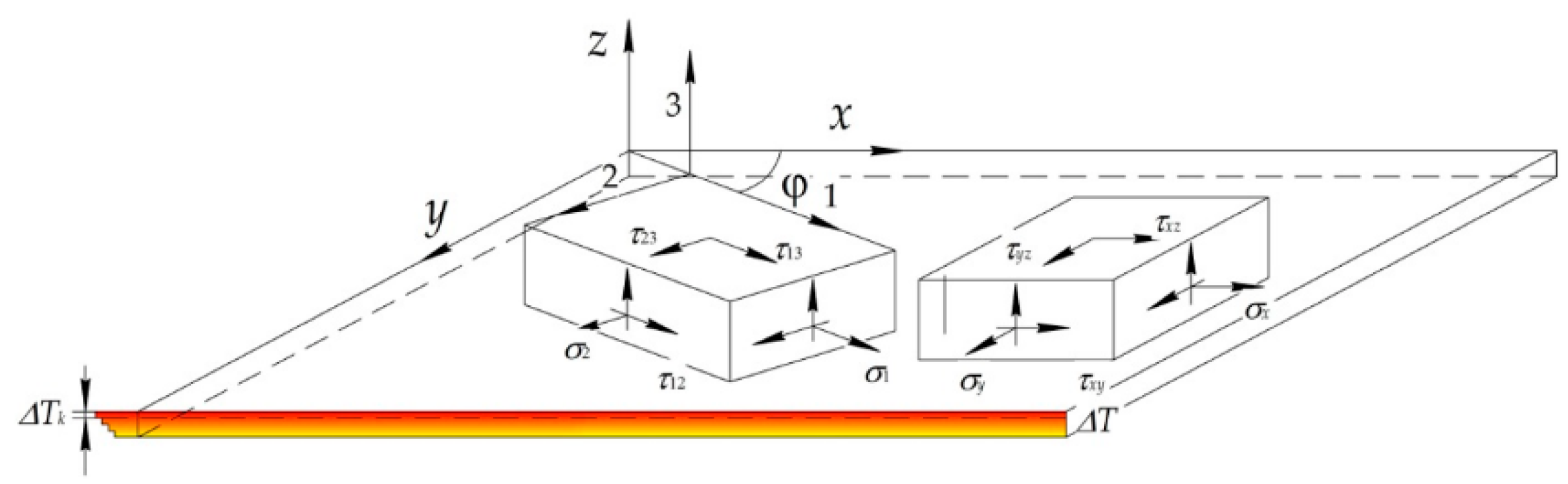
3. Theoretical Background
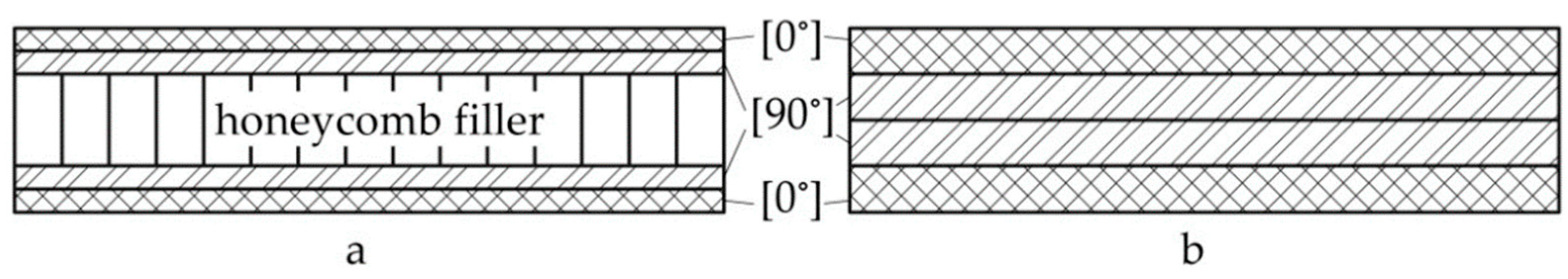
- sandwich panel with honeycomb filler of 4 mm high and four bearing layers of glass cloth (Figure 3a);
- sandwich panel with honeycomb filler of 9 mm high and four bearing layers of glass cloth (Figure 3a);
- glass cloth laminated panel with a monolayer of 0.25 mm thickness (Figure 3b).
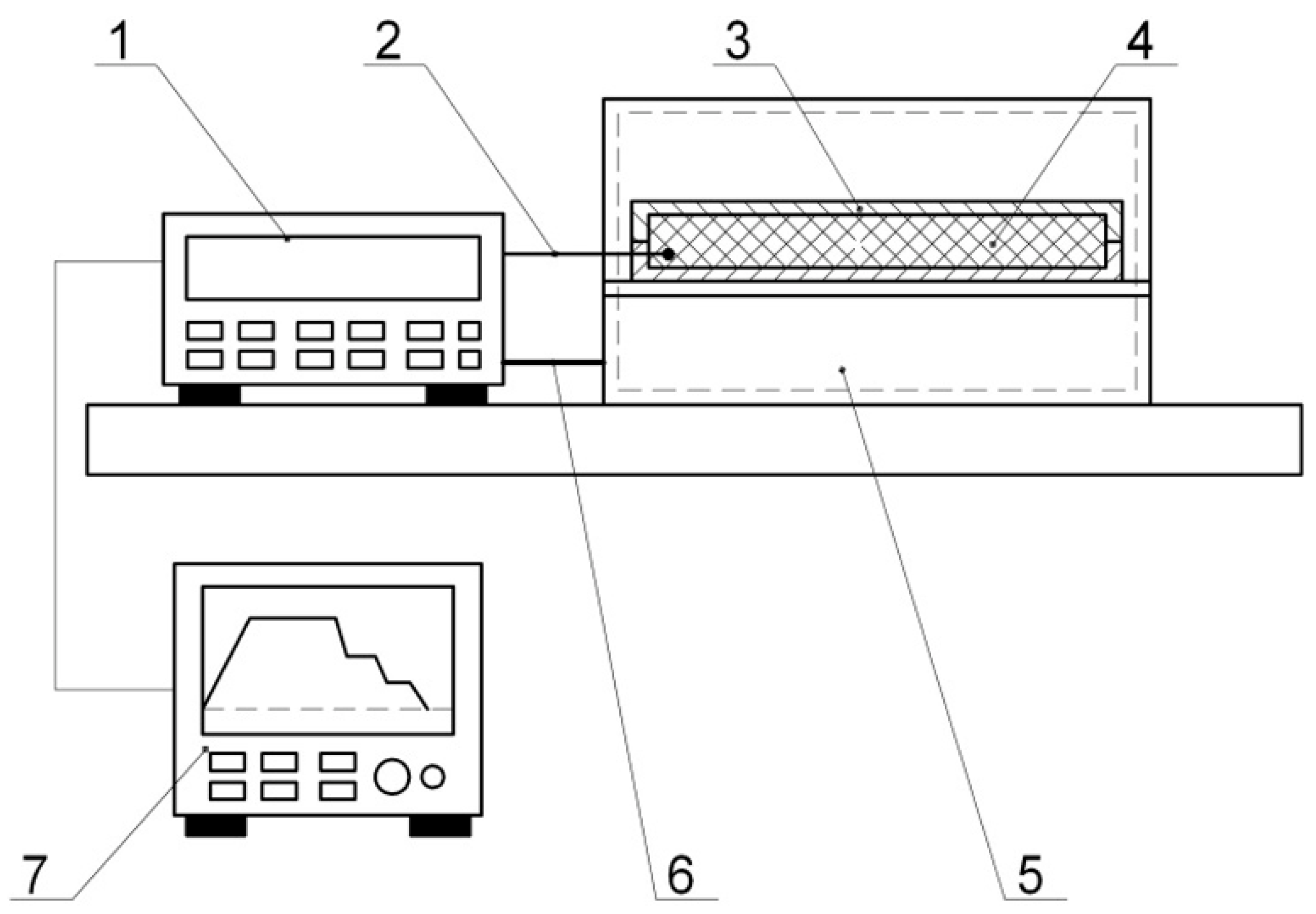
4. Experimental Research
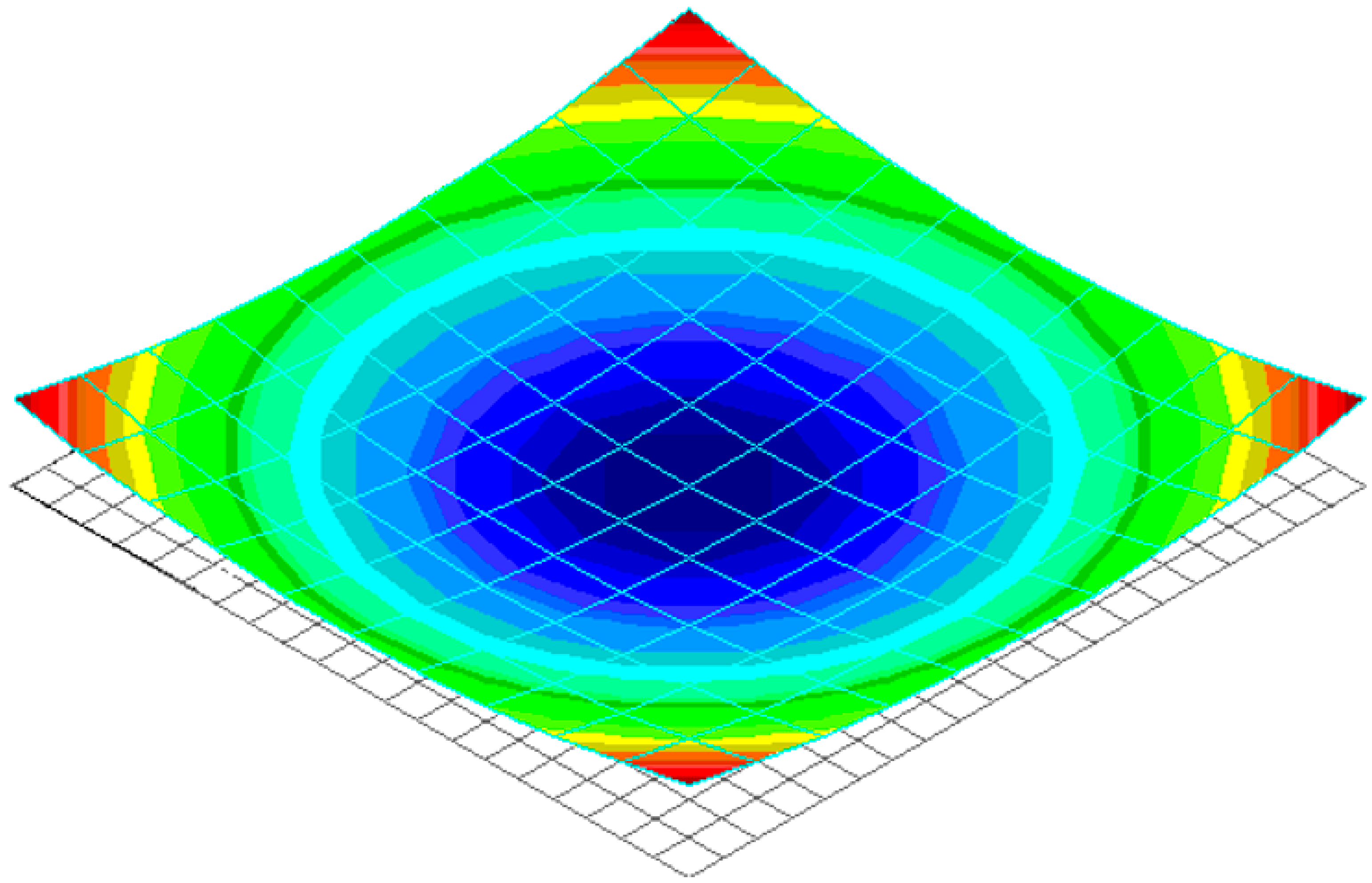
5. Results and Discussion
6. Conclusions and Further Research
Author Contributions
Funding
Institutional Review Board Statement
Informed Consent Statement
Data Availability Statement
Acknowledgments
Conflicts of Interest
References
- Rubino, F.; Nisticò, A.; Tucci, F.; Carlone, P. Marine Application of Fiber Reinforced Composites: A Review. J. Mar. Sci. Eng. 2020, 8, 26. [Google Scholar] [CrossRef] [Green Version]
- Slyvynskyi, V.I.; Sanin, A.F.; Kharchenko, M.E.; Kondratyev, A.V. Thermally and dimensionally stable structures of carbon-carbon laminated composites for space applications. In Proceedings of the 65th International Astronautical Congress 2014: Our World Needs Space, Toronto, ON, Canada, September 29–3 October 2014; Volume 8, pp. 5739–5751. [Google Scholar]
- Elfaki, I.; Abdalgadir, S. Composite sandwich structures in advanced civil engineering applications–A review. Comput. Res. Prog. Appl. Sci. Eng. 2020, 6, 259–262. [Google Scholar]
- Ugrimov, S.; Smetankina, N.; Kravchenko, O.; Yareshchenko, V. Analysis of Laminated Composites Subjected to Impact. In Integrated Computer Technologies in Mechanical Engineering-2020. November 2020; Springer: Cham, Switzerland, 2021; Volume 188, pp. 234–246. [Google Scholar] [CrossRef]
- Hsissou, R.; Seghiri, R.; Benzekri, Z.; Hilali, M.; Rafik, M.; Elharfi, A. Polymer composite materials: A comprehensive review. Compos. Struct. 2021, 262, 113640. [Google Scholar] [CrossRef]
- Fomin, O.; Lovskaya, A.; Plakhtiy, A.; Nerubatsky, V. The influence of implementation of circular pipes in load-bearing structures of bodies of freight cars on their physico-mechanical properties. Sci. Bull. Nat. Mining Univ. 2017, 6, 89–96. [Google Scholar]
- Kondratiev, A.; Slivinsky, M. Method for determining the thickness of a binder layer at its non-uniform mass transfer inside the channel of a honeycomb filler made from polymeric paper. East.-Eur. J. Enterp. Technol. 2018, 5, 42–48. [Google Scholar] [CrossRef] [Green Version]
- Kondratiev, A.; Prontsevych, O. Stabilization of physical-mechanical characteristics of Honeycomb Filler based on the adjustment of technological techniques for its fabrication. East.-Eur. J. Enterp. Technol. 2018, 1, 71–77. [Google Scholar] [CrossRef] [Green Version]
- Gavva, L.M.; Firsanov, V.V. Mathematical Models and Methods for Calculating the Stress-Strain State of Aircraft Panels from Composite Materials Taking into Account the Production Technology. Mechan. Solids 2020, 55, 403–412. [Google Scholar] [CrossRef]
- Baran, I.; Cinar, K.; Ersoy, N.; Akkerman, R.; Hattel, J.H. A Review on the Mechanical Modeling of Composite Manufacturing Processes. Arch. Comput. Methods Eng. 2017, 24, 365–395. [Google Scholar] [CrossRef] [Green Version]
- Kim, S.S.; Murayama, H.; Kageyama, K.; Uzawa, K.; Kanai, M. Study on the curing process for carbon/epoxy composites to reduce thermal residual stress. Compos. Part A Appl. Sci. Manuf. 2012, 43, 1197–1202. [Google Scholar] [CrossRef]
- Boitsov, B.V.; Gavva, L.M.; Pugachev, Y.N. The Stress–Strain State of Structurally Anisotropic Panels from Composite Materials under Force and Process Temperature Exposure. Polym. Sci. Ser. D 2019, 12, 85–90. [Google Scholar] [CrossRef]
- Tiwary, A.; Kumar, R.; Chohan, J.S. A review on characteristics of composite and advanced materials used for aerospace applications. Mater. Today Proc. 2021; in press. [Google Scholar] [CrossRef]
- Budelmann, D.; Schmidt, C.; Meiners, D. Prepreg tack: A review of mechanisms, measurement, and manufacturing implication. Polym. Compos. 2020, 41, 3440–3458. [Google Scholar] [CrossRef]
- Zhang, G.M.; Wang, J.H.; Ni, A.Q.; Li, S.X. Process-induced residual stress of variable-stiffness composite laminates during cure. Compos. Struct. 2018, 204, 12–21. [Google Scholar] [CrossRef]
- Kondratiev, A.; Gaidachuk, V.; Nabokina, T.; Kovalenko, V. Determination of the influence of deflections in the thickness of a composite material on its physical and mechanical properties with a local damage to its wholeness. East.-Eur. J. Enterp. Technol. 2019, 1, 6–13. [Google Scholar] [CrossRef]
- Carlone, P.; Rubino, F.; Paradiso, V.; Tucci, F. Multi-scale modeling and online monitoring of resin flow through dual-scale textiles in liquid composite molding processes. Int. J. Adv. Manuf. Technol. 2018, 96, 2215–2230. [Google Scholar] [CrossRef]
- Lionetto, F.; Moscatello, A.; Totaro, G.; Raffone, M.; Maffezzoli, A. Experimental and Numerical Study of Vacuum Resin Infusion of Stiffened Carbon Fiber Reinforced Panels. Materials 2020, 13, 4800. [Google Scholar] [CrossRef]
- Rocha, H.; Semprimoschnig, C.; Nunes, J.P. Sensors for process and structural health monitoring of aerospace composites: A review. Eng. Struct. 2021, 237, 112231. [Google Scholar] [CrossRef]
- Karpus, V.; Ivanov, V.; Dehtiarov, I.; Zajac, J.; Kurochkina, V. Technological assurance of complex parts manufacturing. Lect. Not. Mechan. Eng. 2019, 51–61. [Google Scholar] [CrossRef]
- Otrosh, Y.; Kovalov, A.; Semkiv, O.; Rudeshko, I.; Diven, V. Methodology remaining lifetime determination of the building structures. In Proceedings of the 7th International Scientific Conference “Reliability and Durability of Railway Transport Engineering Structures and Buildings”, Transbud-2011, Kharkiv, Ukraine, 14–16 November 2018; Volume 230, pp. 1–7. [Google Scholar] [CrossRef] [Green Version]
- Fomin, O.; Gerlici, J.; Lovskaya, A.; Kravchenko, K.; Prokopenko, P.; Fomina, A.; Hauser, V. Research of the strength of the bearing structure of the flat wagon body from round pipes during transportation on the railway ferry. In Proceedings of the 10th International Scientific Conference Horizons of Railway Transport, HORT 2018, Strecno, Slovakia, 11–12 October 2018; Volume 235, pp. 1–5. [Google Scholar] [CrossRef]
- Slyvynskyi, V.I.; Alyamovskyi, A.I.; Kondratjev, A.V.; Kharchenko, M.E. Carbon honeycomb plastic as light-weight and durable structural material. In Proceedings of the 63rd International Astronautical Congress 2012, Naples, Italy, 1–5 October 2012; Curran: Red Hook, NY, USA, 2012; Volume 8, pp. 6519–6529. [Google Scholar]
- Tkachenko, D.; Tsegelnyk, Y.; Myntiuk, S.; Myntiuk, V. Spectral Methods Application in Problems of the Thin-walled Structures Deformation. J. Appl. Comput. Mechan. 2022, 8, 641–654. [Google Scholar] [CrossRef]
- Suriani, M.J.; Rapi, H.Z.; Ilyas, R.A.; Petru, M.; Sapuan, S.M. Delamination and Manufacturing Defects in Natural Fiber-Reinforced Hybrid Composite: A Review. Polymers 2021, 13, 1323. [Google Scholar] [CrossRef]
- Fedulov, B.N. Modeling of manufacturing of thermoplastic composites and residual stress prediction. Aerosp. Syst. 2018, 1, 81–86. [Google Scholar] [CrossRef] [Green Version]
- Li, D.N.; Li, X.D.; Dai, J.F.; Xi, S.B. A Comparison of Curing Process-Induced Residual Stresses and Cure Shrinkage in Micro-Scale Composite Structures with Different Constitutive Laws. Appl. Compos. Mater. 2018, 25, 67–84. [Google Scholar] [CrossRef]
- Yuan, Z.Y.; Wang, Y.J.; Yang, G.G.; Tang, A.F.; Yang, Z.C.; Li, S.J.; Li, Y.; Song, D.L. Evolution of curing residual stresses in composite using multi-scale method. Compos. Part B-Eng. 2018, 155, 49–61. [Google Scholar] [CrossRef]
- Brauner, C.; Frerich, T.; Herrmann, A.S. Cure-dependent thermomechanical modelling of the stress relaxation behaviour of composite materials during manufacturing. J. Compos. Mater. 2017, 51, 877–898. [Google Scholar] [CrossRef]
- Cameron, C.J.; Saseendran, S.; Stig, F.; Rouhi, M. A rapid method for simulating residual stress to enable optimization against cure induced distortion. J. Compos. Mater. 2021, 55, 3799–3812. [Google Scholar] [CrossRef]
- Sfar Zbed, R.; Sobotka, V.; Le Corre, S. A Three-Dimensional Thermo-Chemical Characterization during the Whole Curing Cycle of a Carbon/Epoxy Prepreg. In Proceedings of the 24th International Conference on Material Forming (ESAFORM 2021), Online, 14–16 April 2021. [Google Scholar] [CrossRef]
- Nixon-Pearson, O.J.; Belnoue, J.P.H.; Ivanov, D.S.; Potter, K.D.; Hallett, S.R. An experimental investigation of the consolidation behaviour of uncured prepregs under processing conditions. J. Compos. Mater. 2017, 51, 1911–1924. [Google Scholar] [CrossRef]
- Kondratiev, A.; Píštěk, V.; Smovziuk, L.; Shevtsova, M.; Fomina, A.; Kučera, P.; Prokop, A. Effects of the Temperature–Time Regime of Curing of Composite Patch on Repair Process Efficiency. Polymers 2021, 13, 4342. [Google Scholar] [CrossRef] [PubMed]
- Kondratiev, A.; Píštěk, V.; Smovziuk, L.; Shevtsova, M.; Fomina, A.; Kučera, P. Stress–strain behaviour of reparable composite panel with step–variable thickness. Polymers 2021, 13, 3830. [Google Scholar] [CrossRef]
- Muliana, A.H. Spatial and temporal changes in physical properties of epoxy during curing and their effects on the residual stresses and properties of cured epoxy and composites. Appl. Eng. Sci. 2021, 7, 100061. [Google Scholar] [CrossRef]
- Fernlund, G.; Rahman, N.; Courdji, R.; Bresslauer, M.; Poursartip, A.; Willden, K.; Nelson, K. Experimental and numerical study of the effect of cure cycle, tool surface, geometry, and lay-up on the dimensional fidelity of autoclave-processed composite parts. Compos. Part A-Appl. Sci. Manuf. 2002, 33, 341–351. [Google Scholar] [CrossRef]
- Dveirin, O.Z.; Andreev, O.V.; Kondrat’ev, A.V.; Haidachuk, V.Y. Stressed State in the Vicinity of a Hole in Mechanical Joint of Composite Parts. Int. Appl. Mechan. 2021, 57, 234–247. [Google Scholar] [CrossRef]
- Grigorenko, A.Y.; Grigorenko, Y.M.; Müller, W.H.; Vlaikov, G.G. Recent Developments in Anisotropic Heterogeneous Shell Theory: General Theory and Applications of Classical Theory-Volume 1. SpringerBriefs Cont. Mechan. 2016. [Google Scholar] [CrossRef]
- Vasiliev, V.V.; Morozov, E.V. Chapter 3-Mechanics of Laminates. In Advanced Mechanics of Composite Materials and Structures, 4th ed.; Vasiliev, V.V., Morozov, E.V., Eds.; Elsevier: Amsterdam, The Netherlands, 2018; pp. 191–242. [Google Scholar] [CrossRef]
- Vasiliev, V.V.; Morozov, E.V. Chapter 5-Environmental, Special Loading, and Manufacturing Effects. In Advanced Mechanics of Composite Materials and Structures, 4th ed.; Vasiliev, V.V., Morozov, E.V., Eds.; Elsevier: Amsterdam, The Netherlands, 2018; pp. 295–375. [Google Scholar] [CrossRef]
- Kondratiev, A.; Píštěk, V.; Purhina, S.; Shevtsova, M.; Fomina, A.; Kučera, P. Self-Heating Mould for Composite Manufacturing. Polymers 2021, 13, 3074. [Google Scholar] [CrossRef] [PubMed]
- Centea, T.; Grunenfelder, L.K.; Nutt, S.R. A review of out-of-autoclave prepregs-Material properties, process phenomena, and manufacturing considerations. Compos. Part A-Appl. Sci. Manuf. 2015, 70, 132–154. [Google Scholar] [CrossRef]
- Shevtsova, M.; Smovziuk, L. Prompt Repair of Damaged Aircraft Skin Panels; National Aerospace University “Kharkiv Aviation Institute” Publ.: Kharkiv, Ukraine, 2016. [Google Scholar]
- Birman, V.; Kardomateas, G.A. Review of current trends in research and applications of sandwich structures. Compos. Part B-Eng. 2018, 142, 221–240. [Google Scholar] [CrossRef]


| Heating Rate, °C/min | PCM Package Thickness, mm | ||
|---|---|---|---|
| Sandwich Panel | Laminated Panel | ||
| 5 | 10 | 1 | |
| 3 | 0.04 | 0.019 | 3.2 |
| 2 | 0.03 | 0.013 | 2.1 |
| 1 | 0.01 | ~0.00 | 0.98 |
| Heating Rate, °C/min | Layers | |||||||
|---|---|---|---|---|---|---|---|---|
| Panel of 5 mm Thick | Panel of 10 mm Thick | |||||||
| No 1 | No 2 | No 3 | No 4 | No 1 | No 2 | No 3 | No 4 | |
| 3 | 2.9 | 1 | 0.03 | −0.1 | 13.9 | 4.3 | −0.05 | −0.52 |
| 2 | 1.9 | 0.6 | 0.02 | −0.07 | 8.8 | 2.9 | −0.04 | −0.35 |
| 1 | 0.95 | 0.31 | 0.01 | −0.04 | 4.7 | 1.5 | −0.02 | −0.1 |
| Heating Rate, °C/min | Layers | |||
|---|---|---|---|---|
| No 1 | No 2 | No 3 | No 4 | |
| 3 | 0.32 | 0.08 | 0.05 | −0.015 |
| 2 | 0.21 | 0.06 | 0.03 | −0.01 |
| 1 | 0.11 | 0.03 | 0.02 | −0.005 |
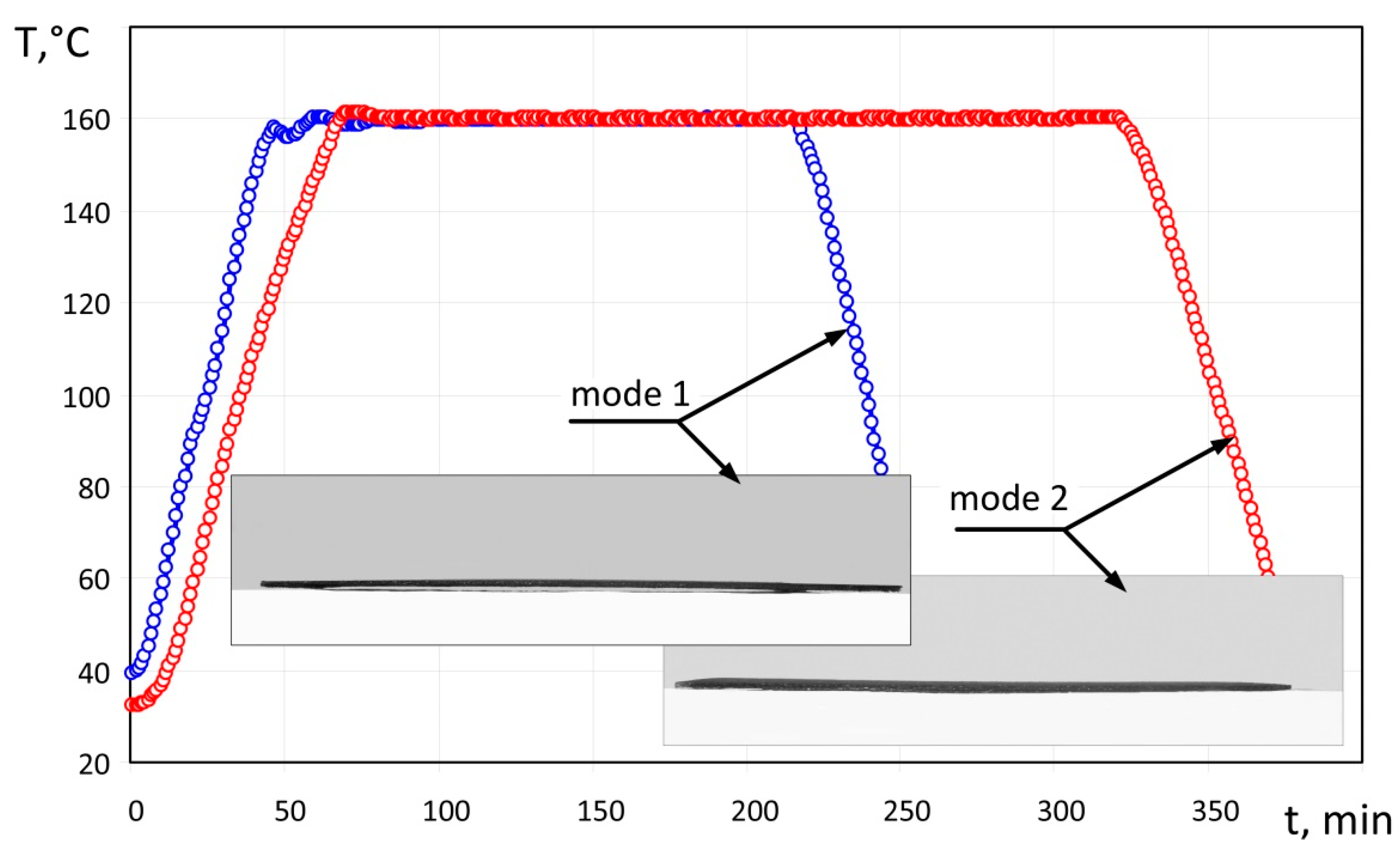
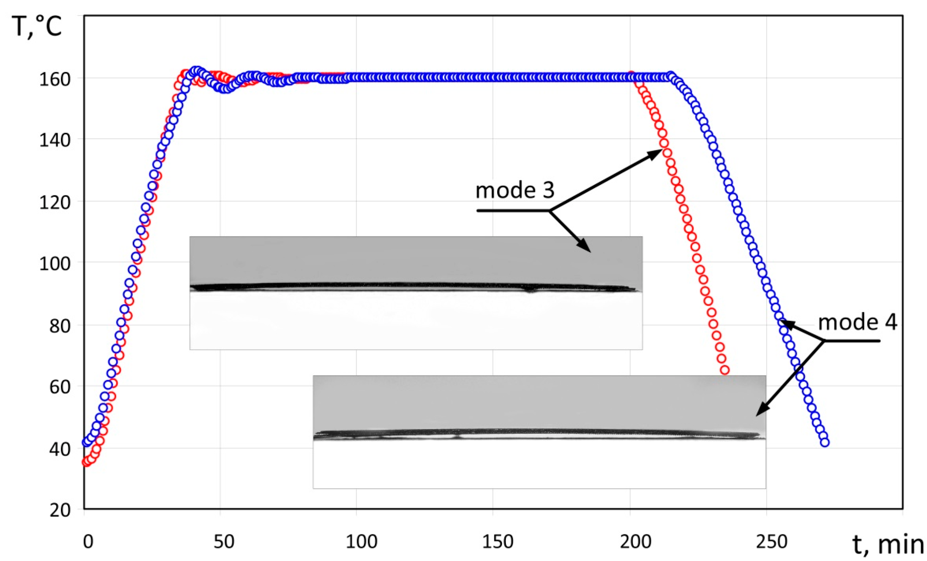
| Moulding Mode | Heating Rate, °C/min | Cooling Rate, °C/min | Deflection, mm | Notes |
|---|---|---|---|---|
| No 1 (Figure 6) | 2.8 | 3.5 | 1.9 | Surface is smooth, without any visible defects. |
| No 2 (Figure 6) | 2.0 | 2.3 | 0.7 | Surface is smooth, without any visible defects. |
| No 3 (Figure 7 and Figure 8) | 3.6 | 3.5 | 2.3 | Surface is wavy with swellings. Delamination of edges and partial delamination of the upper layer is observed. |
| No 4 (Figure 7) | 3.8 | 2.5 | 2.5 | Surface is smooth, without any visible defects. Slight delamination is observed on edges of the specimen. |
| Heating Rate, °C/min | Temperature, T, °C | ||||
|---|---|---|---|---|---|
| 20 | 50 | 100 | 150 | 200 | |
| 1 | 0.21 | 0.23 | 0.23 | 0.19 | 0.13 |
| 2 | 0.83 | 0.89 | 0.89 | 0.75 | 0.5 |
| 3 | 2.14 | 2.30 | 2.30 | 1.95 | 1.30 |
| 4 | 3.11 | 3.35 | 3.34 | 2.83 | 1.89 |
| Moulding Mode | , mm | ||||
|---|---|---|---|---|---|
| 1 | 1.9 | 2.00 | 1.82 | 5.3 | 4.2 |
| 2 | 0.7 | 0.83 | 0.75 | 18.6 | 7.1 |
| 3 | 2.3 | 2.70 | 2.45 | 17.4 | 6.5 |
| 4 | 2.5 | 2.93 | 2.67 | 17.2 | 6.8 |
Publisher’s Note: MDPI stays neutral with regard to jurisdictional claims in published maps and institutional affiliations. |
© 2022 by the authors. Licensee MDPI, Basel, Switzerland. This article is an open access article distributed under the terms and conditions of the Creative Commons Attribution (CC BY) license (https://creativecommons.org/licenses/by/4.0/).
Share and Cite
Kondratiev, A.; Píštěk, V.; Vambol, O.; Kučera, P. Effect of Heating Conditions during Moulding on Residual Stress–Strain Behaviour of a Composite Panel. Polymers 2022, 14, 1660. https://doi.org/10.3390/polym14091660
Kondratiev A, Píštěk V, Vambol O, Kučera P. Effect of Heating Conditions during Moulding on Residual Stress–Strain Behaviour of a Composite Panel. Polymers. 2022; 14(9):1660. https://doi.org/10.3390/polym14091660
Chicago/Turabian StyleKondratiev, Andrii, Václav Píštěk, Oleksii Vambol, and Pavel Kučera. 2022. "Effect of Heating Conditions during Moulding on Residual Stress–Strain Behaviour of a Composite Panel" Polymers 14, no. 9: 1660. https://doi.org/10.3390/polym14091660