
Design and Evaluation of a Polymer Support Fluid in a Soil–Rock Mixture


Abstract
:1. Introduction
2. Materials and Methods
2.1. Materials
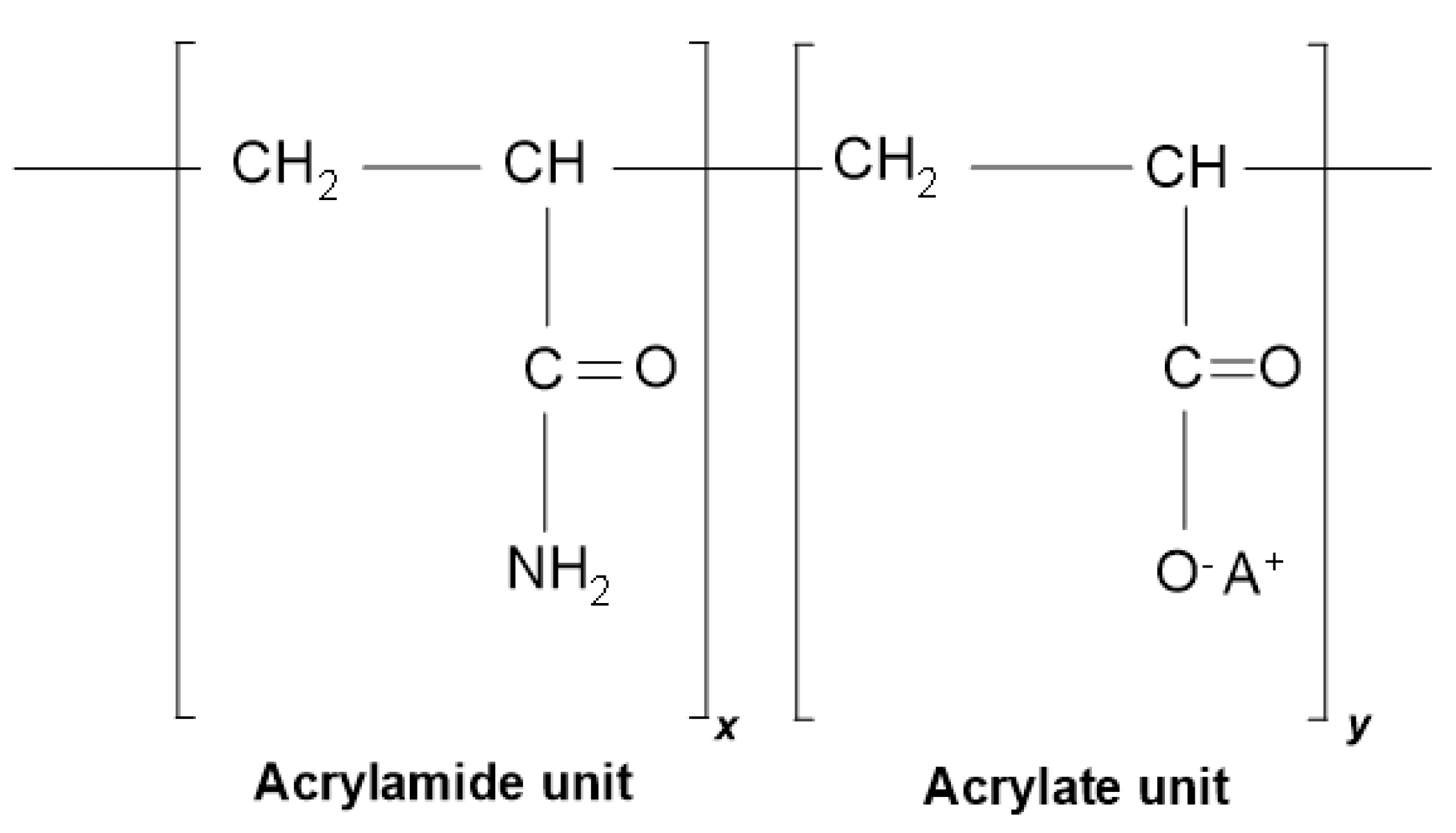
2.1.1. Polymer
2.1.2. Bentonite
2.1.3. Soil–Limestone Mixture
2.1.4. Silty Clay
2.1.5. Solvent
2.2. Methods
2.2.1. Preparation of Polymer Fluid
2.2.2. Preparation of Bentonite Fluid
2.2.3. Preparation of Polymer Mixed Silty Clay
2.2.4. Observation of Polymer Microstructure
2.2.5. Fluid Performance Test
3. Results
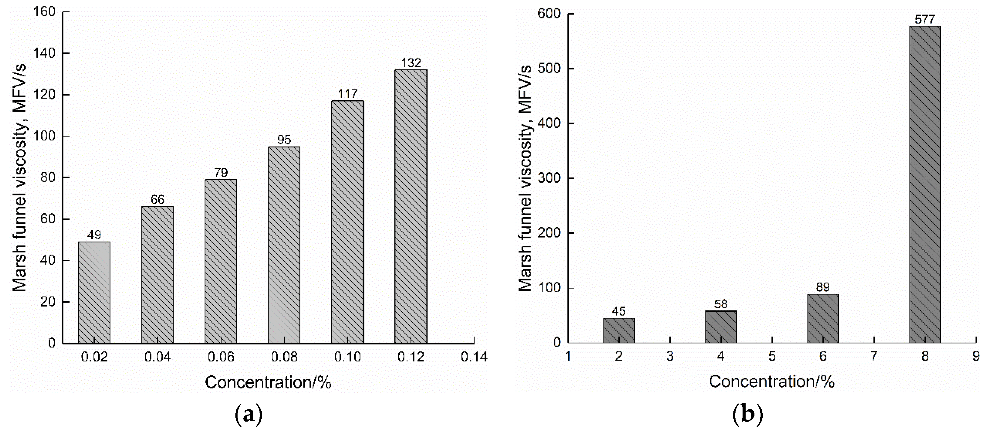
3.1. Screening Tests on Polymer Concentration
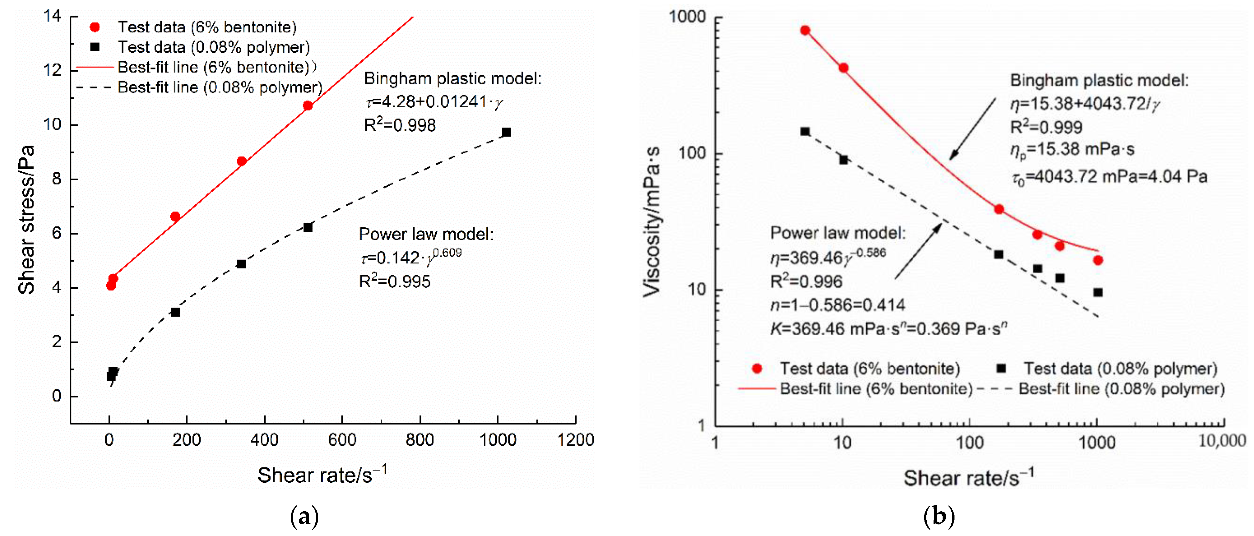
3.2. Fluids Flow Patterns
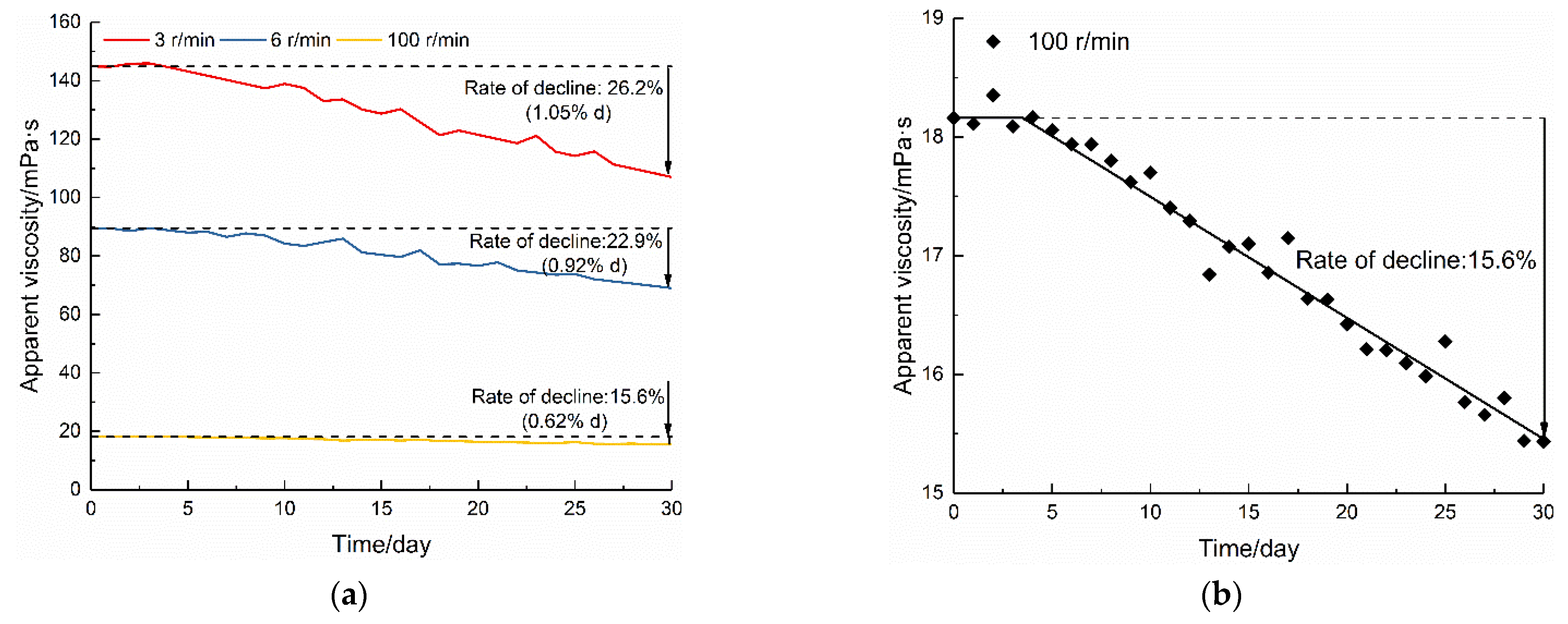
3.3. Aging Behavior of Polymer Fluids
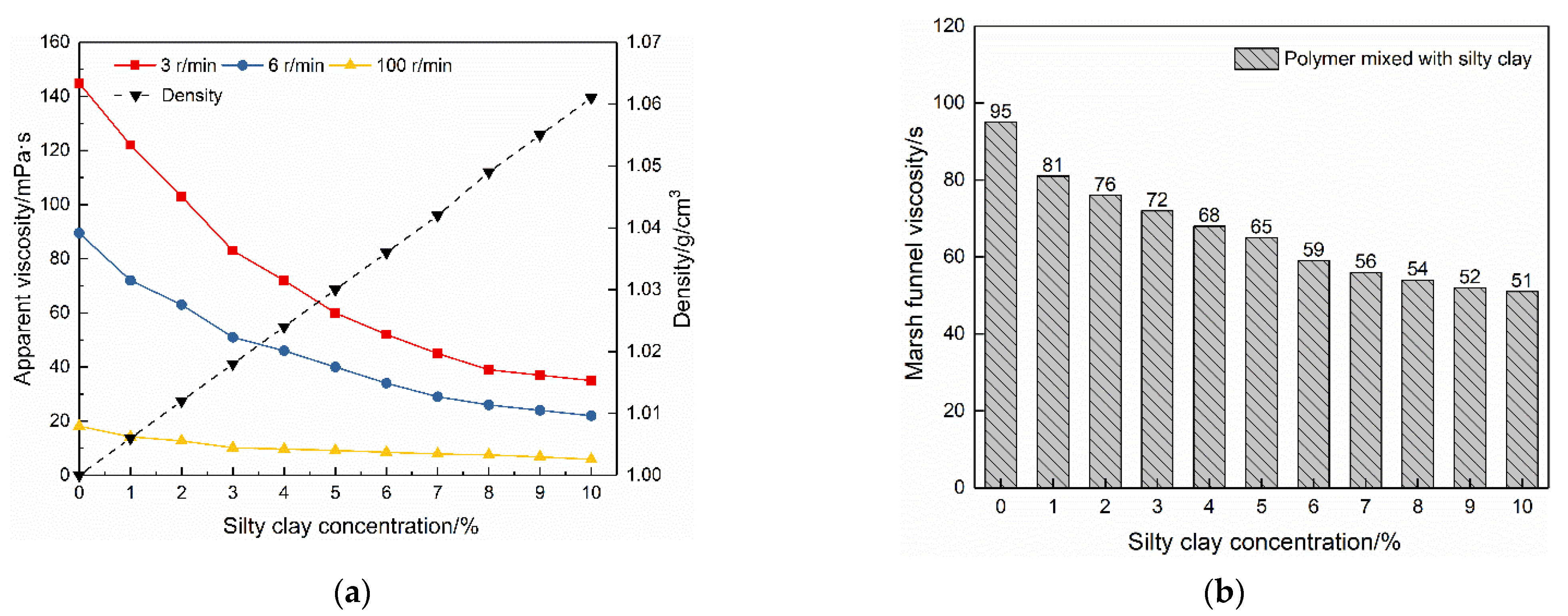
3.4. Effect of Polymer Fluids Mixing with Silty Clay
3.5. Polymer Fluid Formula
4. Discussion
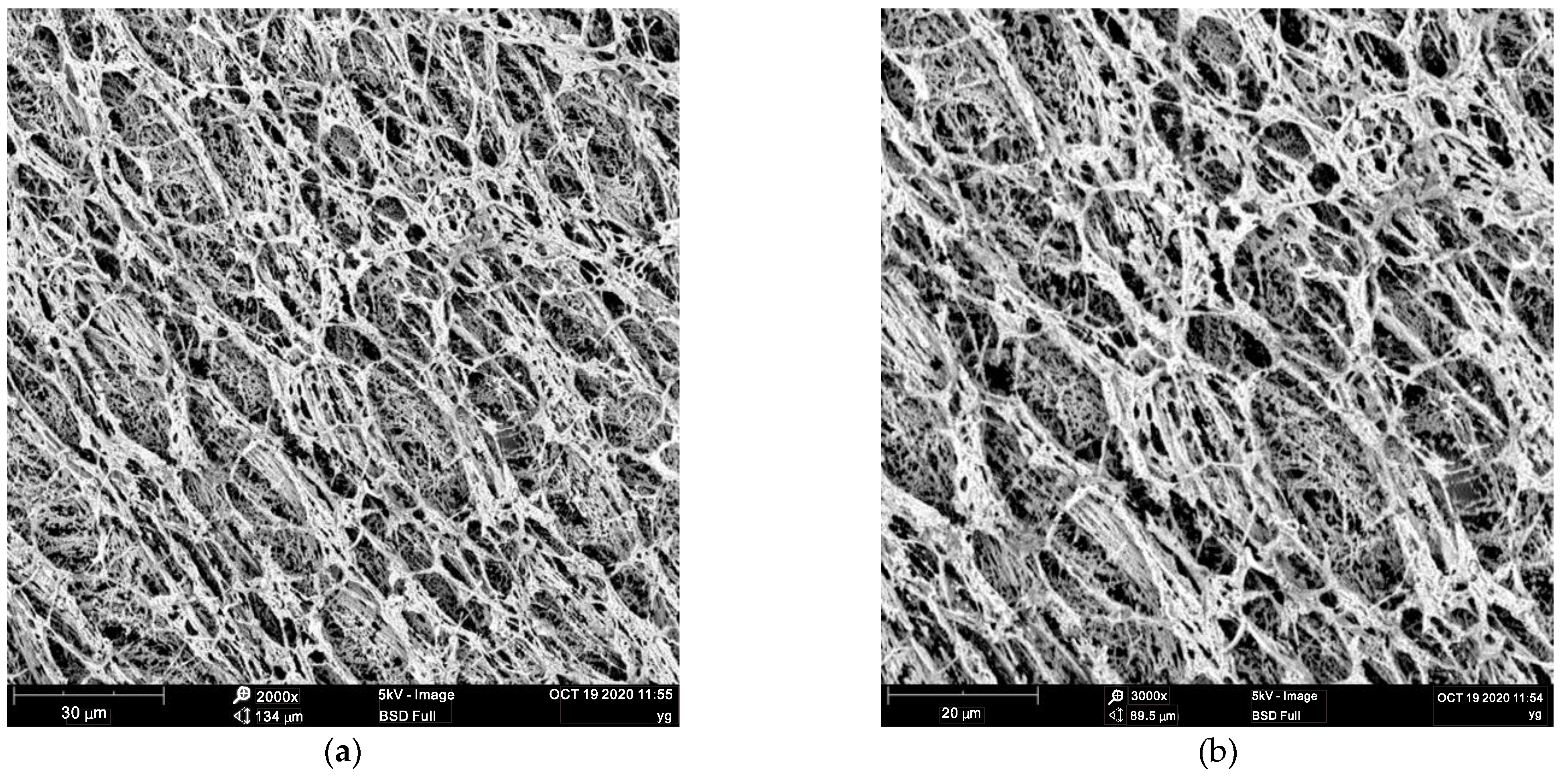
4.1. Microstructure of the Polymer Fluid
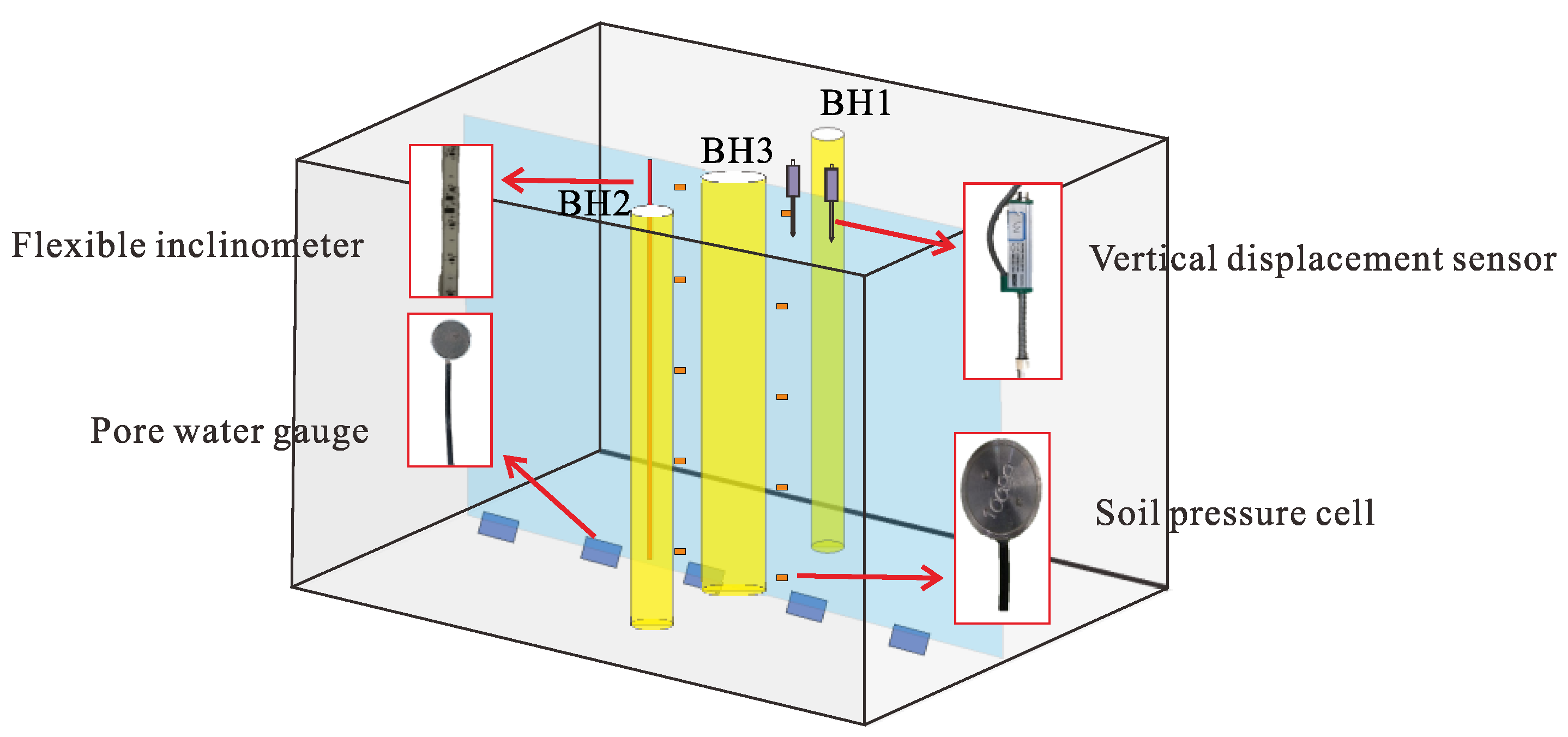
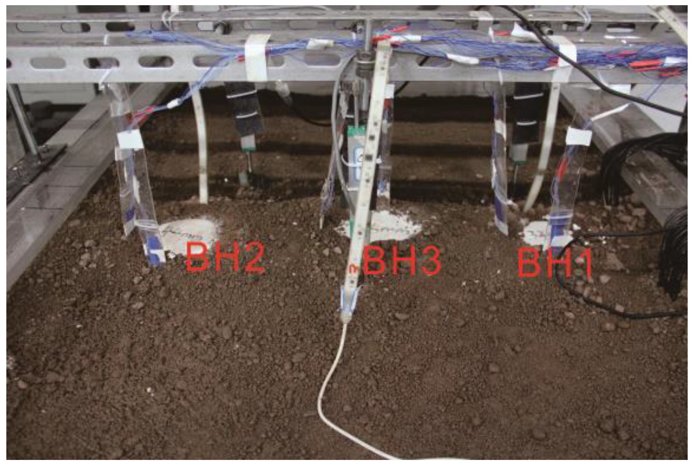
4.2. Validation of the Polymer Fluid Formula
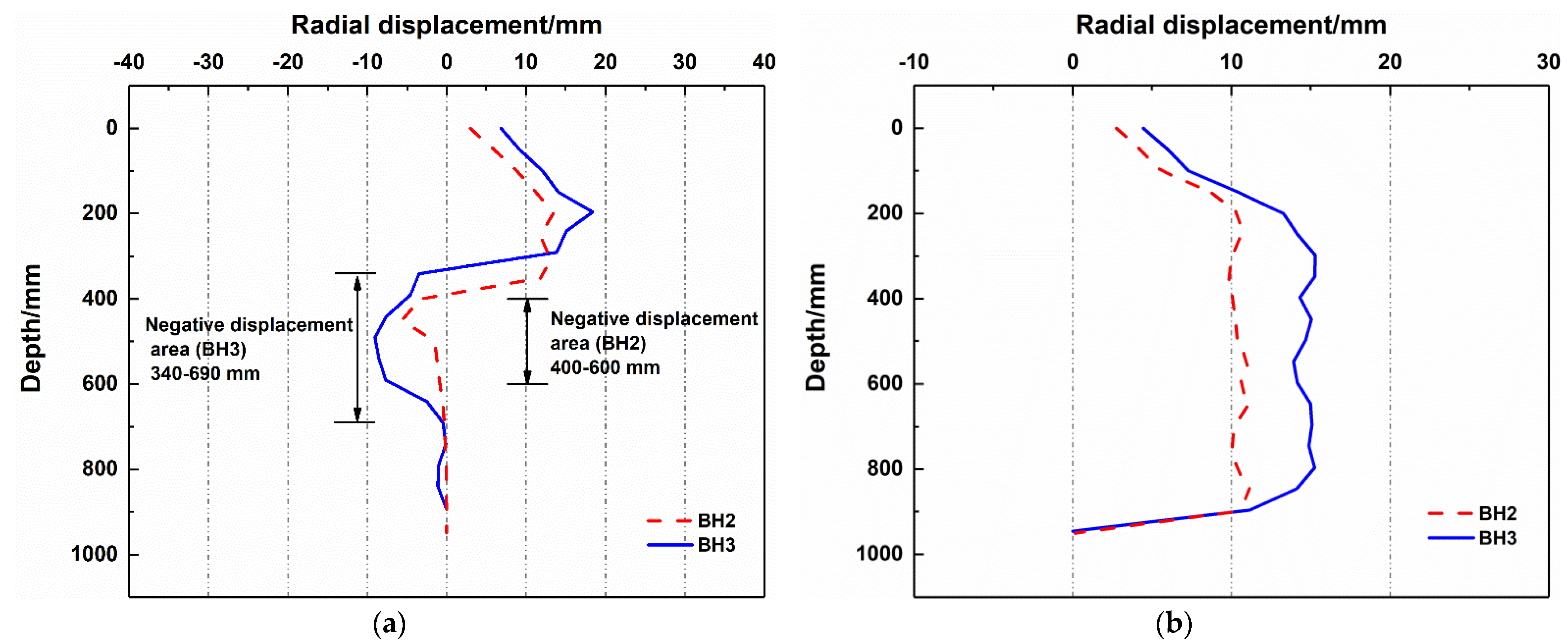
4.2.1. Horizontal Radial Displacements
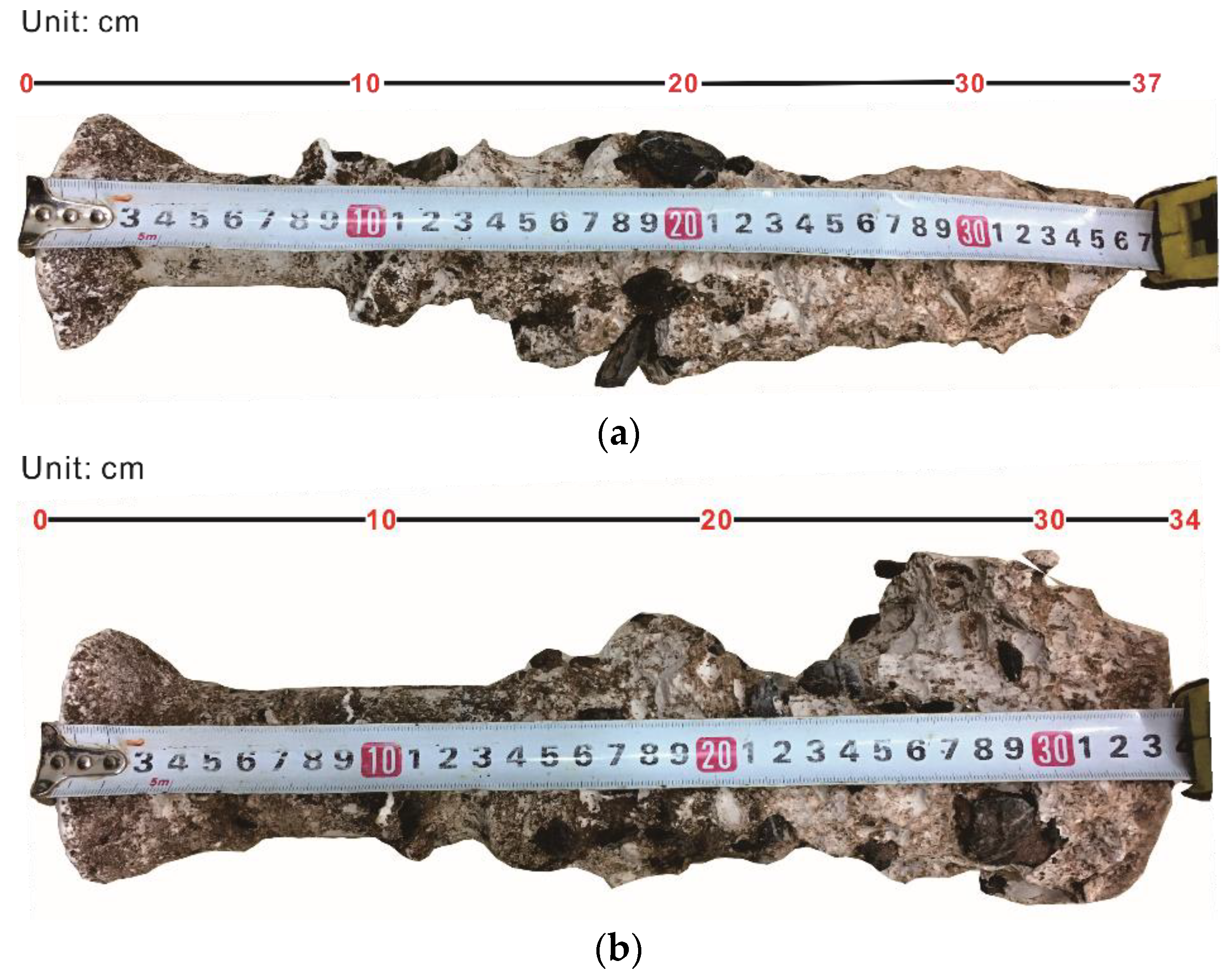
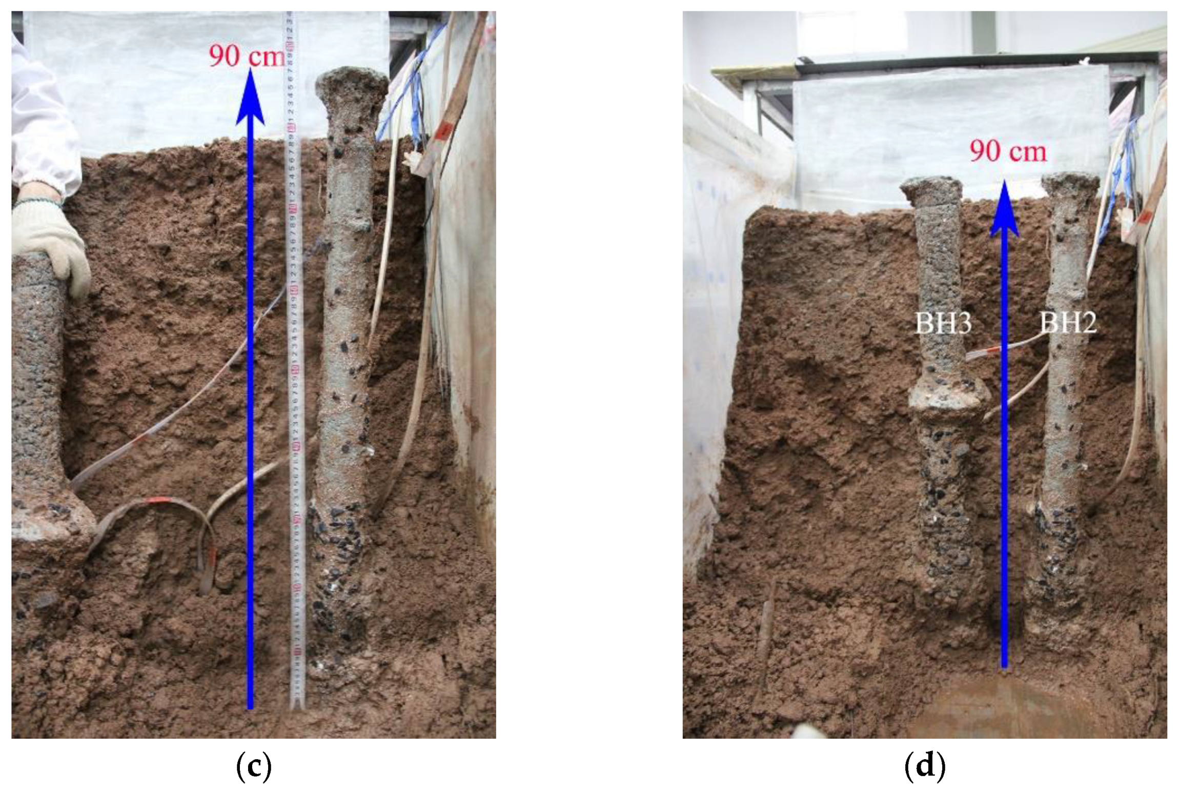
4.2.2. Comparison of Pile Morphology after Drilling
5. Conclusions
- An amount of 0.08% polymer fluid was a good alternative for the conventional 6% bentonite fluid, with 95 s and 89 s in Marsh funnel viscosity, respectively. Within the shear rate 5~1022 s−1, polymer fluids were reasonably well fitted to the power–law model, while bentonite fluids were suitable for the Bingham plastic model.
- After a prolonged aging time of up to 30 days, the remaining active viscosity was at least 70%, which would promote confidence in utilizing polymer fluids as they will inevitably be placed for several days or even months at an actual job site.
- Adding silty clay to the polymer fluids significantly reduced the apparent viscosity. As the dosage of silty clay increased from 3% to 10%, the rate of apparent viscosity reduction was from 50% to almost 76%, indicating the effective fluid management was to control silty clay on site during soil and rock mixture excavation.
- A polymer drilling fluid formula: water + 0.08%PHPA + 0.1~0.5%Na2CO3 was proposed. Verified by drilling into a soi–limestone mixture, the formula has excellent lubrication performance and supportability, which causes small radial displacements around the boreholes and high drilling quality.
Author Contributions
Funding
Institutional Review Board Statement
Informed Consent Statement
Data Availability Statement
Conflicts of Interest
References
- Kristiansen, T.G.; Mandziuch, K.; Heavey, P.; Kol, H. Minimizing drilling risk in extended-reach wells at Valhall using geomechanics, geoscience and 3D visualization technology. In Proceedings of the SPE/IADC Drilling Conference, Amsterdam, The Netherlands, 9–11 March 1999. SPE 52863. [Google Scholar]
- Bruce, D.A.; Lyon, R. Recent Advances in Overburden and Down-the-Hole Drilling Techniques. In Proceedings of the Grouting 2017, Honolulu, HI, USA, 9–12 July 2017; pp. 82–91. [Google Scholar]
- Veder, C. Method for the construction of impermeable diaphragms at great depth by means of thixotropic muds. In Proceedings of the 3rd International Conference of Soil Mechanics and Foundations Engineering, Zurich, Switzerland, 16–27 August 1953; pp. 91–94. [Google Scholar]
- Shrivastava, A.K.; Jain, D.; Vishwakarma, S. Frictional resistance of drilling fluids as a borehole stabilizers. Int. J. Geo-Eng. 2016, 7, 12. [Google Scholar] [CrossRef] [Green Version]
- Lam, C.; Jefferis, S.; Troughton, V. Polymer systems for fluid supported excavations. In Proceedings of the Geotechnical Issues in Construction: Short Paper Series and 2nd Conference, CIRIA, London, UK, 22 November 2011; pp. 7–12. [Google Scholar]
- Lam, C.; Jefferis, S.A. Physical properties of polymer support fluids in use and their measurement techniques. Geotech. Test. J. 2015, 38, 490–500. [Google Scholar] [CrossRef]
- Corbet, S.P.; Culley, D.S.; Sherwood, D.E.; Cockcroft, J.E.M. Testing and analysis of preliminary test piles in very weak chalk. In Proceedings of the Fourth International Conference on Piling and Deep Foundations, Balkema, Rotterdam, The Netherlands, 7–12 April 1991; pp. 57–63. [Google Scholar]
- Wheeler, P. Piles Unlock Polymer Potential; European Found: Dublin, Ireland, 2003; pp. 8–9. [Google Scholar]
- Lam, C.; Troughton, V.M.; Jefferis, S.A.; Suckling, T.P. Effect of support fluids on pile performance—A field trial in East London. Ground Eng. 2010, 43, 28–31. [Google Scholar]
- Lam, C. Properties and Applications of Polymer Support Fluids in Geotechnical Engineering. Ph.D. Thesis, University of Oxford, Oxford, UK, 2011. [Google Scholar]
- Bustamante, M.; Gianeselli, L.; Boato, R.; Conedera, A. Performance of polymer slurries in large diameter bored pile. In Proceedings of the Third International Seminar on Deep Foundations on Bored and Auger Piles, Balkema, Rotterdam, The Netherlands, 19–21 October 1998; pp. 119–127. [Google Scholar]
- Lam, C.; Jefferis, S.A.; Suckling, T.P. Construction techniques for bored piling in sand using polymer fluids. Proc. Inst. Civ. Eng.-Geotech. Eng. 2014, 167, 565–573. [Google Scholar] [CrossRef] [Green Version]
- Ejezie, J.O.; Jefferis, S.A.; Lam, C.; Sedighi, M.; Syed, A.S.M. Permeation behaviour of PHPA polymer fluids in sand. Géotechnique 2021, 71, 561–570. [Google Scholar] [CrossRef]
- Lesemann, H. Anwendung polymerer Stützflüssigkeiten bei der Herstellung von Bohrpfählen und Schlitzwänden. Ph.D. Thesis, Technical University of Munich, Munich, Germany, 2010. (In German). [Google Scholar]
- Lam, C.; Jefferis, S.A. Performance of bored piles constructed using polymer fluids: Lessons from European experience. J. Perform. Constr. Facil. 2016, 30, 04015024. [Google Scholar] [CrossRef] [Green Version]
- Lam, C.; Martin, P.J.; Jefferis, S.A. Rheological properties of PHPA polymer support fluids. J. Mater. Civ. Eng. 2015, 27, 04015021. [Google Scholar] [CrossRef] [Green Version]
- Lam, C.; Jefferis, S.A. Interpretation of viscometer test results for polymer support fluids. In Proceedings of the Sessions of Geo-Shanghai 2014, Shanghai, China, 26–28 May 2014; pp. 439–449. [Google Scholar]
- Kulicke, W.M.; Kniewske, R. Long-term change in conformation of macromolecules in solution, 2. Poly (acrylamide-co-sodium acrylate)s. Die Makromol. Chem. 1981, 182, 2277–2287. [Google Scholar] [CrossRef]
- Likos, W.J.; Loehr, J.E.; Akunuri, K. Engineering Evaluation of Polymer-Based Drilling Fluids for Applications in Missouri Shale; Department of Civil and Environmental Engineering, University of Missouri: Columbia, SC, USA, 2004; Report RDT-04-019. [Google Scholar]
- Henderson, J.M.; Wheatley, A.D. Factors effecting a loss of flocculation activity of polyacrylamide solutions: Shear degradation, cation complexation, and solution aging. J. Appl. Polym. Sci. 1987, 33, 669–684. [Google Scholar] [CrossRef]
- Lam, C.; Jefferis, S.A. Effect of sorption on the active concentration of polymer support fluids. Géotech. Lett. 2021, 11, 36–41. [Google Scholar] [CrossRef]
- Ying, C.; Hu, X.L.; Siddiqua, S.; Makeen, G.M.H.; Xia, P.; Xu, C.; Wang, Q. Model tests for observing the deformation characteristics of micropile boreholes during drilling in a soil-limestone mixture. Bull. Eng. Geol. Environ. 2021, 1–21. [Google Scholar] [CrossRef]
- Zhu, H.; Luo, J.; Sui, X.; Yao, T.; Yang, F.; Dai, S.; Yang, J. Microstructure of novel polymer solution used for oil displacement. Acta Petrolei Sin. 2006, 340, 79–83. (In Chinese) [Google Scholar]
- Coussot, P. Structural similarity and transition from Newtonian to non-Newtonian behavior for clay-water suspensions. Phys. Rev. Lett. 1995, 74, 3971. [Google Scholar] [CrossRef] [PubMed]
- Luckham, P.F.; Rossi, S. The colloidal and rheological properties of bentonite suspensions. Adv. Colloid Interface Sci. 1999, 82, 43–92. [Google Scholar] [CrossRef] [Green Version]
- Bekkour, K.; Leyama, M.; Benchabane, A.; Scrivener, O. Time-dependent rheological behavior of bentonite suspensions: An experimental study. J. Rheol. 2005, 49, 1329–1345. [Google Scholar] [CrossRef]
- Lam, C.; Jefferis, S.A. Ageing behaviour of polyacrylamide-based excavation fluids. Proc. Inst. Civ. Eng.-Constr. Mater. 2016, 169, 301–307. [Google Scholar] [CrossRef] [Green Version]
- Narkis, N.; Rebhun, M. Ageing effects in measurements of polyacrylamide solution viscosities. Polymer 1966, 7, 507–512. [Google Scholar] [CrossRef]
- Shyluk, W.P.; Stow, F.S., Jr. Aging and loss of flocculation activity of aqueous polyacrylamide solutions. J. Appl. Polym. Sci. 1969, 13, 1023–1036. [Google Scholar] [CrossRef]
- Zhang, X.W.; Guan, Y.J.; Zhou, J.H. Application of PHP slurry to drilling of overlength and extra-large -diameter bored piles. Chin. J. Rock Mech. Eng. 2005, 24, 2571–2575. (In Chinese) [Google Scholar]
- Lam Carlos Jefferis Stephan, A. Polymer Support Fluids in Civil Engineering; ICE Publishing: London, UK, 2018. [Google Scholar]
- Jeng, Y.R.; Chen, C.C.; Shyu, S.H. A molecular dynamics study of lubrication rheology of polymer fluids. Tribol. Lett. 2003, 15, 293–299. [Google Scholar] [CrossRef]
- Jefferis, S.A.; Lam, C. Polymer support fluids: Use and misuse of innovative fluids in geotechnical works. In Proceedings of the 18th International Conference on Soil Mechanics and Geotechnical Engineering, Paris, France, 2–6 September 2013; pp. 3219–3222. [Google Scholar]
- Liao, W.A.; Siems, D.R. Adsorption characteristics of PHPA on formation solids. In Proceedings of the IADC/SPE Drilling Conference, Houston, TX, USA, 27 February–2 March 1990. SPE-19945-MS. [Google Scholar]


| Dry Density (g/cm3) | Specific Gravity | Porosity (%) | w (%) | Grain Size Distribution (%) | |||||
|---|---|---|---|---|---|---|---|---|---|
| 20~40 | 10~20 | 5~10 | 2~5 | 0.005~2 | <0.005 | ||||
| 2.48 | 2.71 | 1.25 | 6 | 15 | 15 | 15 | 8 | 40 | 7 |
| Dry Density (g/cm3) | Specific Gravity | w (%) | wp (%) | wL (%) | Grain Size Distribution (%) | ||
|---|---|---|---|---|---|---|---|
| <0.005 | 0.005~0.075 | >0.075 | |||||
| 1.67 | 2.72 | 14.2 | 15.1 | 29.1 | 15.0 | 38.2 | 46.8 |
Publisher’s Note: MDPI stays neutral with regard to jurisdictional claims in published maps and institutional affiliations. |
© 2022 by the authors. Licensee MDPI, Basel, Switzerland. This article is an open access article distributed under the terms and conditions of the Creative Commons Attribution (CC BY) license (https://creativecommons.org/licenses/by/4.0/).
Share and Cite
Ying, C.; Hu, X.; Xia, P.; Zhang, H. Design and Evaluation of a Polymer Support Fluid in a Soil–Rock Mixture. Polymers 2022, 14, 1402. https://doi.org/10.3390/polym14071402
Ying C, Hu X, Xia P, Zhang H. Design and Evaluation of a Polymer Support Fluid in a Soil–Rock Mixture. Polymers. 2022; 14(7):1402. https://doi.org/10.3390/polym14071402
Chicago/Turabian StyleYing, Chunye, Xinli Hu, Peng Xia, and Haiyan Zhang. 2022. "Design and Evaluation of a Polymer Support Fluid in a Soil–Rock Mixture" Polymers 14, no. 7: 1402. https://doi.org/10.3390/polym14071402