
Exquisite Energy Savings at Cold Metal Forming of Threads through the Application of Polymers


Abstract
:1. Introduction
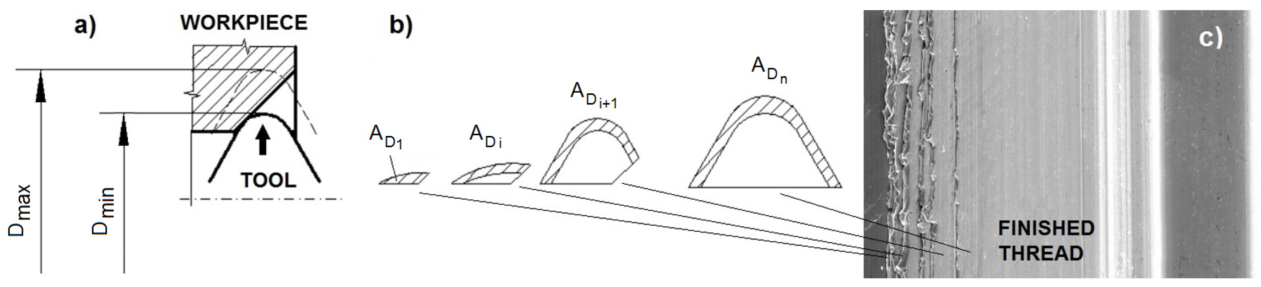
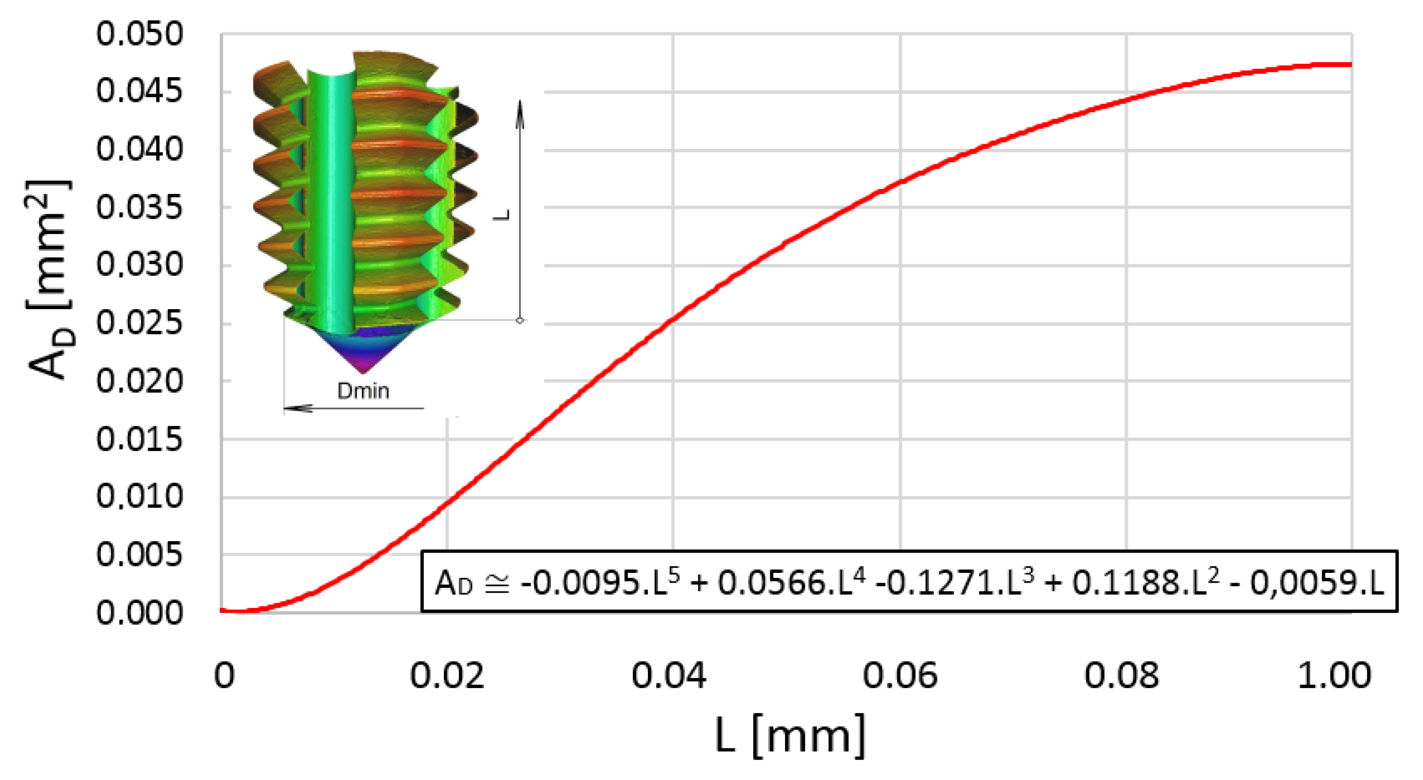
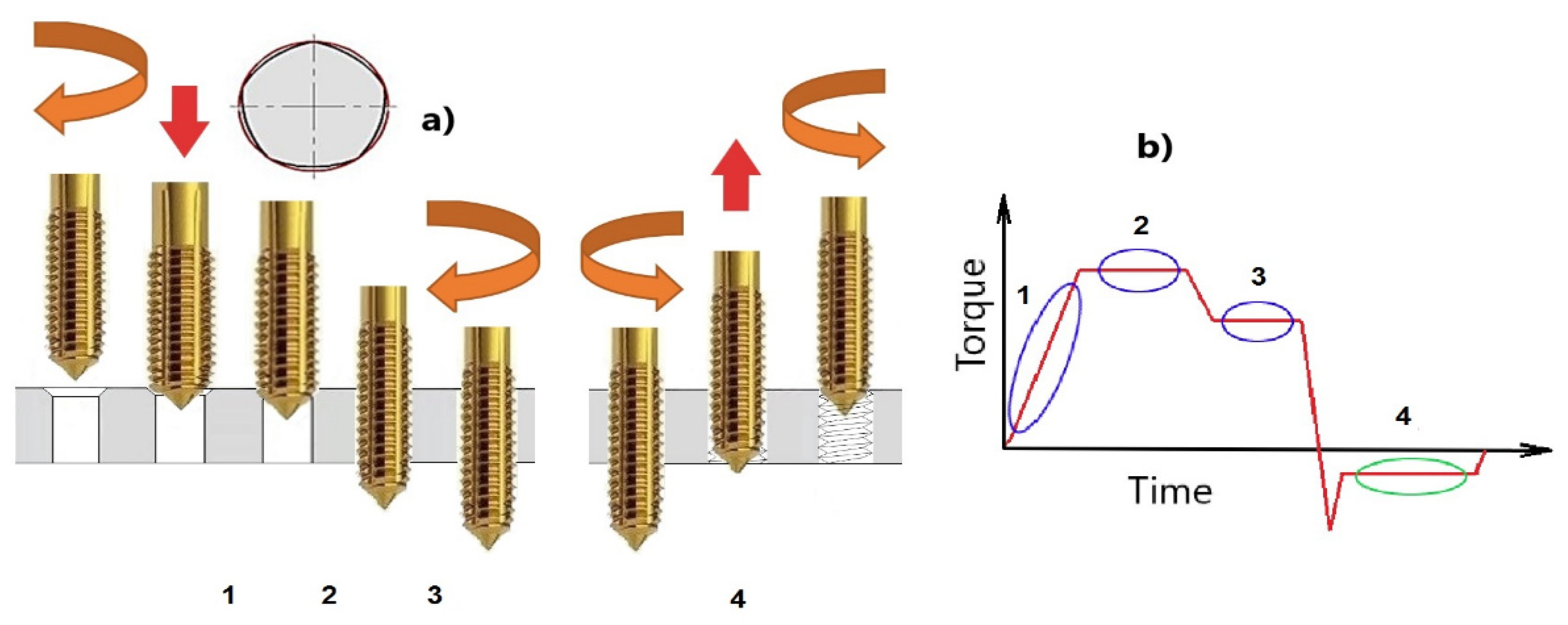
2. Theory
3. Materials
3.1. Polymer Characterization
- 1.
- The polymer soap “A”
- 2.
- Polymer Paste “B”
- 3.
- Polymer Paste “C”
- 4.
- Polymer Fluid “D”
- 5.
- Polymer Fluid “E”
- 6.
- Polymer Fluid “F”
- 7.
- Polymer fluid “G”
- 8.
- Polymer fluid “G+”
- 9.
- Polymer fluid “H” with nanoparticles WS2
- 10.
- Polymer fluid “I” with nanoparticles WS2 and MoS2
- 11.
- Polymer fluid “G++”
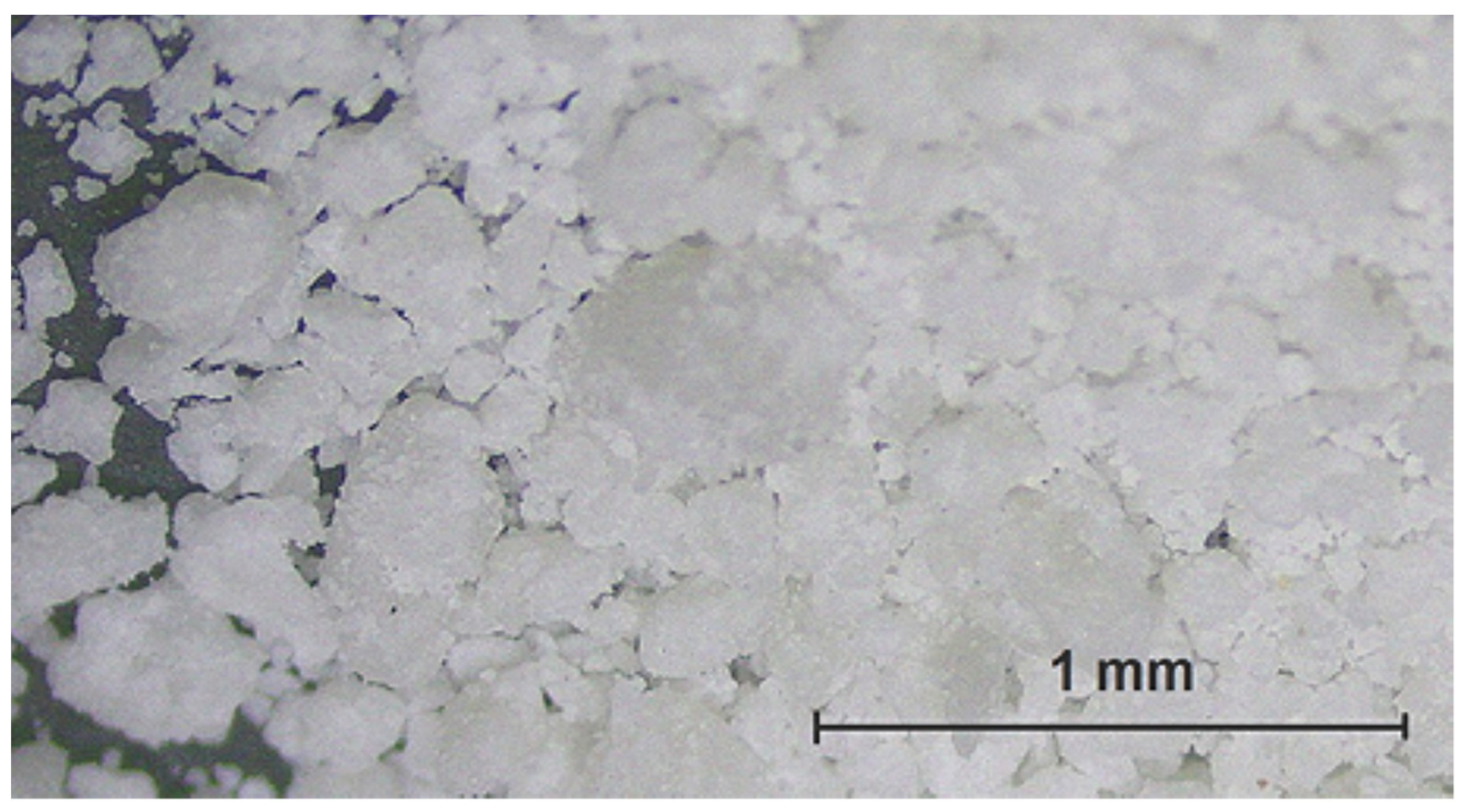
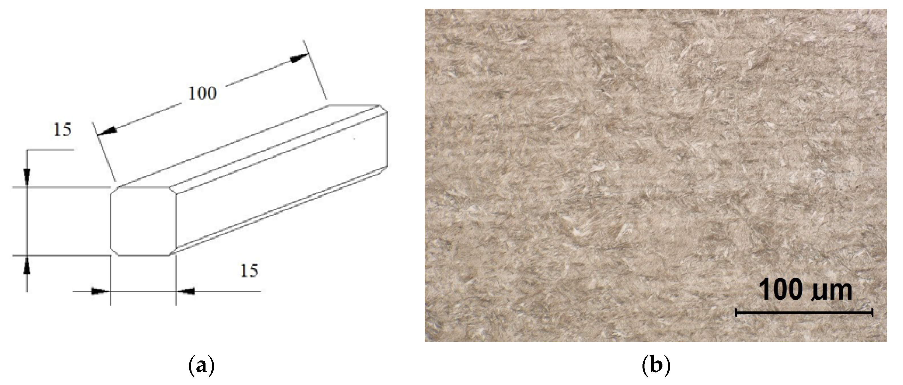
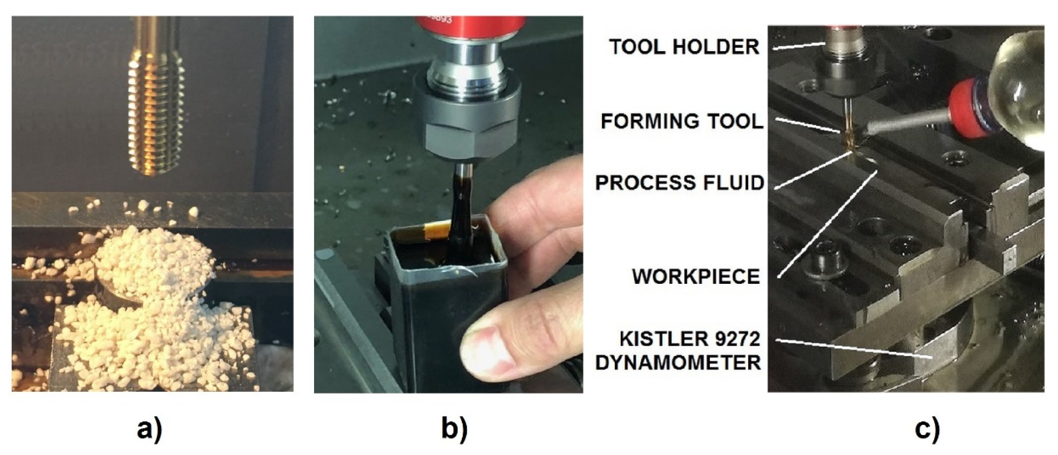
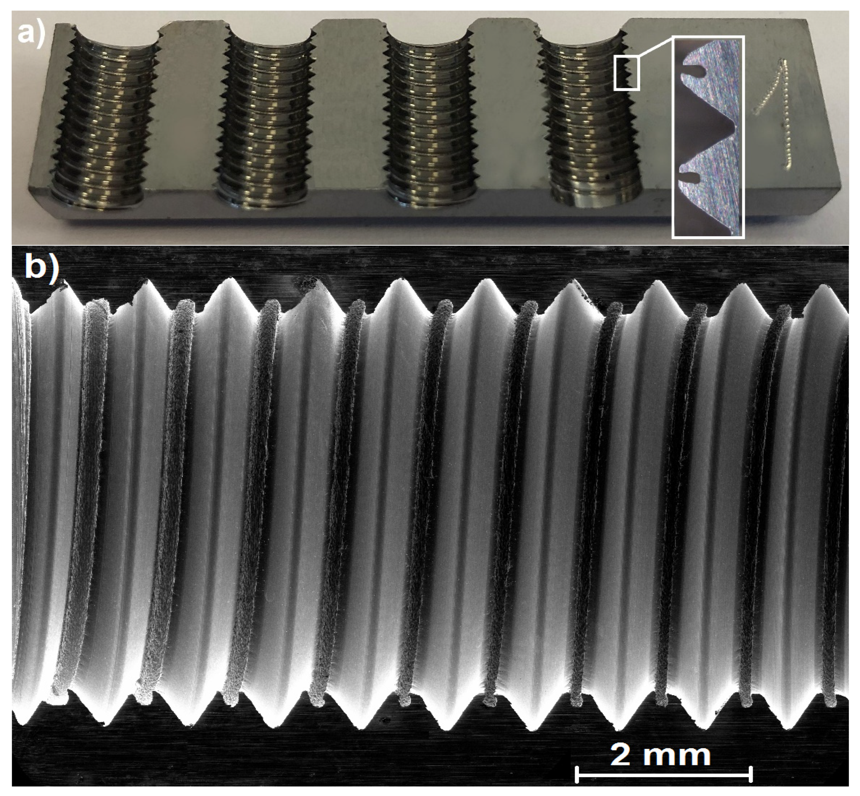
3.2. Tested Material and Tooling
3.3. Experimental Method
4. Results and Discussion
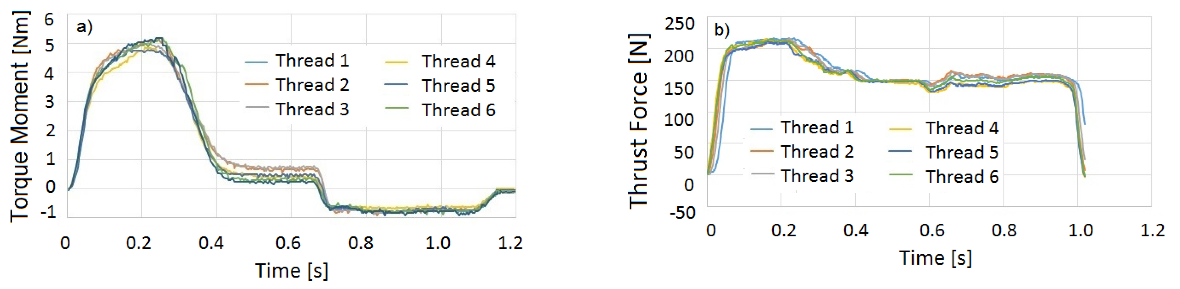
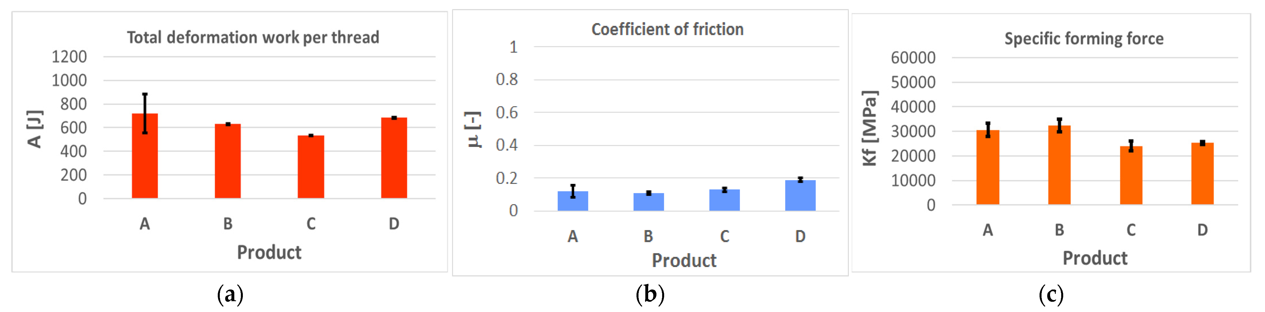
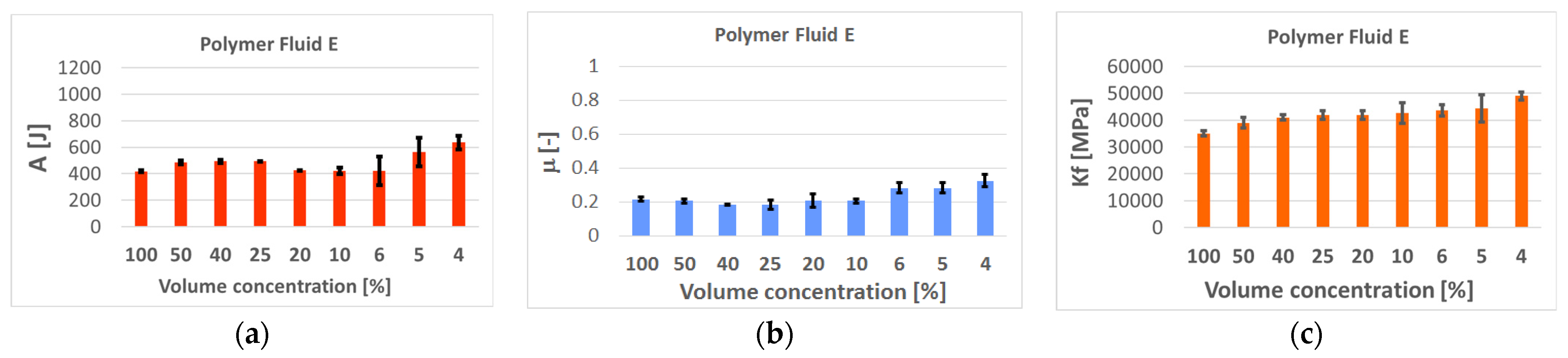
4.1. Evaluation of the Deformation Work, Coefficient of Friction, and the Specific Forming Force
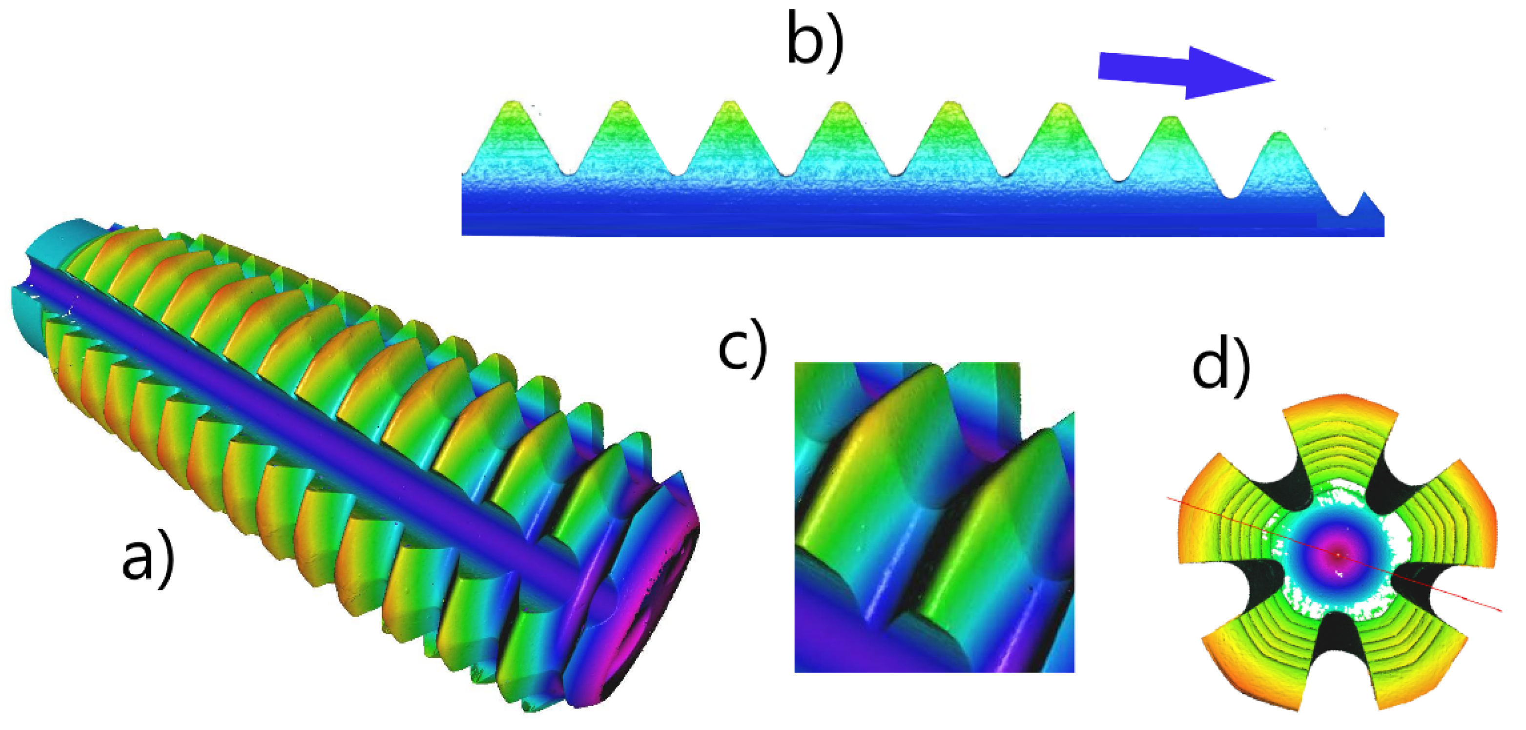
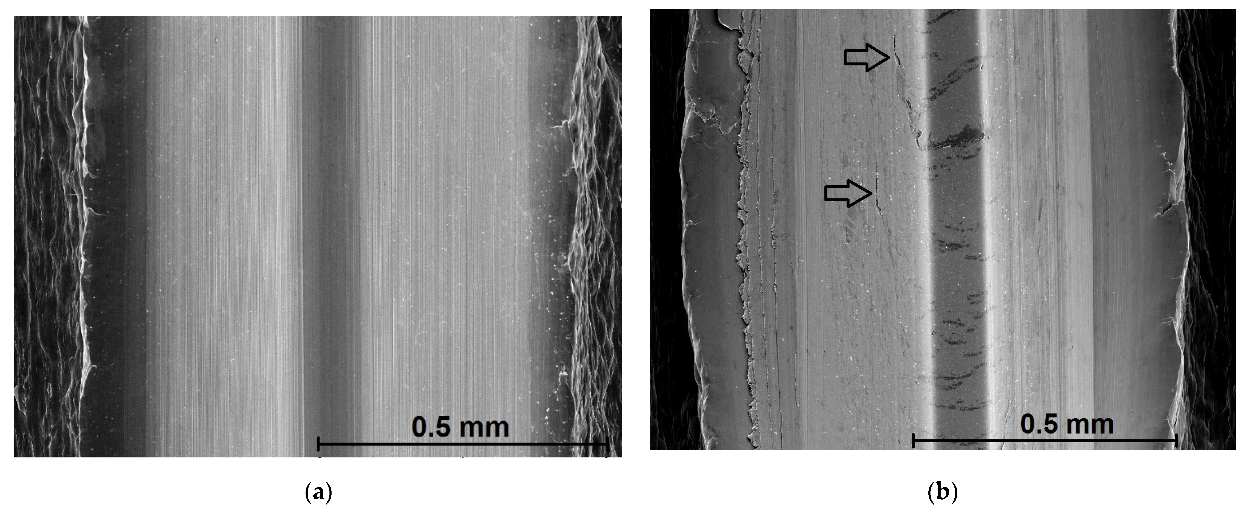
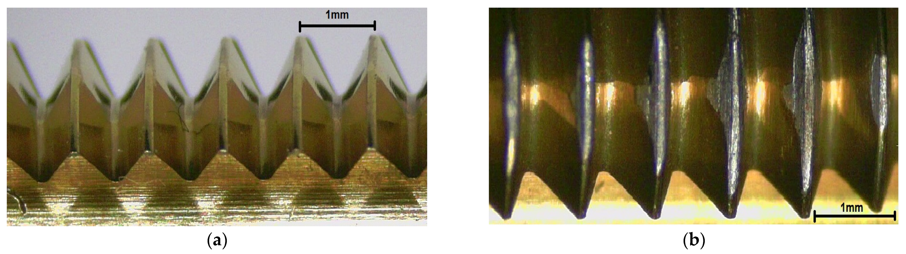
4.2. Evaluation of the Formed Thread Surface Quality
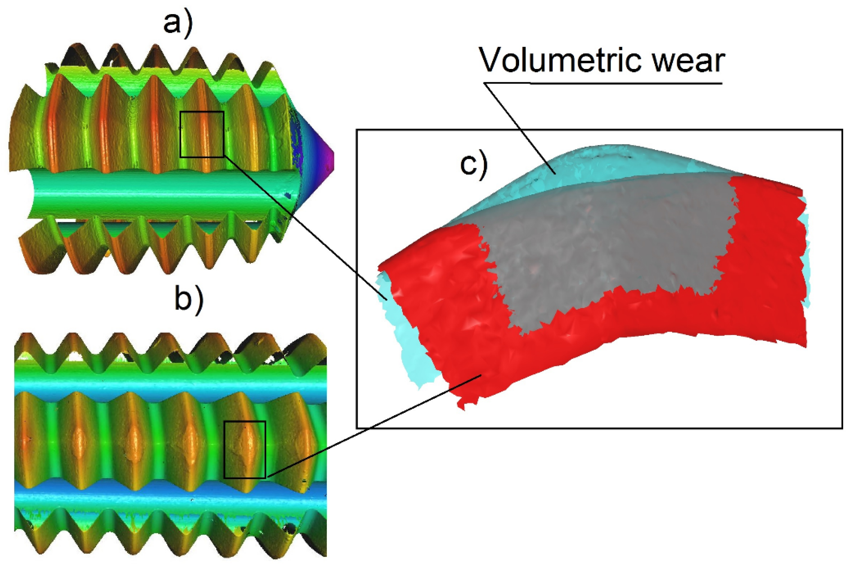
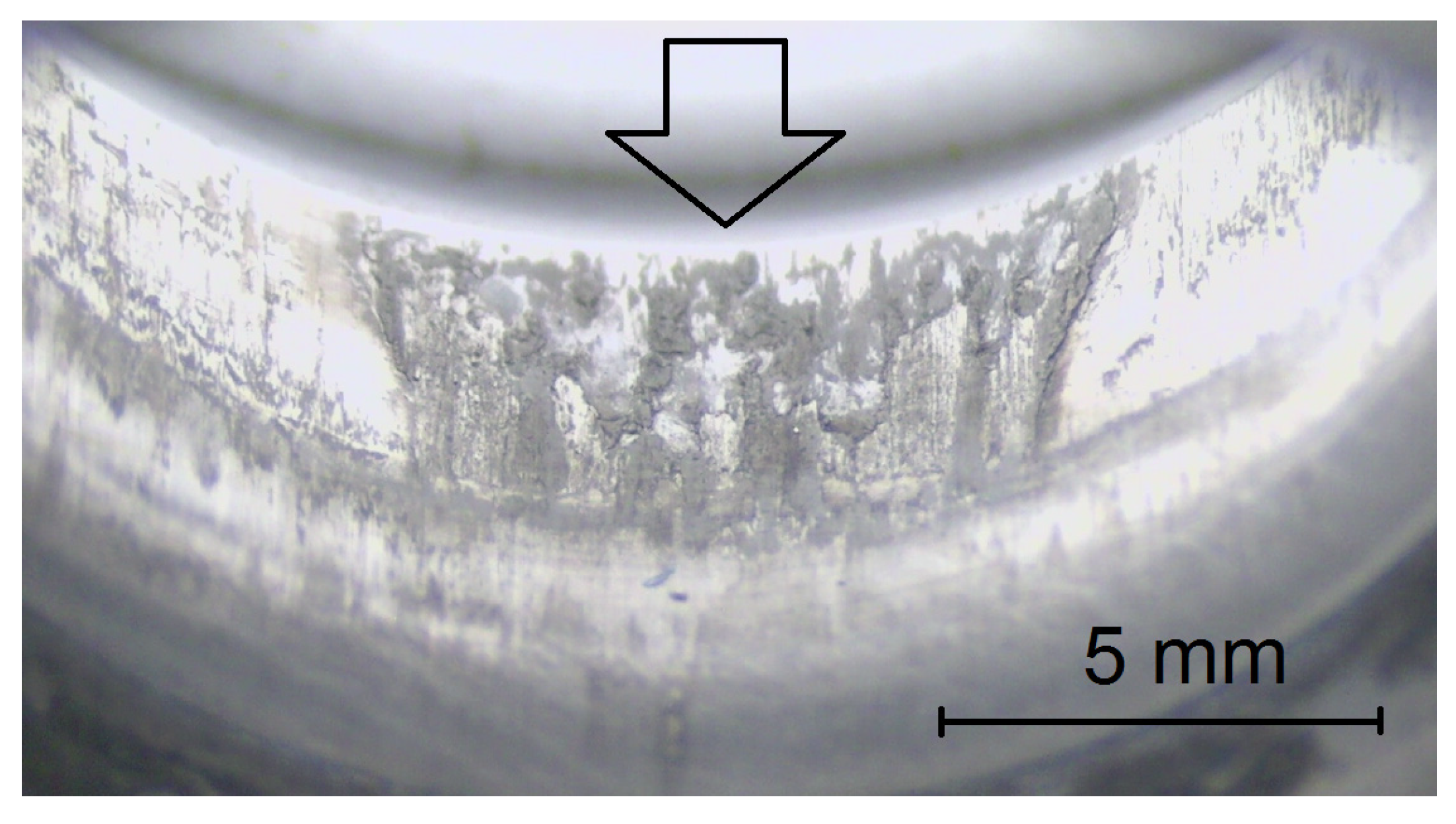
4.3. Wear of the Forming Taps
5. Conclusions
Supplementary Materials
Author Contributions
Funding
Institutional Review Board Statement
Informed Consent Statement
Acknowledgments
Conflicts of Interest
References
- Fromentin, G.; Poulachon, G.; Moisan, A.; Julien, B.; Giessler, J. Precision and surface integrity of threads obtained by form tapping. CIRP Ann. Manuf. Technol. 2005, 54, 519–522. [Google Scholar] [CrossRef]
- Fromentin, G.; Bierla, A.; Minfray, C.; Poulachon, G. An experimental study on the effects of lubrication in form tapping. Tribol. Int. 2010, 43, 1726–1734. [Google Scholar] [CrossRef] [Green Version]
- Winter, M.; Bock, R.; Herrmann, C. Investigation of a new polymer-water based cutting fluid to substitute mineral oil based fluids in grinding processes. CIRP J. Manuf. Sci. Technol. 2013, 6, 254–262. [Google Scholar] [CrossRef]
- Carou, D.; Rubio, E.; Benedicto, B. Technical, Economic and Environmental Review of the Lubrication/Cooling Systems Used in Machining Processes. Procedia Eng. 2017, 184, 99–116. [Google Scholar] [CrossRef]
- Herrmann, C.; Hesselbach, J.; Bock, R.; Zein, A.; Öhlschläger, G.; Dettmer, T.; Kreuzig, R. Ecologically Benign Lubricants—Evaluation from a Life Cycle Perspective. In CLEAN—Soil, Air, Water; Wiley-Vch Verlag: Weinheim, Germany, 2007; Volume 35, pp. 427–432. [Google Scholar] [CrossRef]
- Píška, M.; Sliwkova, P. Surface Parameters, Tribological Tests and Cutting Performance of Coated HSS Taps. Procedia Eng. 2015, 100, 125–134. [Google Scholar] [CrossRef]
- Korhonen, H.; Koistinen, A.; Lappalainen, R. Improvements in the thread cutting torque for a 6082-T6 aluminum-based alloy with tapping tools utilizing diamond coating. Mach. Sci. Technol. 2018, 22, 696–728. [Google Scholar] [CrossRef] [Green Version]
- Zhu, Y.Q.; Sekine, T.; Li, Y.H.; Wang, W.X.; Fay, M.W.; Edwards, H.; Brown, P.D.; Fleischer, N.; Tenne, R. WS2 and MOS2 Innorganic Fullerens/Super Shoch Absorbers at Very High Pressures. Adv. Mater. 2005, 17, 1500–1503. [Google Scholar] [CrossRef]
- Cook, J.; Rhyans, S.; Roncase, L.; Hobson, G.; Luhrs, C.C. Microstructural Study of IF-WS2 Failure Modes. Inorganics 2014, 2, 377–395. [Google Scholar] [CrossRef] [Green Version]
- Piska, M.; Sedlacek, J.; Foksova, V.; Sliwkova, P. Tribological Performance of Graphene and Graphene Oxide Films as Solid Lubricant Layers on Tool Steel Surfaces. IOP Conf. Ser. Mater. Sci. Eng. 2020, 968, 012028. [Google Scholar] [CrossRef]
- Demmerling, A.L.; Söffker, D. Improved examination and test procedure of tapping torque tests according to ASTM D5619 using coated forming taps and water-mixed metalworking fluids. Tribol. Int. 2020, 145, 106151. [Google Scholar] [CrossRef]
- Gil del Val, A.; Veiga, F.; Pereira, O.; Lopez de Lacalle, L.N. Threading Performance of Different Coatings for High Speed Steel Tapping. Coatings 2020, 10, 464. [Google Scholar] [CrossRef]
- Fromentin, G.; Poulachon, G. Modelling of interfaces during thread milling operation. Int. J. Adv. Manuf. Technol. 2010, 49, 41–51. [Google Scholar] [CrossRef] [Green Version]
- Bierla, A.; Fromentin, G.; Martin, J.M.; Mogne, T.L.; Genet, N. Tribological aspect of lubrication in form tapping of high-strength steel. Lubr. Sci. 2008, 20, 269–281. [Google Scholar] [CrossRef] [Green Version]
- De Chiffre, L.; Belluco, W. Comparison of methods for cutting fluid performance testing. CIRP Ann. Manuf. Technol. 2000, 49, 57–60. [Google Scholar] [CrossRef]
- De Chiffre, L.; Lassen, S.; Pedersen, K.; Skade, S. A reaming test for cutting fluid evaluation. J. Synth. Lubr. 1994, 11, 17–34. [Google Scholar] [CrossRef]
- Axinte, D.A.; De Chiffre, L. Effectiveness and resolution of tests for evaluating the performance of cutting fluids in machining aerospace alloys. CIRP Ann. Manuf. Technol. 2008, 57, 129–132. [Google Scholar] [CrossRef]
- Zimmerman, J.B.; Takahashi, S.; Hayes, K.F.; Skerlos, S.J. Experimental and statistical design considerations for economical evaluation of metalworking fluids using the tapping torque test. Lubr. Eng. 2003, 59, 18–24. [Google Scholar]
- Huesmann-Cordes, A.G.; Meyer, D.; Wagner, A.; Brinksmeier, E. Comparison of tribological laboratory tests with practical results from forming and machining processes by the example of sulfur containing metal working fluids. HTM J. Heat Treat. Mater. 2016, 71, 154–162. [Google Scholar] [CrossRef]
- Rechverger, J.; Brunner, P. High performance cutting tools with solids lubricants PVD coatings. Surf. Coat. Technol. 1993, 62, 393–398. [Google Scholar] [CrossRef]
- Podgornik, B.; Hogmarka, S.; Sandbergb, O. Influence of surface roughness and coating type on the galling properties of coated forming tool steel. Surf. Coat. Technol. 2004, 2, 338–348. [Google Scholar] [CrossRef]
- Oberg, E.; Green, R.E.; McCauley, C.J. (Eds.) Machinery’s Handbook, 25th ed.; Industrial Press: New York, NY, USA, 1996; p. 17. ISBN 978-0-8311-2575-2. [Google Scholar]
- Coating Agents from Traxit—Market Leader for 140 Years. Available online: https://www.traxit.com/en/products-service/lubricants/coating-agents-1/ (accessed on 20 February 2022).
- ASTM D93-18; Standard Test Methods for Flash Point by Pensky-Martens Closed Cup Test. Designation: D93-12. Designation: 34/99. Last Updated: 7 August 2020. ASTM International: West Conshohocken, PA, USA, 2019. Available online: https://www.scribd.com/document/454214892/ASTM-D93-18-pdf (accessed on 3 March 2022).
- ASTM D1298-12b; Standard Test Method for Density, Relative Density, or API Gravity of Crude Petroleum and Liquid Petroleum Products by Hydromete Method. Designation: D1298. ASTM International: West Conshohocken, PA, USA, 2012. Available online: https://www.scribd.com/document/305663531/ASTM-D1298-12B (accessed on 3 March 2022).
- D445-21e1; Standard Test Method for Kinematic Viscosity of Transparent and Opaque Liquids (and Calculation of Dynamic Viscosity). ASTM International: West Conshohocken, PA, USA, 2006. Available online: https://www.astm.org/catalogsearch/result/?q=ASTM+D+445 (accessed on 3 March 2022).
- ASTM D220; Method of Test for Moisture Equivalent of Soils. ASTM International: West Conshohocken, PA, USA, 1979.
- DIN 51757; Testing of Mineral Oils and Related Materials-Determination of Density-Supplement 1: Guidance on the Use of DIN 51757. Engineering360 Media Solutions: Albany, NY, USA, 2012.
- DIN EN 16896; Petroleum Products and Related Products-Determination of Kinematic Viscosity*Method by Stabinger Type Viscosimeter. Engineering360 Media Solutions: Albany, NY, USA, 2016.
- 54SiCrV6; European Steel and Alloy Grades/Numbers SteelNumber. National Technical University KhPI, 21 Frunze Str., Kharkov, 61002, UKRAINE: European Steel and Alloy Grades/Numbers Searchable Database, 2011–2021. Engineering360 Media Solutions: Albany, NY, USA, 1992.


| Chemical | Weight Percent [%] |
|---|---|
| C | 0.51–0.59 |
| Si | 1.20–1.60 |
| Mn | 0.50–0.80 |
| V | 0.10–0.20 |
| P | max 0.025 |
| S | max 0.025 |
| Cr | 0.50–0.80 |
| Fe | balance |
| Parameter | Value |
|---|---|
| Tensile strength | 1650–1950 MPa |
| 0.2% proof strength | 1600 MPa |
| Min. elongation at fracture | 5% |
| Reduction in cross-section at fracture | 35% |
| Vickers hardness | 248 HV |
| Parameter | Value |
|---|---|
| Conductivity (mS/m) | 27.00 |
| Acidity (pH) | 7.72 |
| Total dissolved solids (mg/L) | 237 |
| Water hardness (mmol/L) | 1.90 |
| Water hardness (°DH) | 11.00 |
| Ferrum (mg/L) | <0.10 |
| Product | Volumetric Concentration | Deformation Work [J] | Coefficient of Friction [-] | Specific Forming Force [MPa] |
|---|---|---|---|---|
| [%] | mean ± st. dev. | Mean ± st. dev. | Mean ± st. dev. | |
| A | 100 | 719 ± 164 | 0.120 ± 0.035 | 30,573 ± 2642 |
| B | 100 | 629 ± 6 | 0.110 ± 0.010 | 32,333 ± 2517 |
| C | 100 | 534 ± 1 | 0.130 ± 0.010 | 24,000 ± 2000 |
| D | 100 | 683 ± 6 | 0.190 | 25,275 ± 634 |
| Product | Volumetric Concentration | Deformation Work [J] | Coefficient of Friction [-] | Specific Forming Force [Mpa] |
|---|---|---|---|---|
| [%] | mean ± st. dev. | Mean ± st. dev. | Mean ± st. dev. | |
| E | 100 | 418 ± 8 | 0.217 ± 0.012 | 35,067 ± 1007 |
| E | 50 | 486 ± 14 | 0.207 ± 0.012 | 38,974 ± 2001 |
| E | 40 | 493 ± 13 | 0.183 ± 0.006 | 41,040 ± 1002 |
| E | 25 | 493 ± 4 | 0.183 ± 0.029 | 41,833 ± 1607 |
| E | 20 | 425 ± 4 | 0.207 ± 0.040 | 41,833 ± 1607 |
| E | 10 | 420 ± 25 | 0.207 ± 0.012 | 42,667 ± 3786 |
| E | 6 | 420 ± 107 | 0.283 ± 0.029 | 43,667 ± 2082 |
| E | 5 | 563 ± 106 | 0.283 ± 0.029 | 44,333 ± 5132 |
| E | 4 | 636 ± 50 | 0.325 ± 0.035 | 49,000 ± 1414 |
| Product | Volumetric Concentration | Deformation Work [J] | Coefficient of Friction [-] | Specific Forming Force [MPa] |
|---|---|---|---|---|
| [%] | mean ± st. dev. | mean ± st. dev. | mean ± st. dev. | |
| F | 30 | 366 ± 20 | 0.139± 0.026 | 34,333 ± 1528 |
| F | 20 | 667 ± 4 | 0.137 ± 0.015 | 30,667 ± 1155 |
| F | 10 | 666 ± 6 | 0.120 ± 0.010 | 32,433 ± 404 |
| H | 100 | 606 ± 49 | 0.253 ± 0.012 | 34,333 ± 2082 |
| H | 40 | 521 ± 14 | 0.322 ± 0.031 | 34,527 ± 410 |
| H | 20 | 422 ± 4 | 0.350 ± 0.036 | 27,667 ± 2517 |
| H | 10 | 292 ± 15 | 0.270 ± 0.020 | 26,000 ± 1000 |
| H | 5 | 485 ± 44 | 0.180 ± 0.010 | 34,167 ± 2137 |
| H | 1 | 457 ± 35 | 0.370 ± 0.061 | 36,250 ± 1258 |
| H | 0.1 | 519 ± 14 | 0.383 ± 0.025 | 37,667 ± 1528 |
| I | 100 | 934 ± 55 | 0.530 ± 0.070 | 55,150 ± 132 |
| I | 50 | 632 ± 38 | 0.313 ± 0.033 | 51,667 ± 1528 |
| I | 40 | 621 ± 26 | 0.287 ± 0.015 | 48,333 ± 1528 |
| I | 25 | 722 ± 69 | 0.357 ± 0.040 | 53,500 ± 1500 |
| I | 20 | 894 ± 52 | 0.573 ± 0.032 | 56,167 ± 3403 |
| Product | Volumetric Concentration | Deformation Work [J] | Coefficient of Friction [-] | Specific Forming Force [MPa] |
|---|---|---|---|---|
| [%] | mean ± st. dev. | mean ± st. dev. | mean ± st. dev. | |
| G | 100 | 606 ± 49 | 0.300 ± 0.010 | 32,167 ± 1041 |
| G | 50 | 385 ± 8 | 0.127 ± 0.015 | 33,833 ± 1756 |
| G | 30 | 549 ± 15 | 0.120 ± 0.014 | 32,071 ± 1007 |
| G | 10 | 648 ± 6 | 0.143 ± 0.049 | 34,333 ± 2082 |
| G+ | 50 | 739 ± 17 | 0.133 ± 0.021 | 31,500 ± 866 |
| G+ | 30 | 755 ± 14 | 0.145 ± 0.005 | 27,752 ± 2538 |
| G+ | 10 | 666 ± 23 | 0.141 ± 0.010 | 31,500 ± 866 |
| G++ | 20 | 517 ± 14 | 0.343 ± 0.025 | 32,333 ± 2517 |
| G++ | 10 | 560 ± 15 | 0.320 ± 0.017 | 32,417 ± 2184 |
| G++ | 5 | 540 ± 14 | 0.337 ± 0.025 | 31,500 ± 866 |
| G++ | 3 | 579 ± 25 | 0.350 ± 0.036 | 32,167 ± 1607 |
Publisher’s Note: MDPI stays neutral with regard to jurisdictional claims in published maps and institutional affiliations. |
© 2022 by the authors. Licensee MDPI, Basel, Switzerland. This article is an open access article distributed under the terms and conditions of the Creative Commons Attribution (CC BY) license (https://creativecommons.org/licenses/by/4.0/).
Share and Cite
Píška, M.; Sliwková, P.; Vnuková, Z.; Petrenec, M.; Sedláková-Valášková, E. Exquisite Energy Savings at Cold Metal Forming of Threads through the Application of Polymers. Polymers 2022, 14, 1084. https://doi.org/10.3390/polym14061084
Píška M, Sliwková P, Vnuková Z, Petrenec M, Sedláková-Valášková E. Exquisite Energy Savings at Cold Metal Forming of Threads through the Application of Polymers. Polymers. 2022; 14(6):1084. https://doi.org/10.3390/polym14061084
Chicago/Turabian StylePíška, Miroslav, Petra Sliwková, Zuzana Vnuková, Martin Petrenec, and Eva Sedláková-Valášková. 2022. "Exquisite Energy Savings at Cold Metal Forming of Threads through the Application of Polymers" Polymers 14, no. 6: 1084. https://doi.org/10.3390/polym14061084