
Numerical Investigation of the Orientability of Single Reinforcement Fibers in Polymer Matrices

 , ,
, ,  , ,
, ,  , and
, and
Abstract
:
1. Introduction
2. State of the Art—Magnetic Alignment of Reinforcement Fibers
3. Materials and Methods
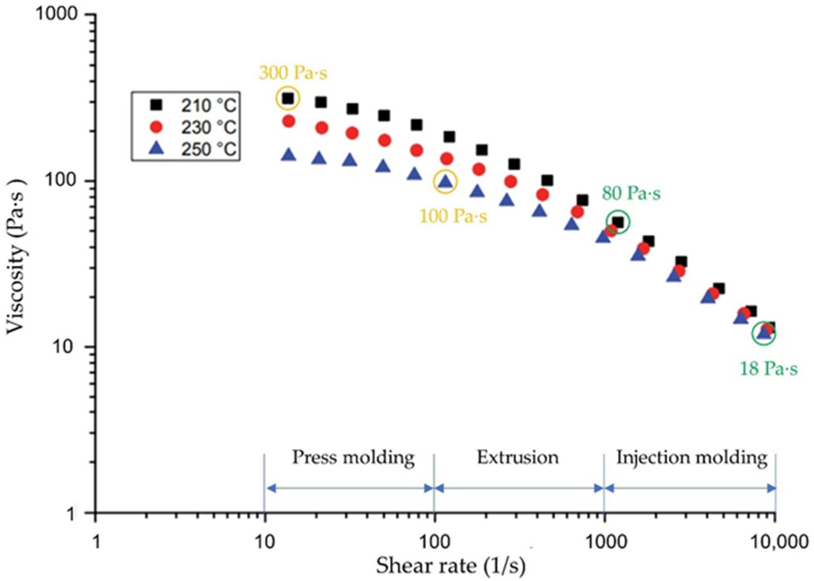
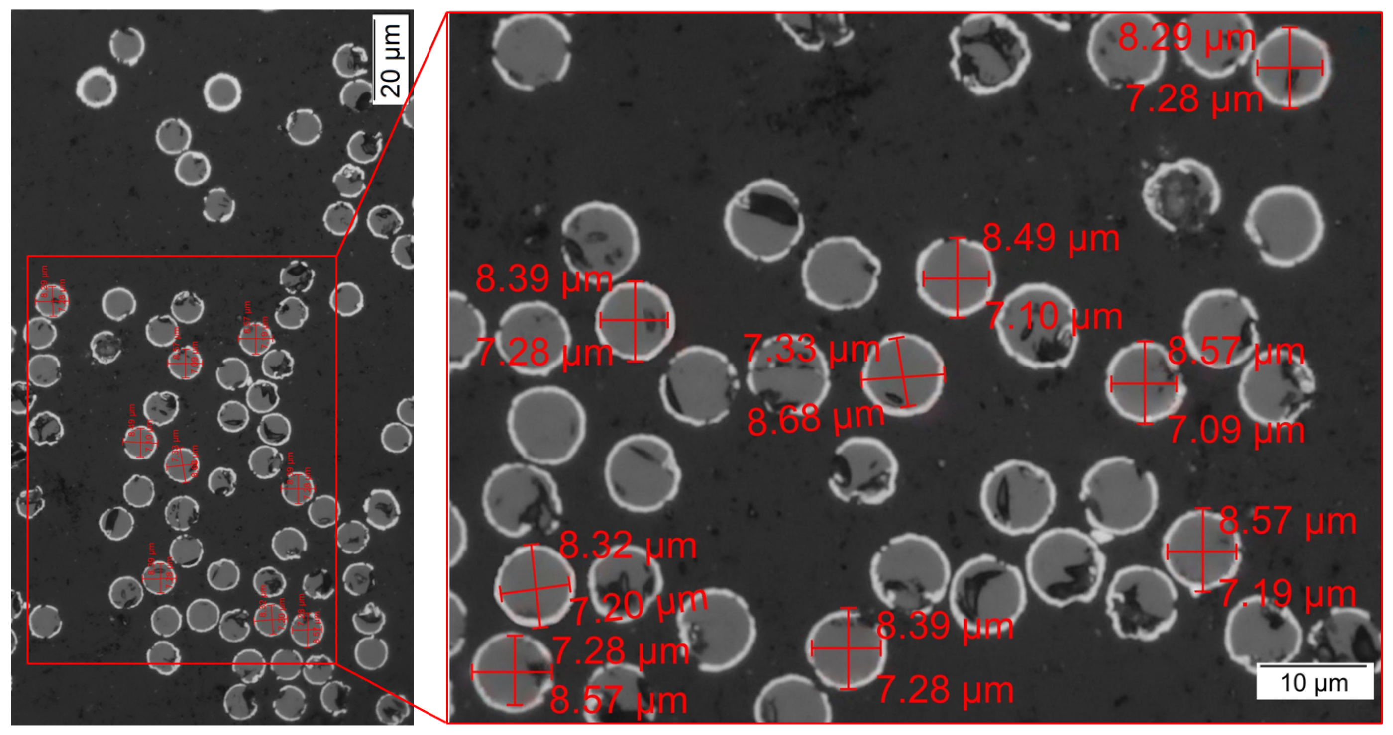
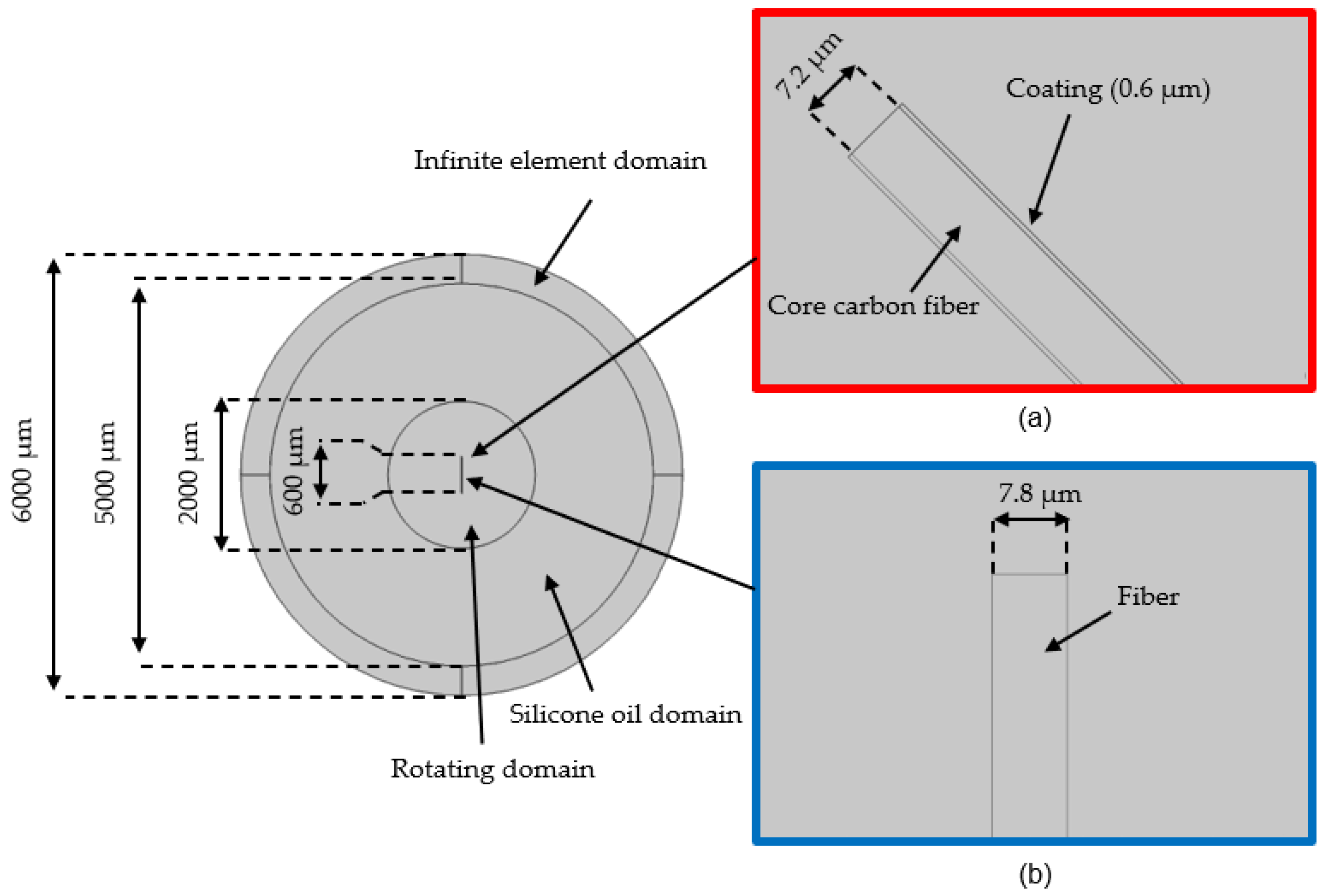
3.1. Material
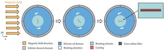
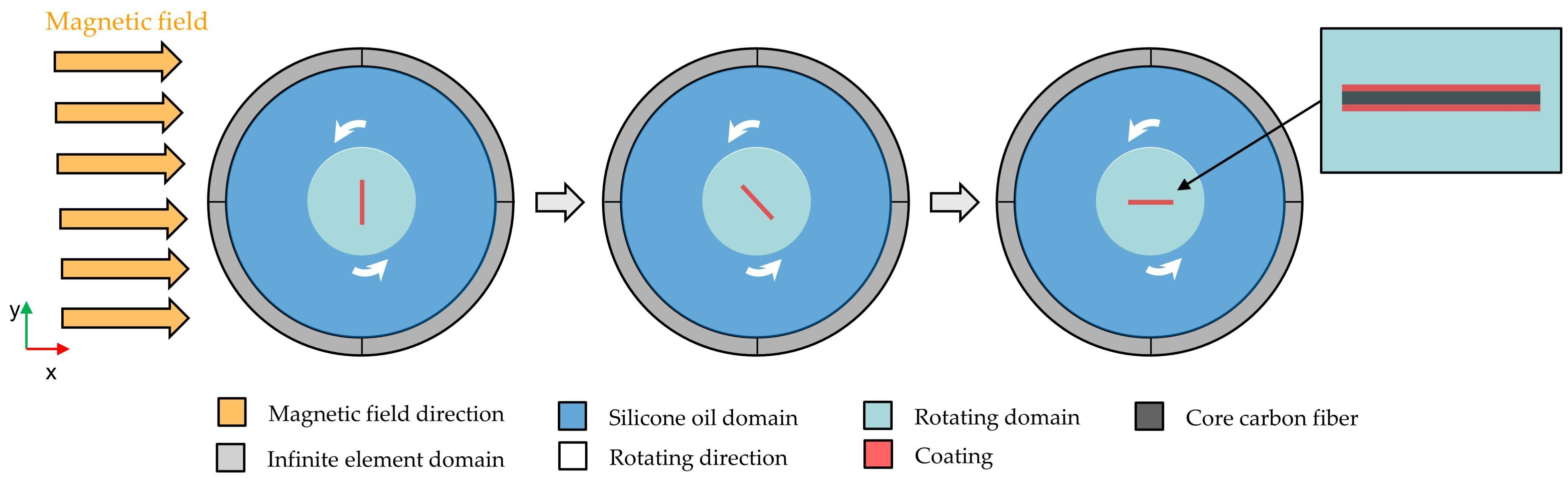
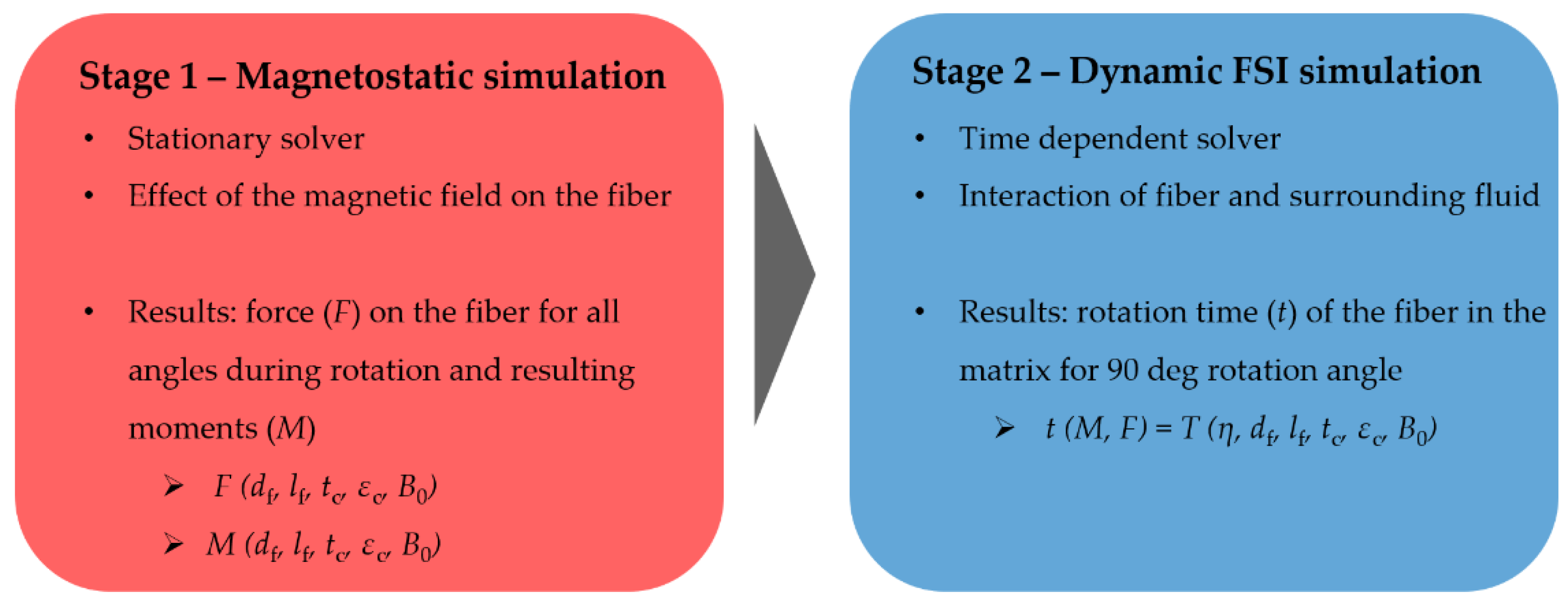
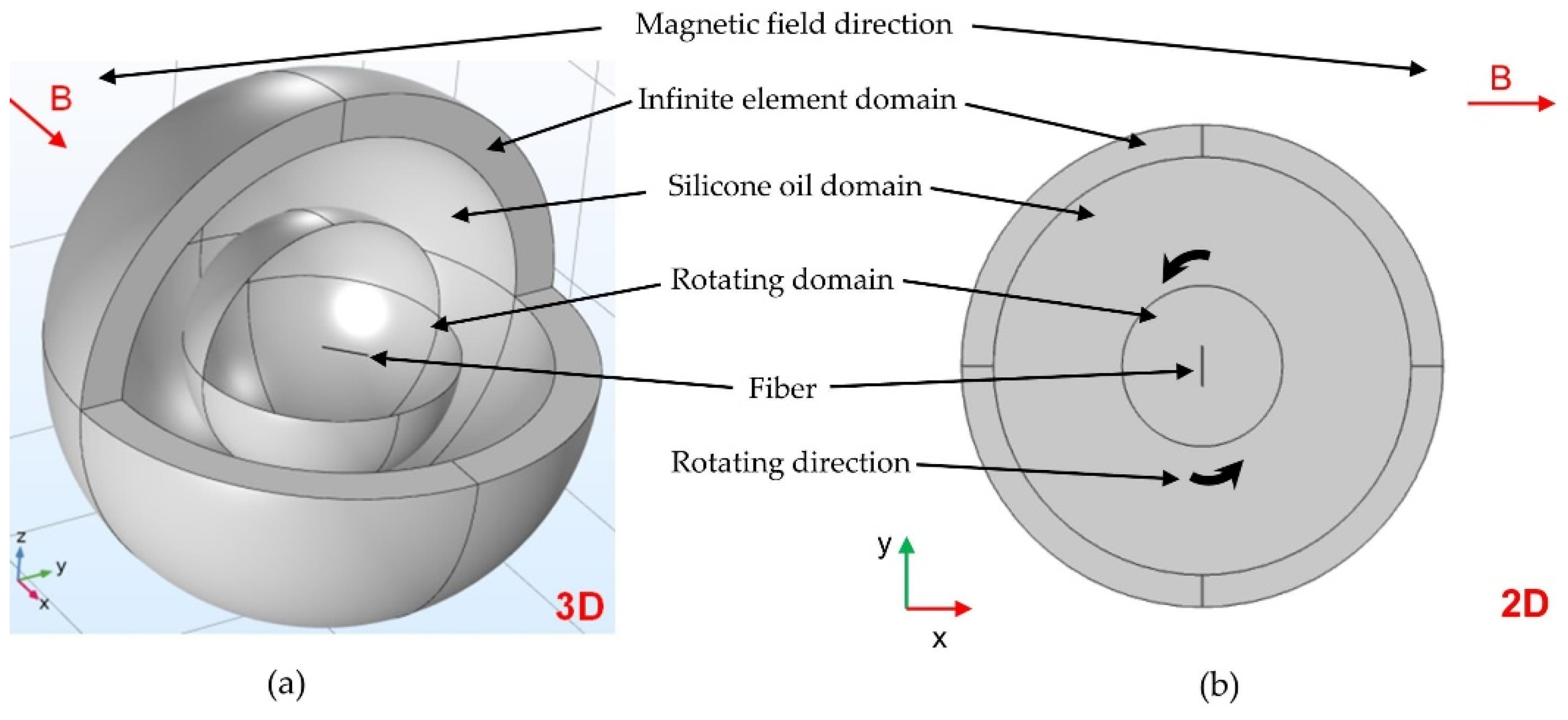
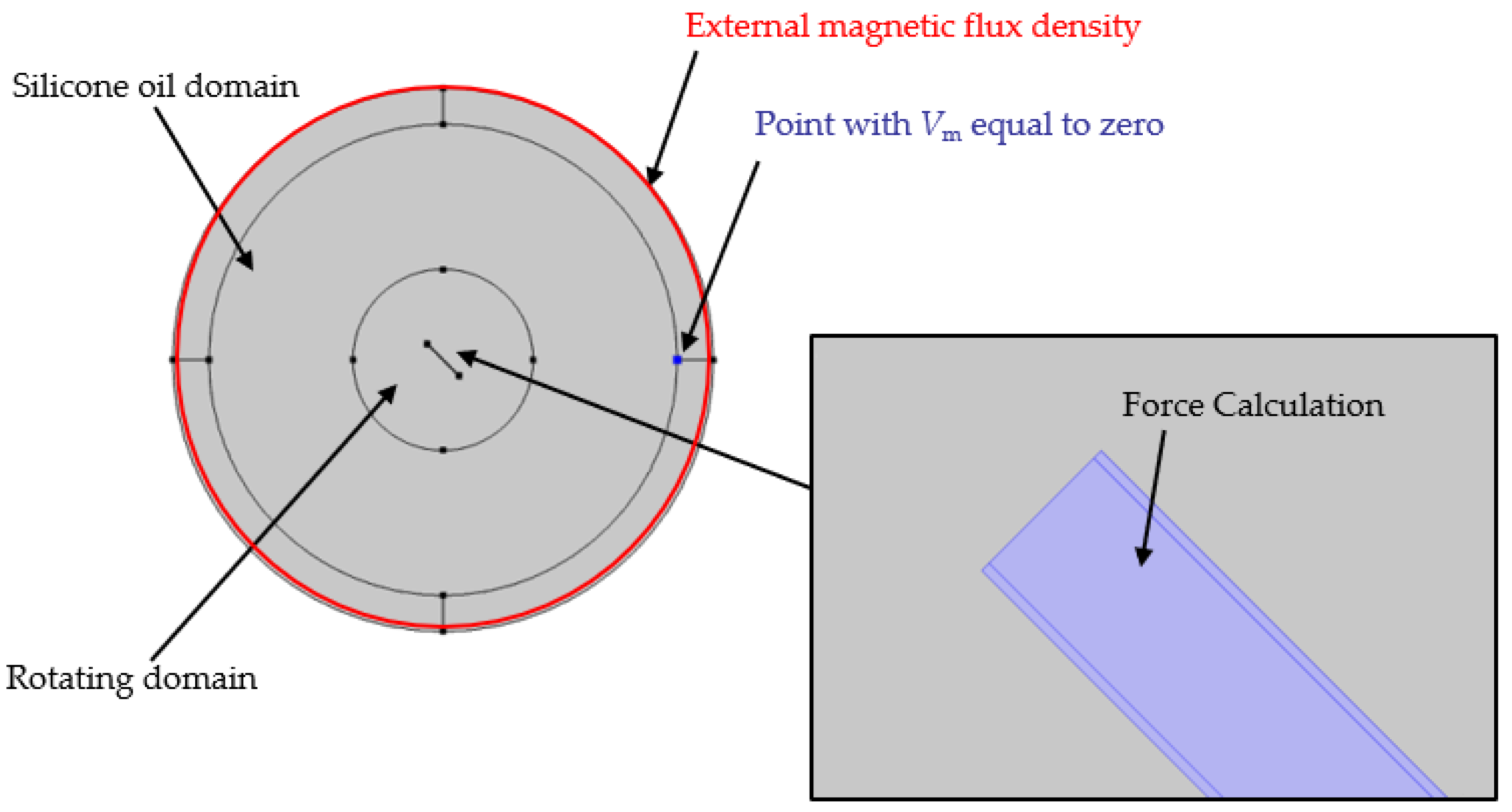
3.2. Simulation Methods
4. Results and Discussion
4.1. Results of the Magnetostatic Simulation
4.2. Results of the Dynamic FSI Simulation
5. Conclusions
Author Contributions
Funding
Institutional Review Board Statement
Informed Consent Statement
Data Availability Statement
Acknowledgments
Conflicts of Interest
Nomenclature
| η | dynamic viscosity |
| µr,c | coating relative permeability |
| µ0 | permeability of vacuum |
| µr | relative permeability |
| ρ | fluid density |
| df | diameter of core carbon fiber |
| t | rotation time |
| tc | coating thickness |
| lf | fiber length |
| B0 | magnetic field/magnetic flux density |
| F | force |
| M | torque |
| B | magnetic flux density |
| H | magnetic field intensity |
| Vm | scalar magnetic potential |
| Hb | magnetic field intensity of the defined background magnetic field |
| n | unit outer-pointing normal of the object |
| T | Maxwell stress tensor |
| S | surface of the object |
| ro | pivot point of rotation |
| rax | the rotation axis |
| u | flow velocity |
| p | fluid pressure |
| I | identity matrix |
| Mext | magnetic torque |
| an | analytical function in COMSOL |
| mod | modulo operation |
| (nx, ny) | normal vector of an edge |
| (nx, ny, nz) | normal vector of a surface |
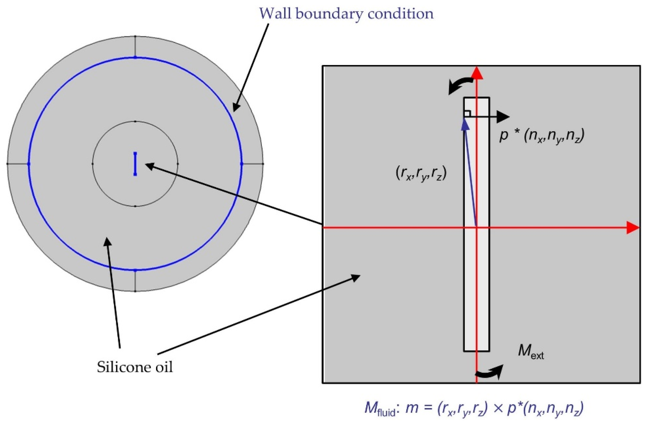
| (rx, ry, rz) | vector from the reference point to the point under consideration |
| f | vector of force density |
| m | surface torque density |
| Mfluid | reaction of the fluid on the fiber |
| intop | integral function in COMSOL |
| thickness | depth of the model |
| TFP | tailored fiber placement |
| NiC | Ni-Coated |
| PDMS | polydimethylsiloxane |
| FEM | finite element method |
| FSI | fluid–structure interaction |
References
- Ahmad, M.S.; Zihilif, A.M.; Martuscelli, E.; Ragosta, G.; Scafora, E. The Electrical Conductivity of Polypropylene and Nickel-Coated Carbon Fiber Composite. Polym. Compos. 1992, 13, 53–57. [Google Scholar] [CrossRef]
- Pishvar, M.; Amirkhosravi, M.; Altan, M. Processing and Alignment of Short Carbon Fibers in an Epoxy Composite by a Magnetic Field. In Proceedings of the Americas Conference of the Polymer Processing Society 2018, Boston, MA, USA, 5–9 November 2018. [Google Scholar]
- Neitzel, M.; Mitschang, P.; Breuer, U. Handbuch Verbundwerkstoffe: Werkstoffe, Verarbeitung, Anwendung; Carl Hanser Verlag GmbH Co KG: Munich, Germany, 2014; pp. 90–91. ISBN 978-3-446-43697-8. [Google Scholar]
- Kim, G.; Shkel, Y.M. Polymeric Composites Tailored by Electric Field. J. Mater. Res. 2004, 19, 1164–1174. [Google Scholar] [CrossRef]
- Ciambella, J.; Stanier, D.C.; Rahatekar, S.S. Magnetic Alignment of Short Carbon Fibres in Curing Composites. Compos. Part B Eng. 2017, 109, 129–137. [Google Scholar] [CrossRef] [Green Version]
- Stanier, D.C.; Ciambella, J.; Rahatekar, S.S. Fabrication and Characterisation of Short Fibre Reinforced Elastomer Composites for Bending and Twisting Magnetic Actuation. Compos. Part Appl. Sci. Manuf. 2016, 91, 168–176. [Google Scholar] [CrossRef] [Green Version]
- Kim, H.C.; Kim, J.W.; Zhai, L.; Kim, J. Strong and Tough Long Cellulose Fibers Made by Aligning Cellulose Nanofibers under Magnetic and Electric Fields. Cellulose 2019, 26, 5821–5829. [Google Scholar] [CrossRef]
- Scholz, M.-S.; Drinkwater, B.W.; Trask, R.S. Ultrasonic Assembly of Anisotropic Short Fibre Reinforced Composites. Ultrasonics 2014, 54, 1015–1019. [Google Scholar] [CrossRef] [PubMed]
- Timbrell, V. Alignment of Carbon and Other Man-made Fibers by Magnetic Fields. J. Appl. Phys. 1972, 43, 4839–4840. [Google Scholar] [CrossRef]
- Chung, C.Y.; Chen, S.C.; Lin, K.J. Effect of Magnetic Field on the Fiber Orientation during the Filling Process in Injection Molding, Part 1: Simulation and Mold Design. Mater. Sci. Forum 2018, 936, 126–135. [Google Scholar] [CrossRef]
- Chen, S.C.; Chung, C.Y.; Tseng, Y.L. Effect of Magnetic Field on the Fiber Orientation during the Filling Process in Injection Molding, Part 2: Experiments and Electrical Conductivity Measurements. Mater. Sci. Forum 2018, 936, 136–141. [Google Scholar] [CrossRef]
- Pishvar, M.; Amirkhosravi, M.; Altan, M.C. Alignment of Nickel Coated Carbon Fibers by Magnetic Field during Cure of Polymer Composites. In Proceedings of the American Society for Composites 2018, Washington, DC, USA, 7 November 2018. [Google Scholar]
- Masuda, S.; Itoh, T. Electrostatic Means for Fabrication of Fiber-Reinforced Metals. IEEE Trans. Ind. Appl. 1989, 25, 552–557. [Google Scholar] [CrossRef]
- Itoh, T.; Masuda, S.; Gomi, F. Electrostatic Orientation of Ceramic Short Fibers in Liquid. J. Electrost. 1994, 32, 71–89. [Google Scholar] [CrossRef]
- Erb, R.M.; Libanori, R.; Rothfuchs, N.; Studart, A.R. Composites Reinforced in Three Dimensions by Using Low Magnetic Fields. Science 2012, 335, 199–204. [Google Scholar] [CrossRef] [PubMed]
- Hatta, H.; Yamashita, S. Fiber Orientation Control by Means of Magnetic Moment. J. Compos. Mater. 1988, 22, 484–500. [Google Scholar] [CrossRef]
- Bordel, D.; Putaux, J.-L.; Heux, L. Orientation of Native Cellulose in an Electric Field. Langmuir 2006, 22, 4899–4901. [Google Scholar] [CrossRef] [PubMed]
- Takeyama, S.; Nakamura, S.; Uchida, K. Dynamical Orientation of Carbon Nanotubes by Pulsed Magnetic Fields. J. Phys. Conf. Ser. 2006, 51, 446–449. [Google Scholar] [CrossRef]
- Lu, G.; Li, X.; Jiang, H. Electrical and Shielding Properties of ABS Resin Filled with Nickel-Coated Carbon Fibers. Compos. Sci. Technol. 1996, 56, 193–200. [Google Scholar] [CrossRef]
- Kimura, T. Study on the Effect of Magnetic Fields on Polymeric Materials and Its Application. Polym. J. 2003, 35, 823–843. [Google Scholar] [CrossRef]
- DIN 54811-1984-05-Beuth. Available online: https://www.beuth.de/de/norm/din-54811/1118726 (accessed on 20 April 2020).
- Littek, S.; Schneider, M. Messung zum Materialabbau von Polypropylen. J. Plast. Technol. 2012, 8, 415–438. [Google Scholar]
- QUAX GmbH. Datasheet: Eigenschaften der Standardviskosität; QUAX GmbH: Otzberg, Germany, 2018. [Google Scholar]
- Zhang, L.-Z.; Wang, X.-J.; Quan, Y.-Y.; Pei, L.-X. Conjugate Heat Conduction in Filled Composite Materials Considering Interactions between the Filler and Base Materials. Int. J. Heat Mass Transf. 2013, 64, 735–742. [Google Scholar] [CrossRef]
- Hajjari, E.; Divandari, M.; Mirhabibi, A. The Study of Electroless Coating of Nickel on Carbon Fibers. Iran. J. Mater. Sci. Eng. 2004, 1, 43–48. [Google Scholar]
- Vaccumschmelze GmbH. Datasheet: Soft Magnetic Cobalt-Iron Alloys; Vaccumschmelze GmbH: Hanau, Germany, 2021; Available online: https://vacuumschmelze.com/shared/quickNav/Downloads (accessed on 4 November 2021).
- Sharma, D. Pure Iron and Low Carbon Steels—Soft Magnetic P/M Materials. J. Chem. Pharm. Res. 2017, 9, 225–229. [Google Scholar]
- Pozo, B.; Garate, J.I.; Araujo, J.Á.; Ferreiro, S. Energy Harvesting Technologies and Equivalent Electronic Structural Models—Review. Electronics 2019, 8, 486. [Google Scholar] [CrossRef] [Green Version]
- Chung, D.D. Applied Materials Science: Applications of Engineering Materials in Structural, Electronics, Thermal, and Other Industries; CRC Press: Boca Raton, FL, USA, 2001. [Google Scholar] [CrossRef]
- Paul, C.R. Introduction to Electromagnetic Compatibility, 2nd ed.; Wiley-Interscience: Hoboken, NJ, USA, 2006; ISBN 978-0-471-75500-5. [Google Scholar]
- Schürmann, H. Konstruieren mit Faser-Kunststoff-Verbunden, 2nd ed.; VDI-Buch; Springer: Berlin/Heidelberg, Germany, 2007; pp. 137–138. ISBN 978-3-540-72189-5. [Google Scholar]


| Designation | Product Name | Density at 25 °C [g/cm3] | Kinematic Viscosity [cst] | Dynamic Viscosity [Pa·s] |
|---|---|---|---|---|
| S1 | ELBESIL SILIKONÖL B 12.500 | 0.97 | 12,500 | 12.125 |
| S2 | ELBESIL SILIKONÖL B 20.000 | 0.97 | 20,000 | 19.4 |
| S3 | ELBESIL SILIKONÖL B 30.000 | 0.97 | 30,000 | 29.1 |
| S4 | ELBESIL SILIKONÖL B 40.000 | 0.97 | 40,000 | 38.8 |
| S5 | ELBESIL SILIKONÖL B 60.000 | 0.97 | 60,000 | 58.2 |
| S6 | ELBESIL SILIKONÖL B 80.000 | 0.98 | 80,000 | 77.6 |
| S7 | SILIKONÖL AK 100.000 | 0.98 | 100,000 | 97 |
| S8 | SILIKONÖL AK 200.000 | 0.98 | 200,000 | 194 |
| S9 | SILIKONÖL AK 300.000 | 0.98 | 300,000 | 291 |
| Coating Material | Relative Permeability | Reference |
|---|---|---|
| Cobalt–Iron * | 18,000 | [26] |
| Iron * | 5000 | [27] |
| Steel | 100 | [28] |
| Nickel * | 100–600 | [29,30] |
| Copper | 1 | [30] |
| Parameter | Unit | Range of Values |
|---|---|---|
| Viscosity (η) | Pa·s | 12; 20; 30; 40; 60; 80; 100; 200; 300 |
| Diameter of core carbon fiber (df) | μm | 7.2 |
| Coating relative permeability (µr,c) | - | 500, 5000, 18,000 |
| Coating thickness (tc) | μm | 0.2; 0.4; 0.6; 0.8; 1 |
| Fiber length (lf) | μm | 200; 400; 600; 800; 1000; 2000; 4000; 6000; 8000; 10,000 |
| Magnetic field/Magnetic flux density (B0) | mT | 20; 40; 60; 80; 100; 200; 400; 600; 800; 1000 |
Publisher’s Note: MDPI stays neutral with regard to jurisdictional claims in published maps and institutional affiliations. |
© 2022 by the authors. Licensee MDPI, Basel, Switzerland. This article is an open access article distributed under the terms and conditions of the Creative Commons Attribution (CC BY) license (https://creativecommons.org/licenses/by/4.0/).
Share and Cite
Winkler, A.; Modler, N.; Gude, M.; Xu, Y.; Helwig, M.; Dohmen, E.; Dittes, A.; Höhlich, D.; Lampke, T. Numerical Investigation of the Orientability of Single Reinforcement Fibers in Polymer Matrices. Polymers 2022, 14, 534. https://doi.org/10.3390/polym14030534
Winkler A, Modler N, Gude M, Xu Y, Helwig M, Dohmen E, Dittes A, Höhlich D, Lampke T. Numerical Investigation of the Orientability of Single Reinforcement Fibers in Polymer Matrices. Polymers. 2022; 14(3):534. https://doi.org/10.3390/polym14030534
Chicago/Turabian StyleWinkler, Anja, Niels Modler, Maik Gude, Yun Xu, Martin Helwig, Eike Dohmen, Axel Dittes, Dominik Höhlich, and Thomas Lampke. 2022. "Numerical Investigation of the Orientability of Single Reinforcement Fibers in Polymer Matrices" Polymers 14, no. 3: 534. https://doi.org/10.3390/polym14030534