Author Contributions
Conceptualization, M.T. and V.V.S.; methodology, M.T., I.V. and V.V.S.; validation, I.V.; formal analysis, I.V. and Y.P.; investigation, I.V.; writing—original draft preparation, I.V. and Y.P.; writing—review and editing, M.T. and V.V.S.; visualization, I.V. and Y.P.; supervision, V.V.S.; project administration, M.T.; funding acquisition, M.T. and V.V.S. All authors have read and agreed to the published version of the manuscript.
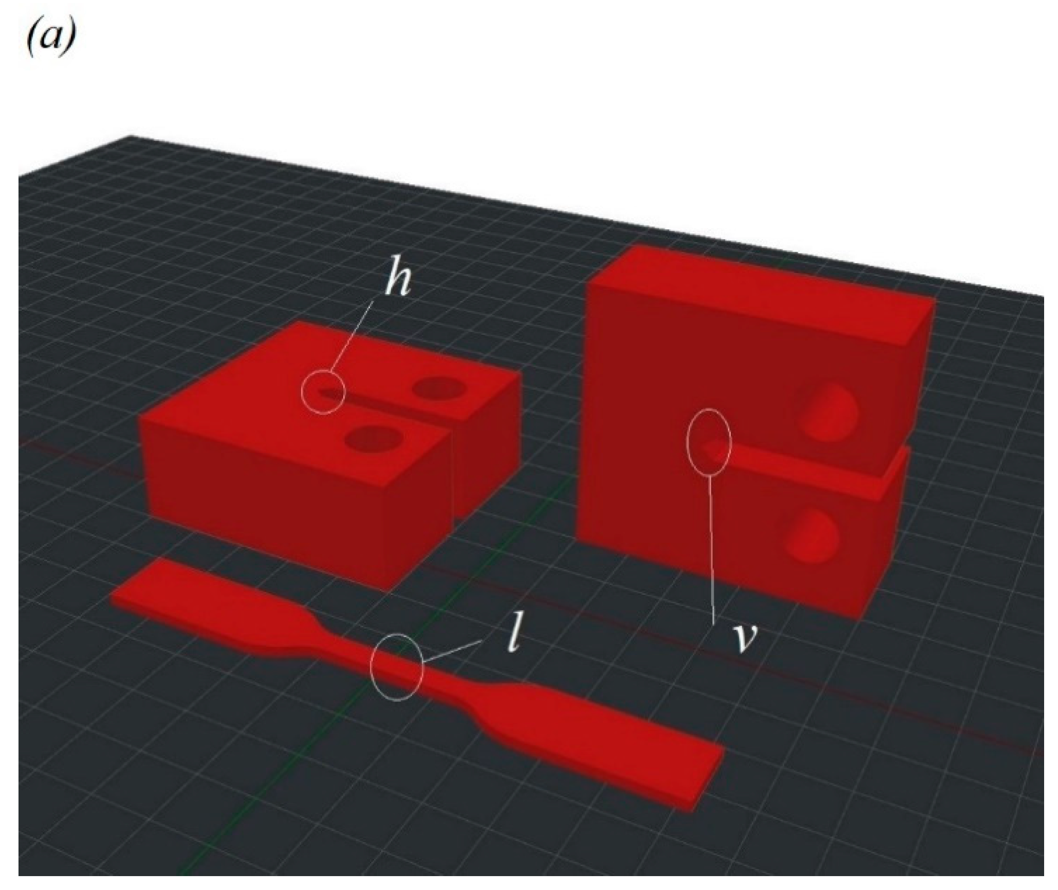
Figure 1.
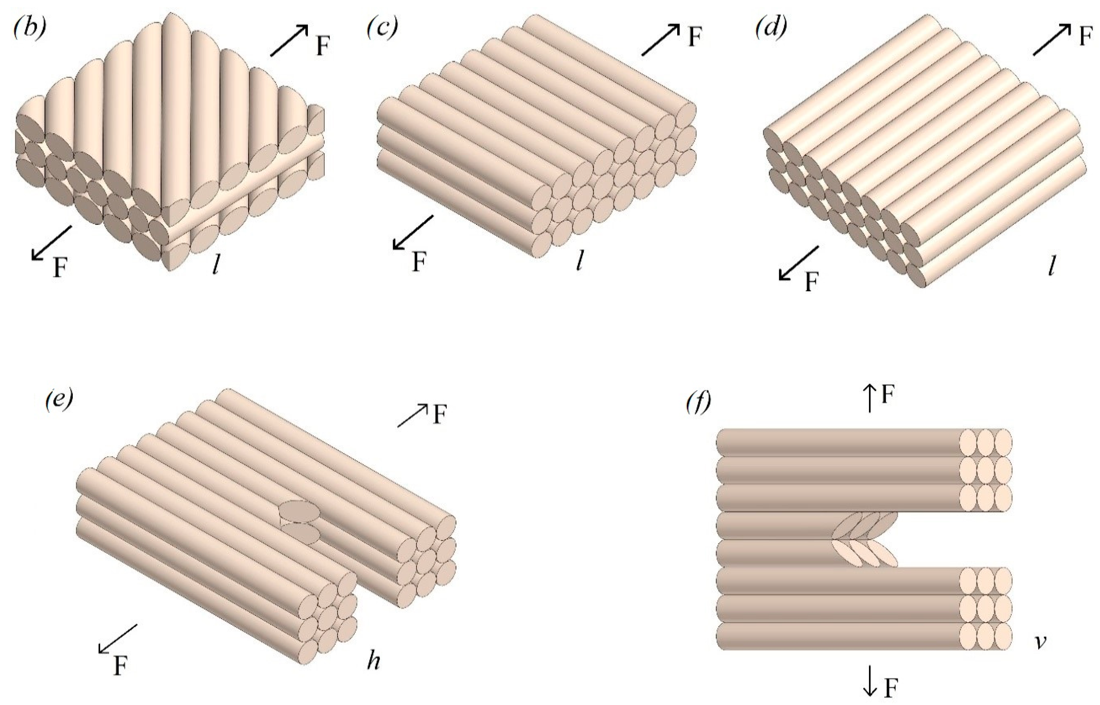
(a) Geometry of FFF manufactured PEEK samples for tensile and CT tests. Printing scheme for tensile samples for three configurations of infill angle: (b) °, (c) 90° and (d) 180°. Configuration of the CT samples: (e) horizontal orientation h, (f) vertical orientation v.
Figure 1.
(a) Geometry of FFF manufactured PEEK samples for tensile and CT tests. Printing scheme for tensile samples for three configurations of infill angle: (b) °, (c) 90° and (d) 180°. Configuration of the CT samples: (e) horizontal orientation h, (f) vertical orientation v.
Figure 2.
(a) Geometry of standard tensile test sample. PEEK sample without (b) and with (c) heat treatment.
Figure 2.
(a) Geometry of standard tensile test sample. PEEK sample without (b) and with (c) heat treatment.
Figure 3.
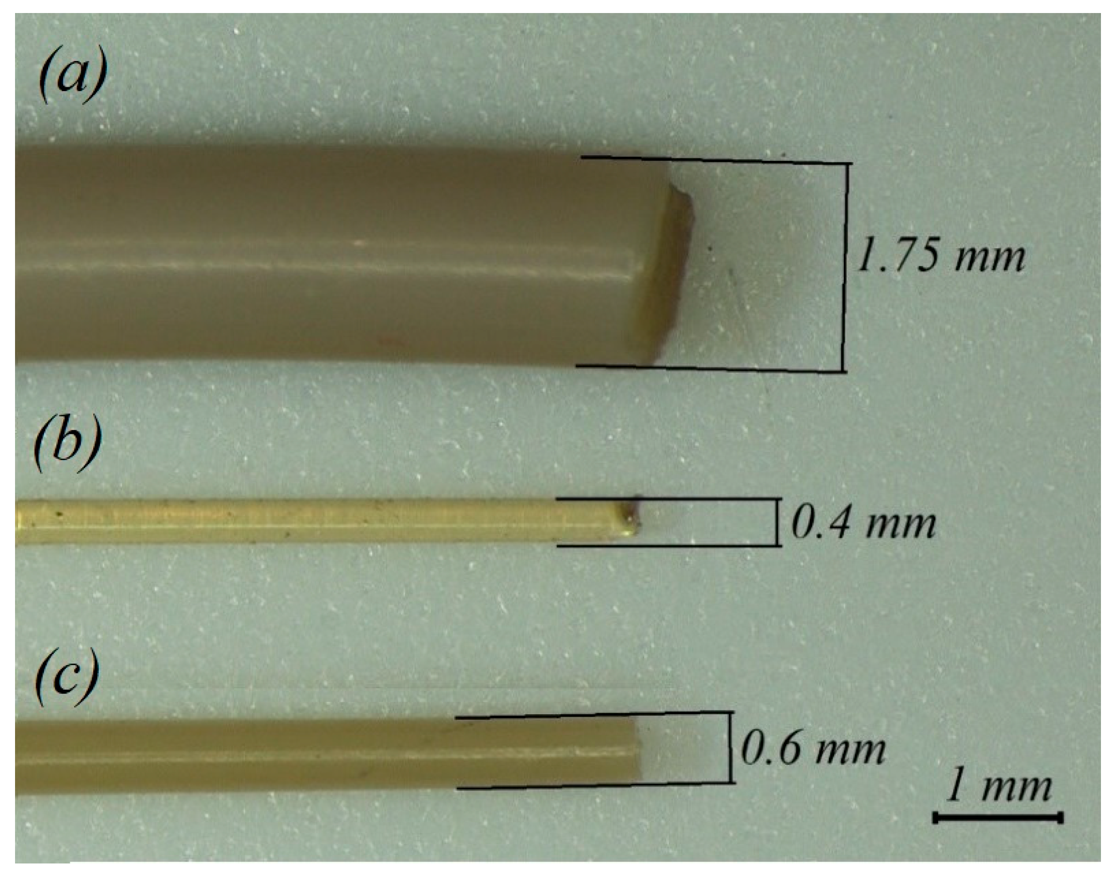
(a) As-delivered filament from coil; (b) filament extruded via 0.4 mm nozzle before heat treatment; and (c) filament extruded via 0.6 mm nozzle after heat treatment.
Figure 3.
(a) As-delivered filament from coil; (b) filament extruded via 0.4 mm nozzle before heat treatment; and (c) filament extruded via 0.6 mm nozzle after heat treatment.
Figure 4.
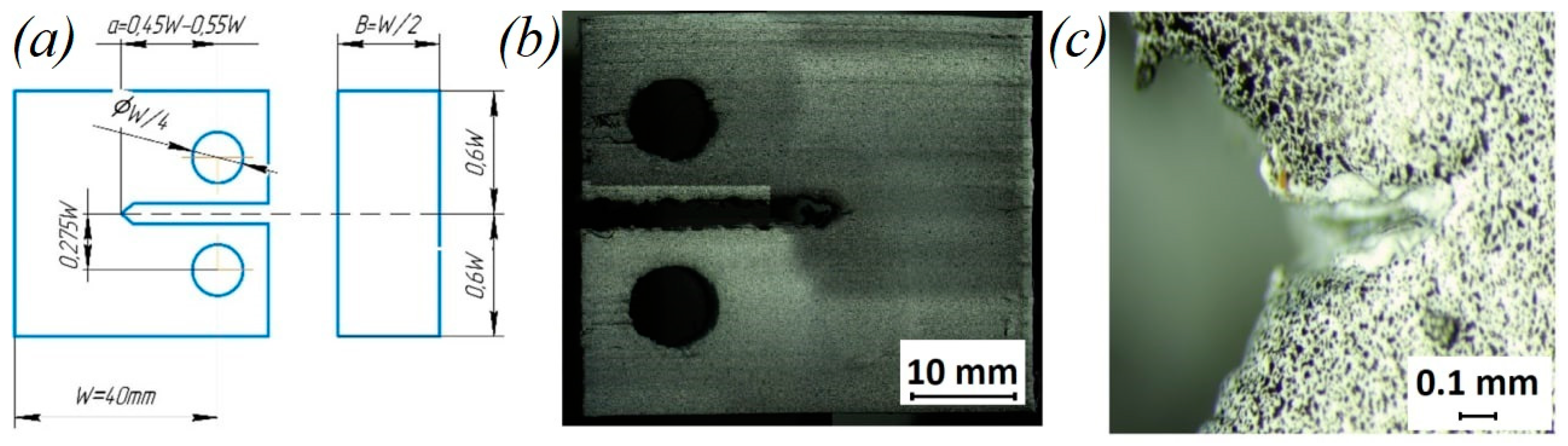
(a) Geometry of CT sample; (b) PEEK CT sample with speckles; and (c) enlarged view of crack is sharp edge area of sample.
Figure 4.
(a) Geometry of CT sample; (b) PEEK CT sample with speckles; and (c) enlarged view of crack is sharp edge area of sample.
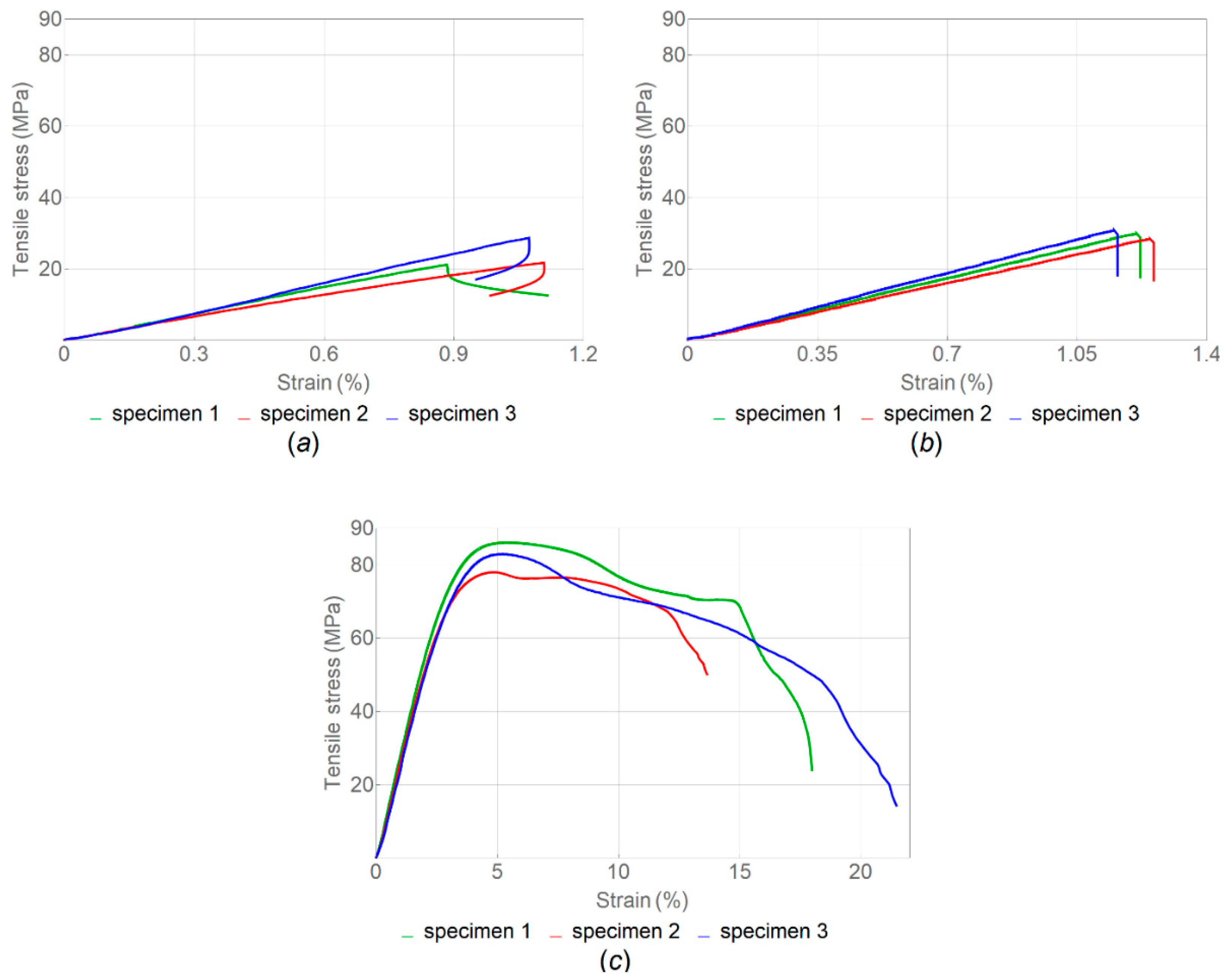
Figure 5.
Stress–strain curve for tension load of samples without heat treatment with different infill angle α: (a) 45°; (b) 90°; and (c) 180° (nozzle diameter, 0.6 mm).
Figure 5.
Stress–strain curve for tension load of samples without heat treatment with different infill angle α: (a) 45°; (b) 90°; and (c) 180° (nozzle diameter, 0.6 mm).
Figure 6.
Results for tensile strength and elastic modulus of samples without heat treatment for α = 45°, α = 90° and α = 180° (nozzle diameter is given in brackets).
Figure 6.
Results for tensile strength and elastic modulus of samples without heat treatment for α = 45°, α = 90° and α = 180° (nozzle diameter is given in brackets).
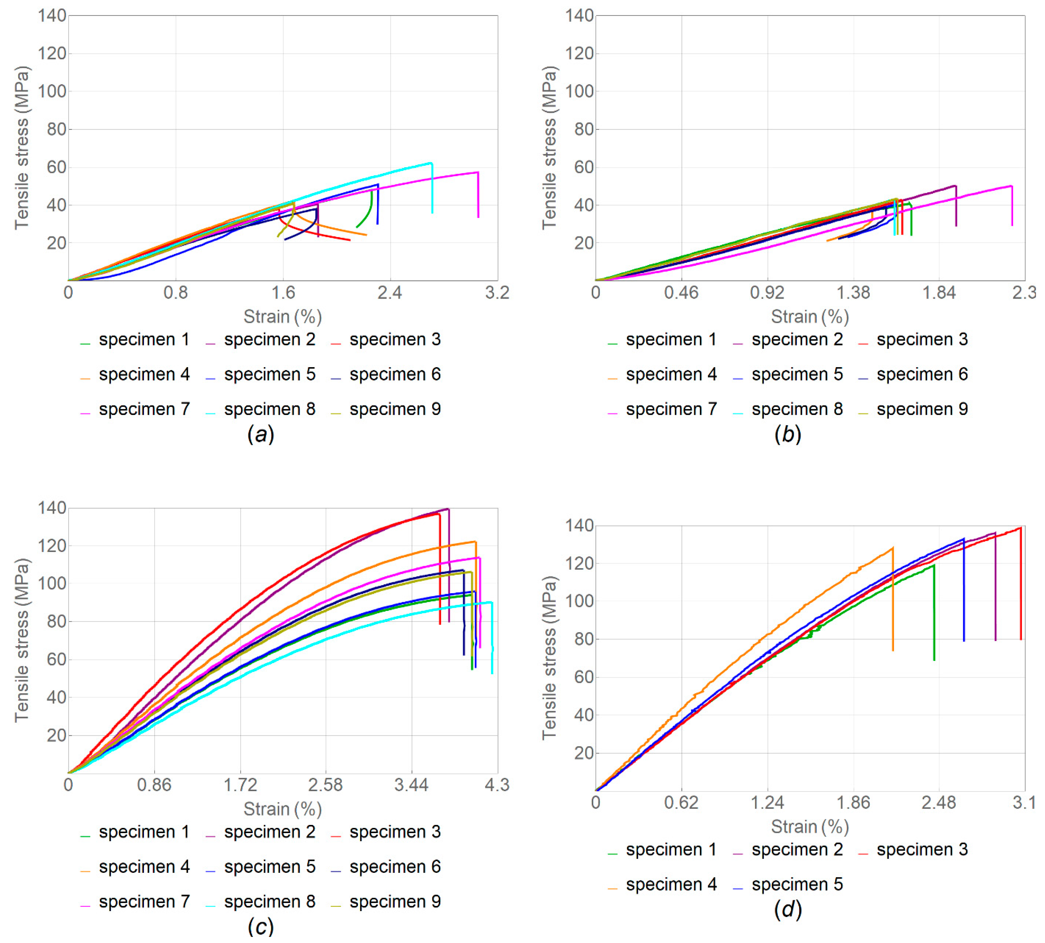
Figure 7.
Tensile stress–strain curves for samples after heat treatment with different infill angle α: (a) 45°; (b) 90°; (c) 180°; and (d) 180° (nozzle diameter, 0.4 mm in (d) and 0.6 mm in (a–c)).
Figure 7.
Tensile stress–strain curves for samples after heat treatment with different infill angle α: (a) 45°; (b) 90°; (c) 180°; and (d) 180° (nozzle diameter, 0.4 mm in (d) and 0.6 mm in (a–c)).
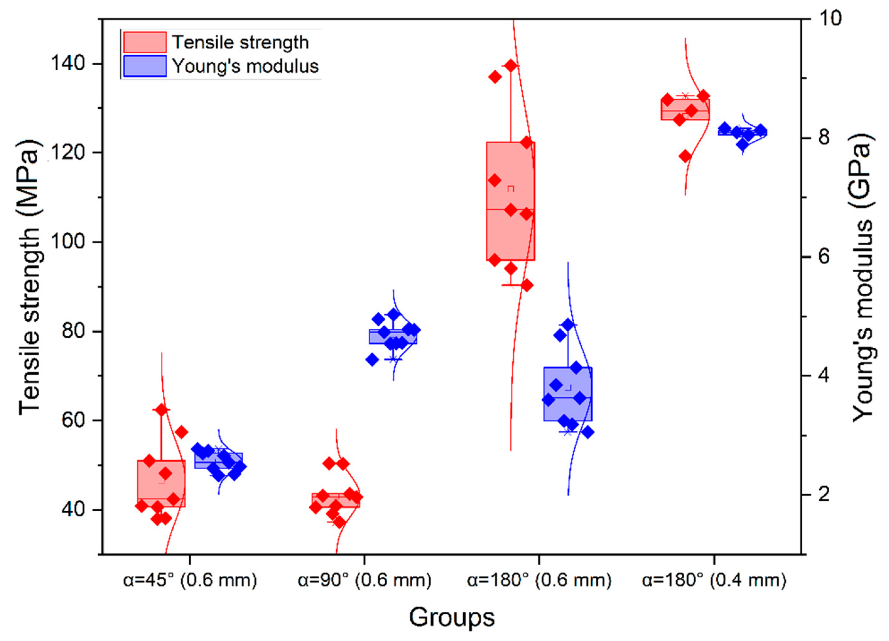
Figure 8.
Results for tensile strength and elastic modulus of heat-treated samples for α = 45°, α = 90° and α = 180°.
Figure 8.
Results for tensile strength and elastic modulus of heat-treated samples for α = 45°, α = 90° and α = 180°.
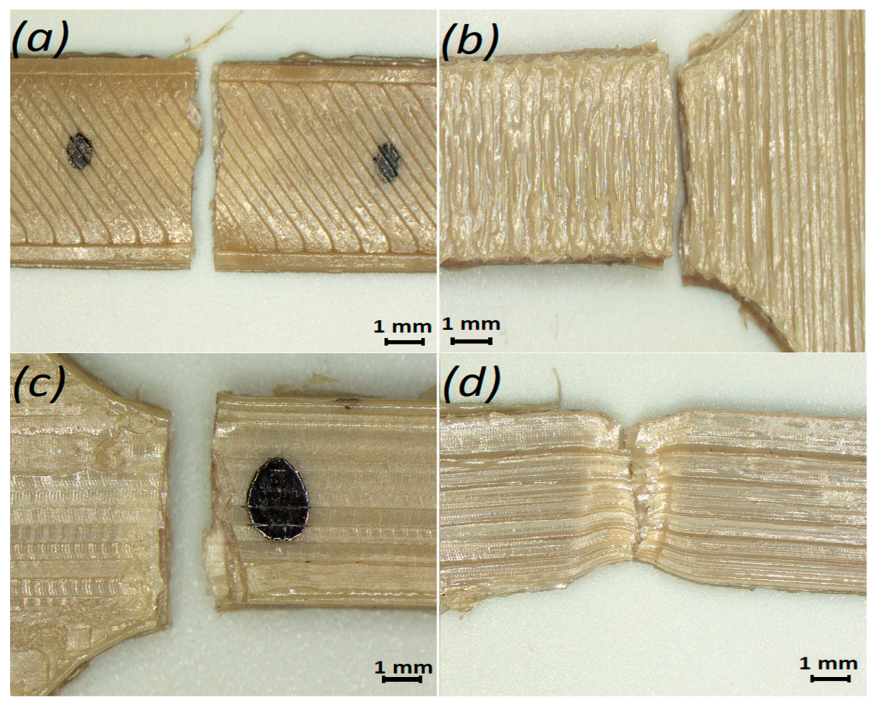
Figure 9.
Fractured samples with different infill angles α: (a) 45°; (b) 90°; (c) 180° with heat treatment; and (d) 180° without heat treatment.
Figure 9.
Fractured samples with different infill angles α: (a) 45°; (b) 90°; (c) 180° with heat treatment; and (d) 180° without heat treatment.
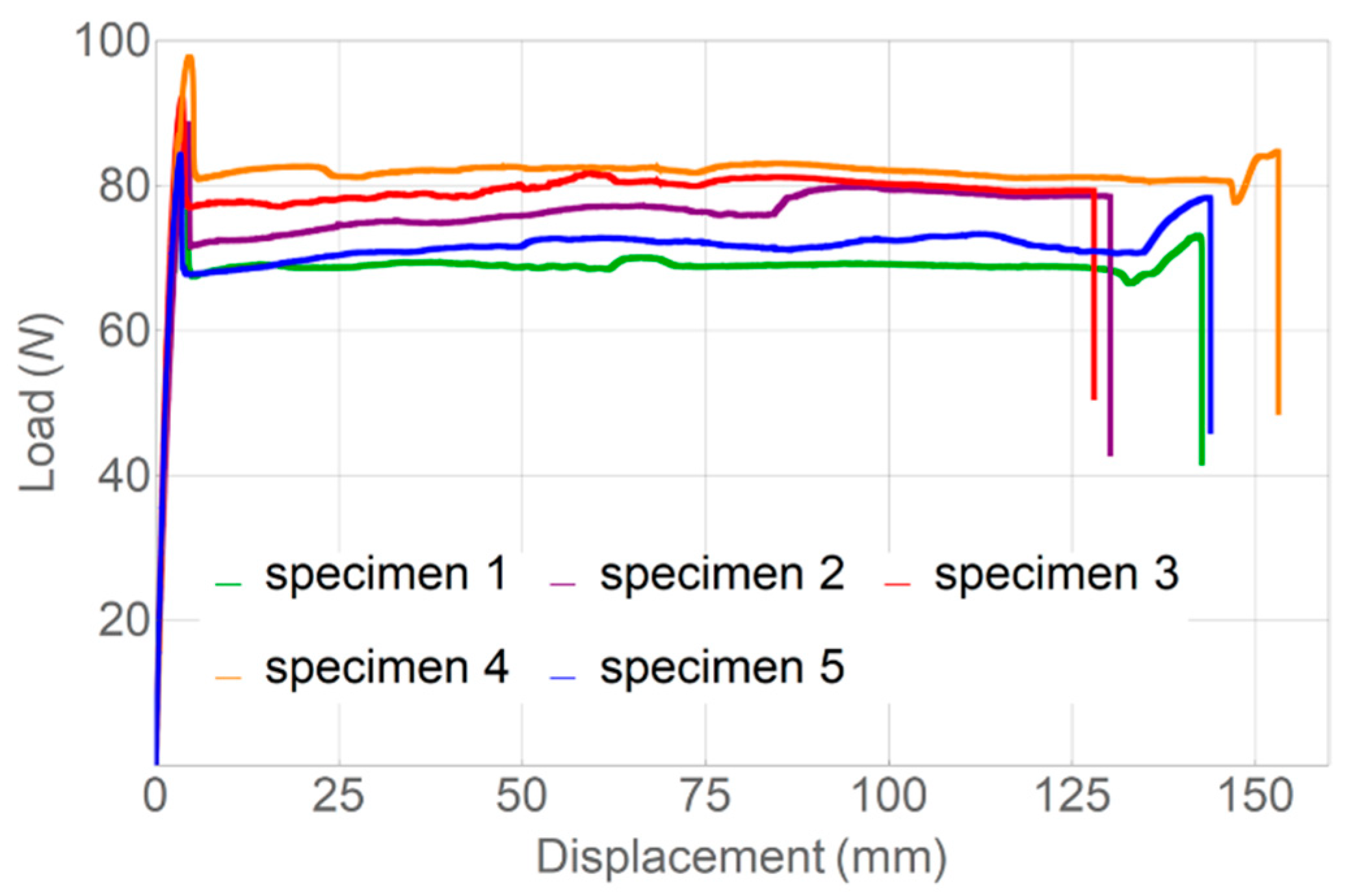
Figure 10.
Stress–strain diagrams for as-delivered filament.
Figure 10.
Stress–strain diagrams for as-delivered filament.
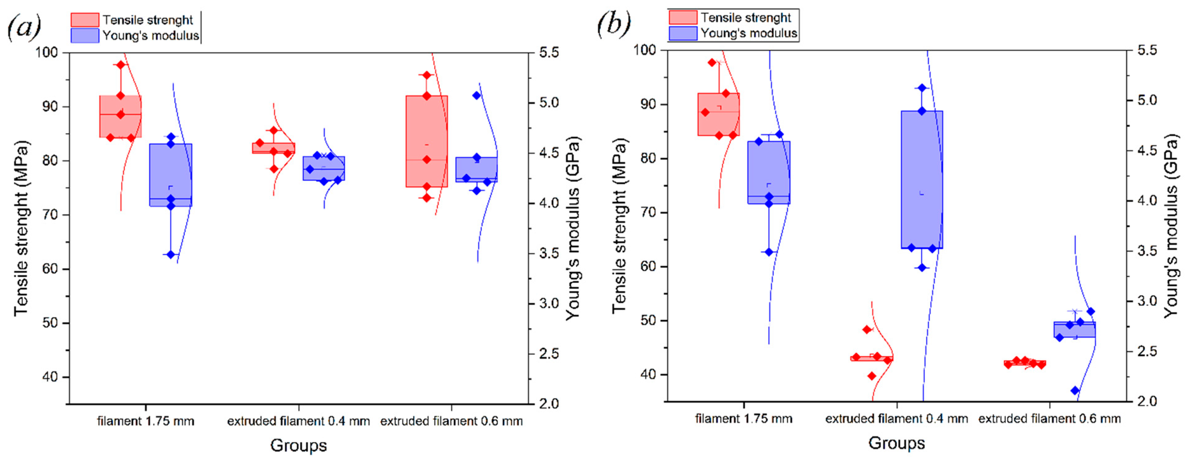
Figure 11.
Results for ultimate strength and modulus of elasticity from tensile tests for as-delivered and extruded filament: (a) with heat treatment and (b) without heat treatment.
Figure 11.
Results for ultimate strength and modulus of elasticity from tensile tests for as-delivered and extruded filament: (a) with heat treatment and (b) without heat treatment.
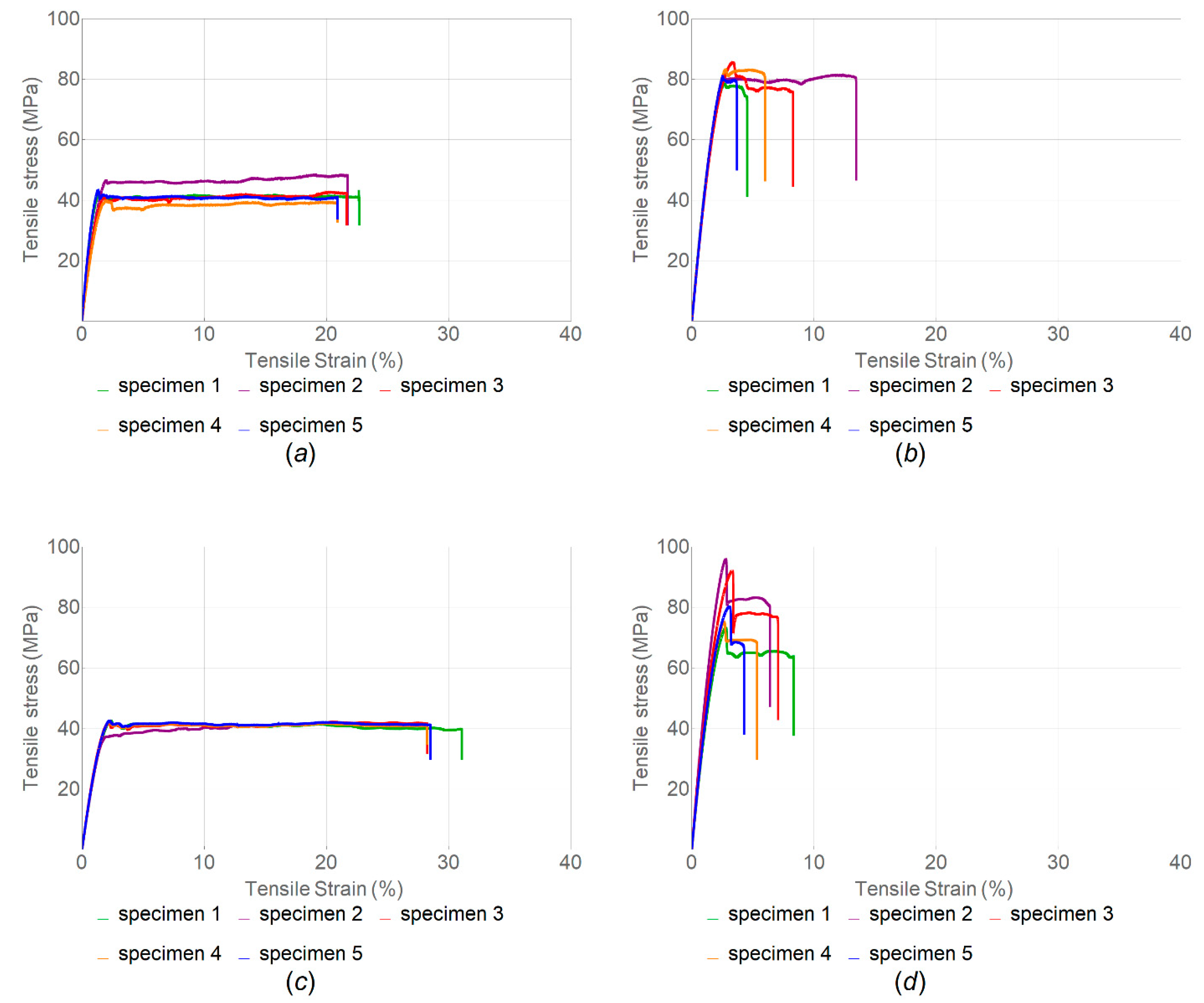
Figure 12.
Stress–strain diagrams for extruded filament printed with (b,d) and without (a,c) heat treatment, ((a,b)—0.4 mm nozzle; (c,d)—0.6 mm nozzle).
Figure 12.
Stress–strain diagrams for extruded filament printed with (b,d) and without (a,c) heat treatment, ((a,b)—0.4 mm nozzle; (c,d)—0.6 mm nozzle).
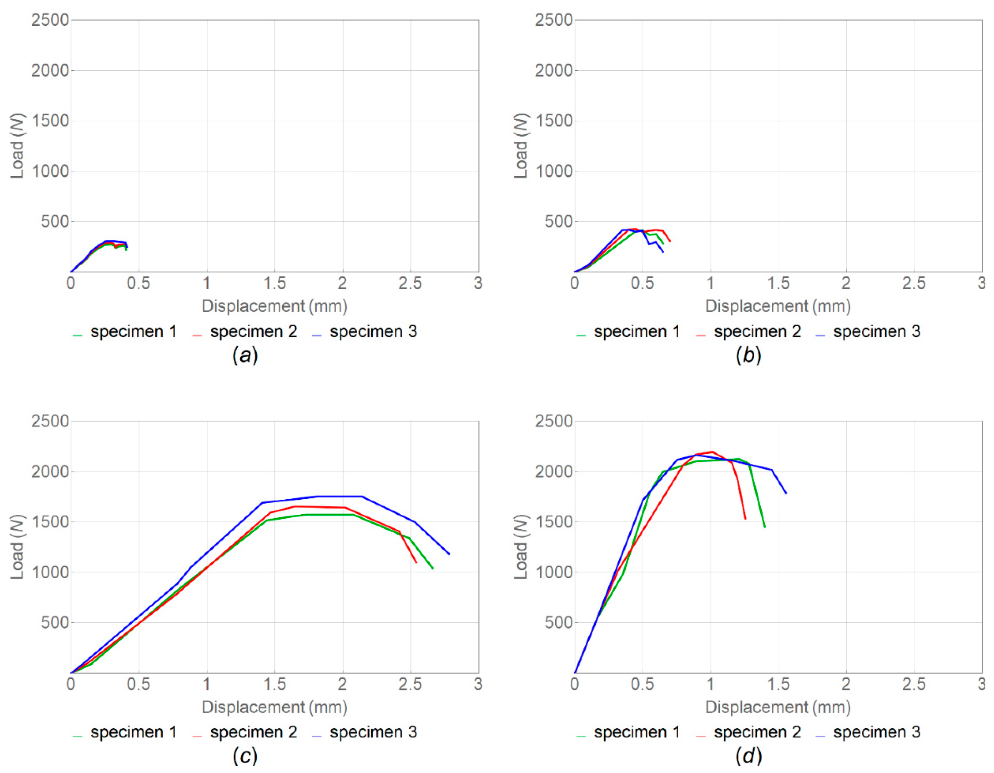
Figure 13.
Load–displacement curves for PEEK samples printed with vertical (a,b) and horizontal (c,d) orientations ((a,c)—no heat treatment; (b,d)—with heat treatment; and infill angle—90°).
Figure 13.
Load–displacement curves for PEEK samples printed with vertical (a,b) and horizontal (c,d) orientations ((a,c)—no heat treatment; (b,d)—with heat treatment; and infill angle—90°).
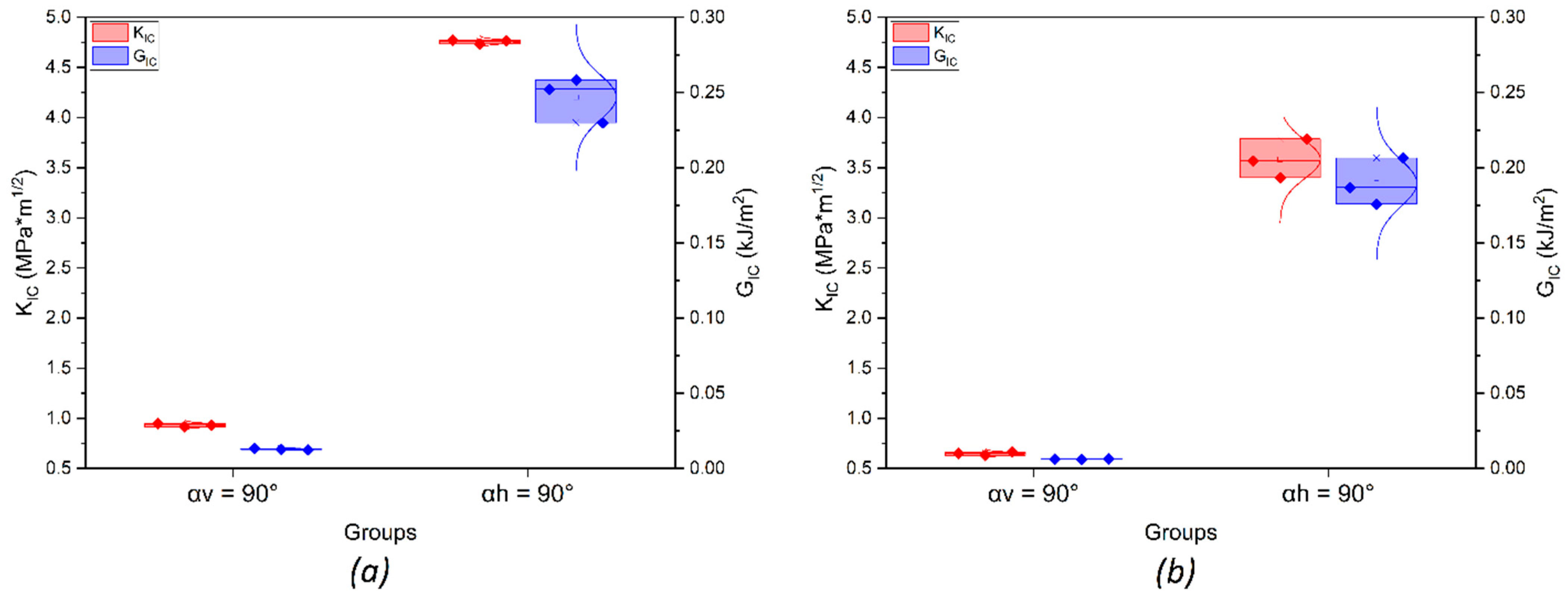
Figure 14.
Results for stress intensity factor and critical strain energy release rate for samples with (a) and without (b) heat treatment.
Figure 14.
Results for stress intensity factor and critical strain energy release rate for samples with (a) and without (b) heat treatment.
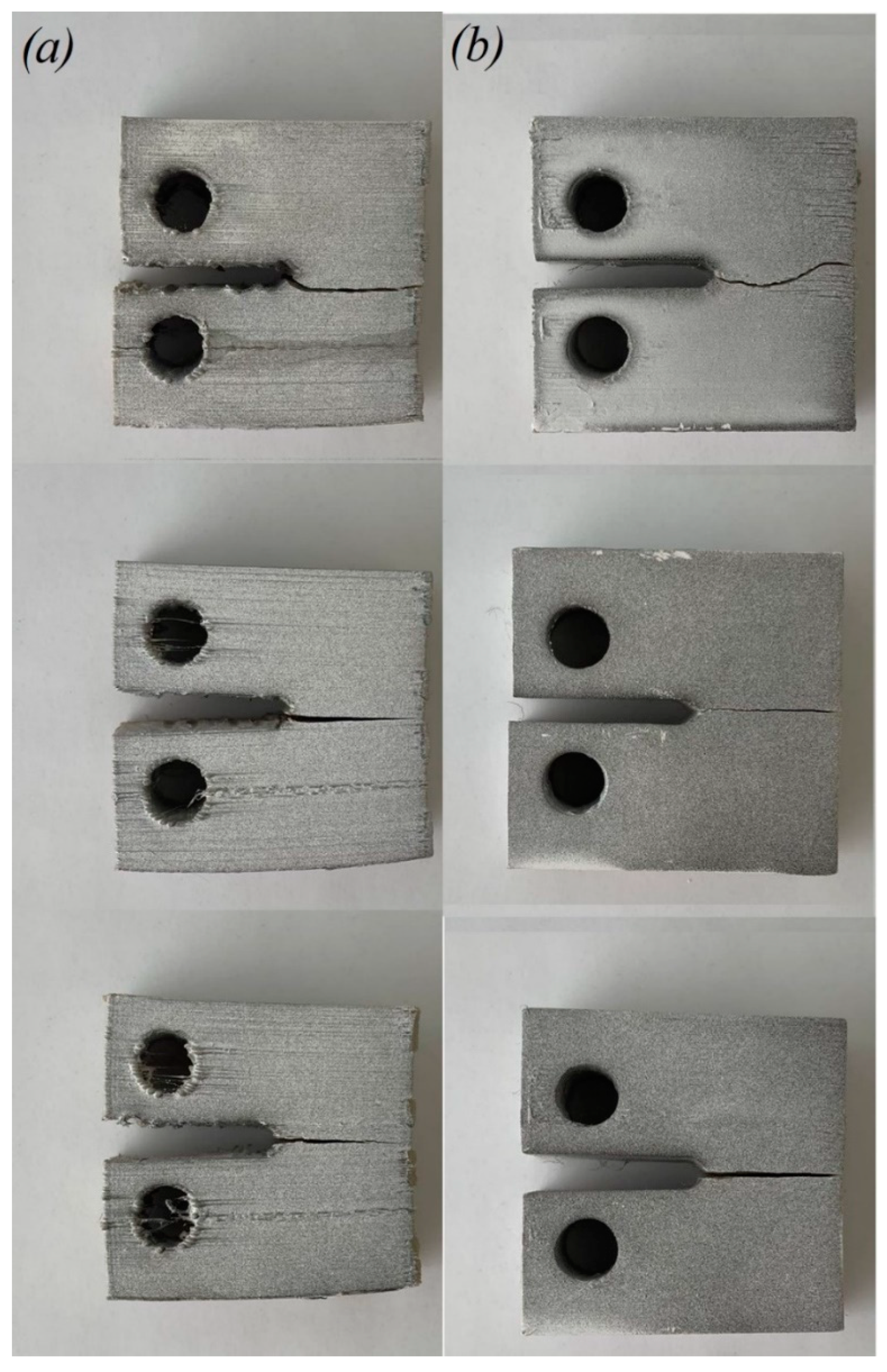
Figure 15.
Fractured CT samples printed with vertical (a) and horizontal (b) orientations.
Figure 15.
Fractured CT samples printed with vertical (a) and horizontal (b) orientations.
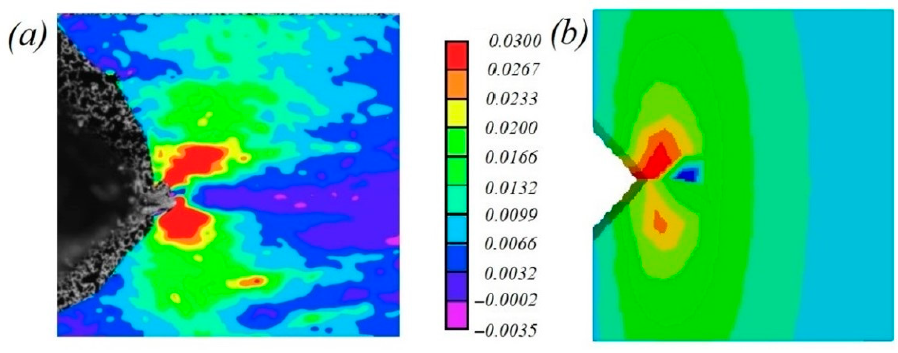
Figure 16.
(a) Axial strains obtained using micro-DIC for heat-treated sample with horizontal orientation at maximum load value; (b) FE analysis performed in Abaqus CAE for same load.
Figure 16.
(a) Axial strains obtained using micro-DIC for heat-treated sample with horizontal orientation at maximum load value; (b) FE analysis performed in Abaqus CAE for same load.
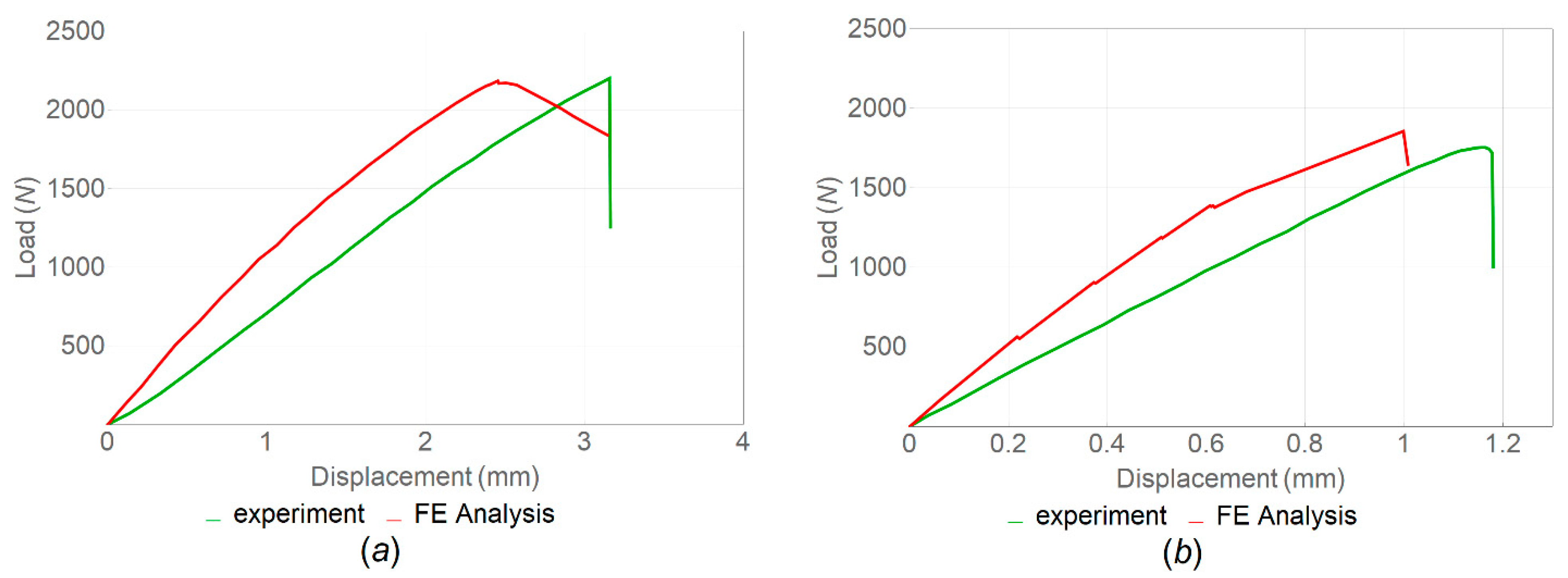
Figure 17.
Load–displacements curves obtained from FE analysis and the experiments for samples with (a) and without (b) heat treatment.
Figure 17.
Load–displacements curves obtained from FE analysis and the experiments for samples with (a) and without (b) heat treatment.
Table 1.
Manufacturing parameters.
Table 1.
Manufacturing parameters.
| Process Parameter | Value |
|---|
| Nozzle movement speed, mm/min | 2100 |
| Nozzle temperature, °C | 435 |
| Table temperature, °C | 145 |
| Chamber temperature, °C | 75 |
| Layer height, mm | 0.1 |
| Extrusion width, mm | 0.4–0.6 |
| Infill | Straight-line |
| Infill density, % | 100 |
| Airflow, % | 100 |
Table 2.
Tensile properties of samples without heat treatment for α = 45°, α = 90° and α = 180° (nozzle diameter, 0.6 mm).
Table 2.
Tensile properties of samples without heat treatment for α = 45°, α = 90° and α = 180° (nozzle diameter, 0.6 mm).
| | α = 45° | α = 90° | α = 180° |
|---|
| Elastic modulus, E (GPa) | 2.53 ± 0.23 | 4.27 ± 0.17 | 3.92 ± 0.77 |
| Tensile strength, (MPa) | 23.91 ± 4.18 | 29.77 ± 1.21 | 82.34 ± 4.08 |
| Resilience (J·m−3) | 12.59 ± 2.83 | 17.90 ± 0.23 | 288.93 ± 42.88 |
| Toughness (J·m−3) | 13.73 ± 1.35 | 18.19 ± 0.23 | 1121.16 ± 210.30 |
Table 3.
Tensile properties of samples with heat treatment and filament infill angle α = 45°, α = 90° and α = 180°.
Table 3.
Tensile properties of samples with heat treatment and filament infill angle α = 45°, α = 90° and α = 180°.
| | Nozzle 0.6 mm | Nozzle 0.4 mm |
|---|
| α = 45 | α = 90° | α = 180° | α = 180° |
|---|
| Elastic modulus, E (GPa) | 2.53 ± 0.15 | 4.68 ± 0.23 | 4.74 ± 0.12 | 8.06 ± 0.11 |
| Tensile strength, (MPa) | 46.53 ± 8.81 | 43.11 ± 4.58 | 127.76 ± 6 | 128.15 ± 5.41 |
| Resilience (J·m−3) | 53.13 ± 24.88 | 36.06 ± 8.45 | 270.78 ± 32.79 | 202.02 ± 40.46 |
| Toughness (J·m−3) | 56.27 ± 23.07 | 36.10 ± 8.45 | 271.22 ± 33.00 | 202.19 ± 40.47 |
Table 4.
Tensile properties of as-delivered filament samples in comparison with standard printed samples without heat treatment.
Table 4.
Tensile properties of as-delivered filament samples in comparison with standard printed samples without heat treatment.
| | As-Delivered Filament | Standard Printed Samples without Heat Treatment |
|---|
| | α = 45° | α = 90° | α = 180° |
|---|
| Elastic modulus, E (GPa) | 4.15 ± 0.48 | 2.53 ± 0.23 | 4.27 ± 0.17 | 3.92 ± 0.77 |
| Tensile strength, (MPa) | 89.39 ± 5.71 | 23.91 ± 4.18 | 29.77 ± 1.21 | 82.34 ± 4.08 |
| Resilience (J·m−3) | 231.74 ± 42.90 | 12.59 ± 2.83 | 17.90 ± 0.23 | 288.93 ± 42.88 |
| Toughness (J·m−3) | 10,508.89 ± 1117.59 | 13.73 ± 1.35 | 18.19 ± 0.23 | 1121.16 ± 210.30 |
Table 5.
Tensile properties of samples of filament extruded with nozzles (0.4 mm and 0.6 mm), with and without heat treatment.
Table 5.
Tensile properties of samples of filament extruded with nozzles (0.4 mm and 0.6 mm), with and without heat treatment.
| | Without Heat Treatment | With Heat Treatment |
|---|
| Nozzle 0.4 mm | Nozzle 0.6 mm | Nozzle 0.4 mm | Nozzle 0.6 mm |
|---|
| Elastic modulus, E (GPa) | 4.08 ± 0.85 | 4.12 ± 0.31 | 4.35 ± 0.12 | 4.43 ± 0.38 |
| Tensile strength, (MPa) | 43.51 ± 3.11 | 42.21 ± 0.41 | 82.08 ± 2.62 | 83.32 ± 10.16 |
| Resilience (J·m−3) | 44.53 ± 9.09 | 59.19 ± 1.94 | 139.55 ± 25.82 | 149.53 ± 28.60 |
| Toughness (J·m−3) | 872.48 ± 76.02 | 1160.06 ± 43.14 | 489.27 ± 312.46 | 394.01 ± 113.98 |
Table 6.
Critical stress intensity factor, critical strain energy release rate and tensile strength obtained in CT tests.
Table 6.
Critical stress intensity factor, critical strain energy release rate and tensile strength obtained in CT tests.
| | Samples without Heat Treatment | Samples with Heat Treatment |
|---|
| Vertical Orientation | Horizontal Orientation | Vertical Orientation | Horizontal Orientation |
|---|
| Critical stress intensity factor, () | 0.64 ± 0.02 | 3.58 ± 0.20 | 0.93 ± 0.02 | 4.76 ± 0.02 |
| Critical strain energy release rate, (kJ/) | 0.01 ± 0.01 | 0.21 ± 0.02 | 0.02 ± 0.01 | 0.25 ± 0.02 |
| Tensile strength, (MPa) | 0.22 ± 0.01 | 1.66 ± 0.10 | 0.33 ± 0.02 | 2.16 ± 0.03 |


