
Scientific Advancements in Composite Materials for Aircraft Applications: A Review
 , , , and
Abstract
:1. Introduction
2. Metal Matrix Composites
2.1. Aluminum-Based MMCs
2.2. Magnesium (Mg)-Based MMCs
2.3. Titanium (Ti)-Based MMCs

| Matrix Material | Reinforcement Material | Properties | Application | References |
|---|---|---|---|---|
| Titanium | SiC | -High-impact energy -Weight reduction (32%) | Landing gear | [57] |
| Al | Cu–Nb, | -Improved high-temperature strength | Engines | [58] |
| Al alloy (LM25) | SiC | -Light-weight -Optimum performance -Reduces fuel costs | Aircraft wing | [59] |
| Al alloy | SiC | -Low density -High elastic modulus -High thermal conductivity -Preventability of resonance vibration | Fuel tank (door part) and fans (F-16 fighter aircraft) | [30] |
| Al alloy (AA6061) | Activated carbon | -Good thermal resistance | Engines | [60] |
| Cu | Nb3Sn | -Creep resistance -Stiffness | Engines | [61] |
2.4. Manufacturing of MMCs
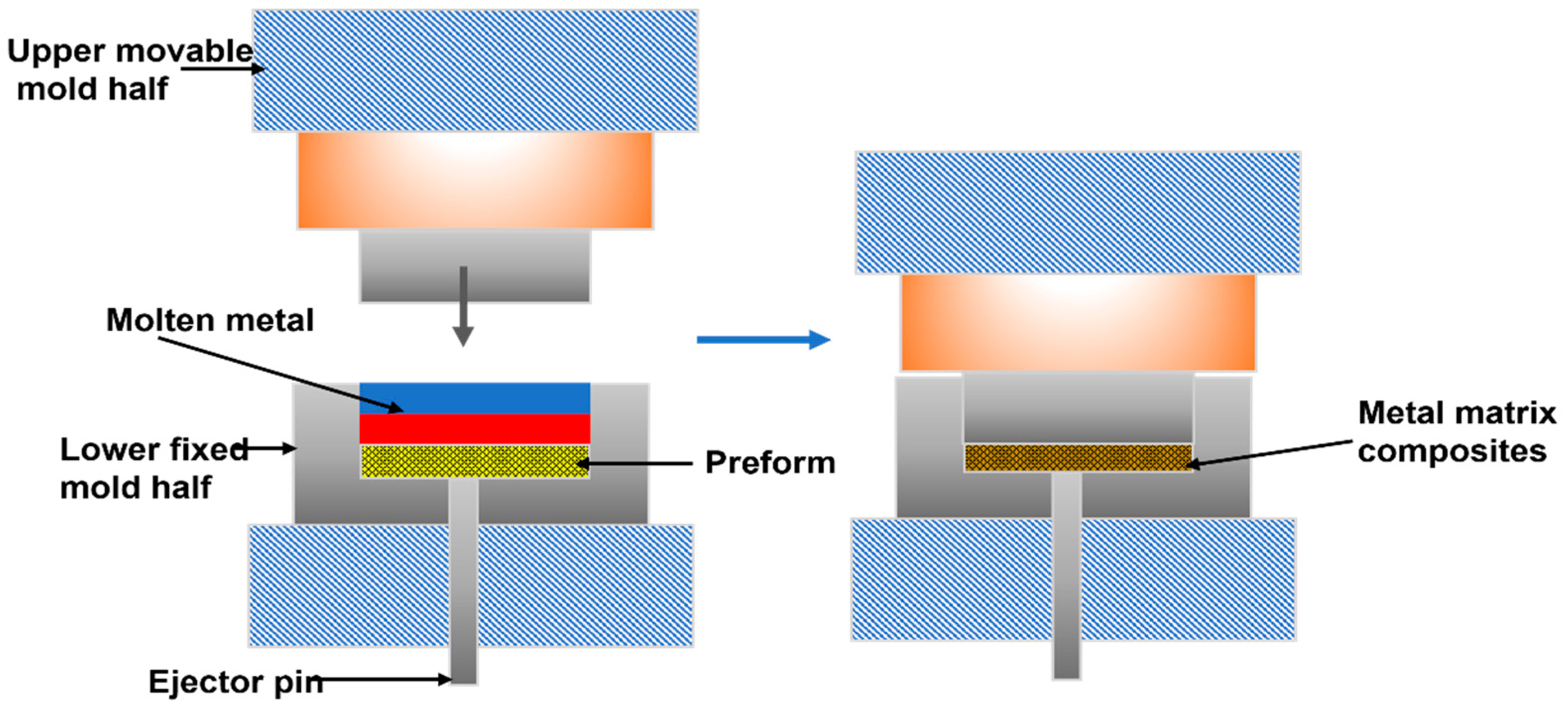
2.4.1. Liquid State Processing
2.4.2. Solid-State Processing
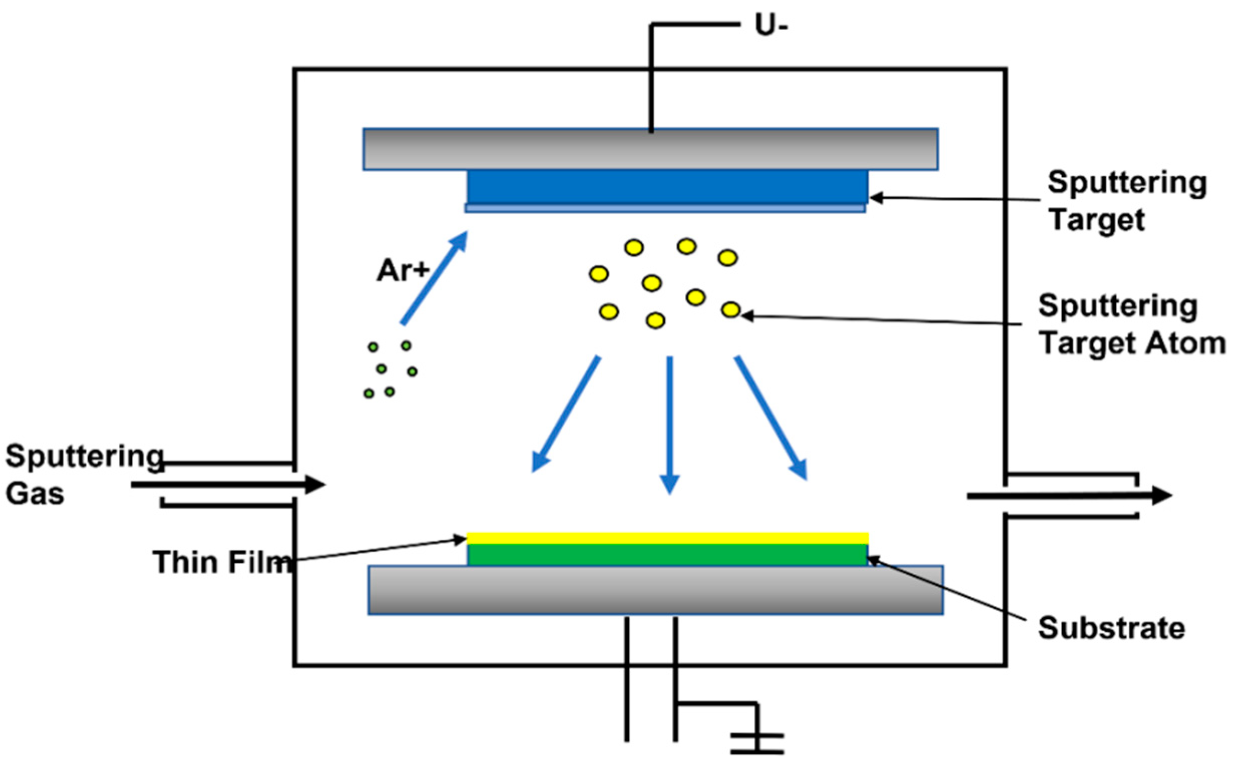
2.4.3. Vapor Deposition
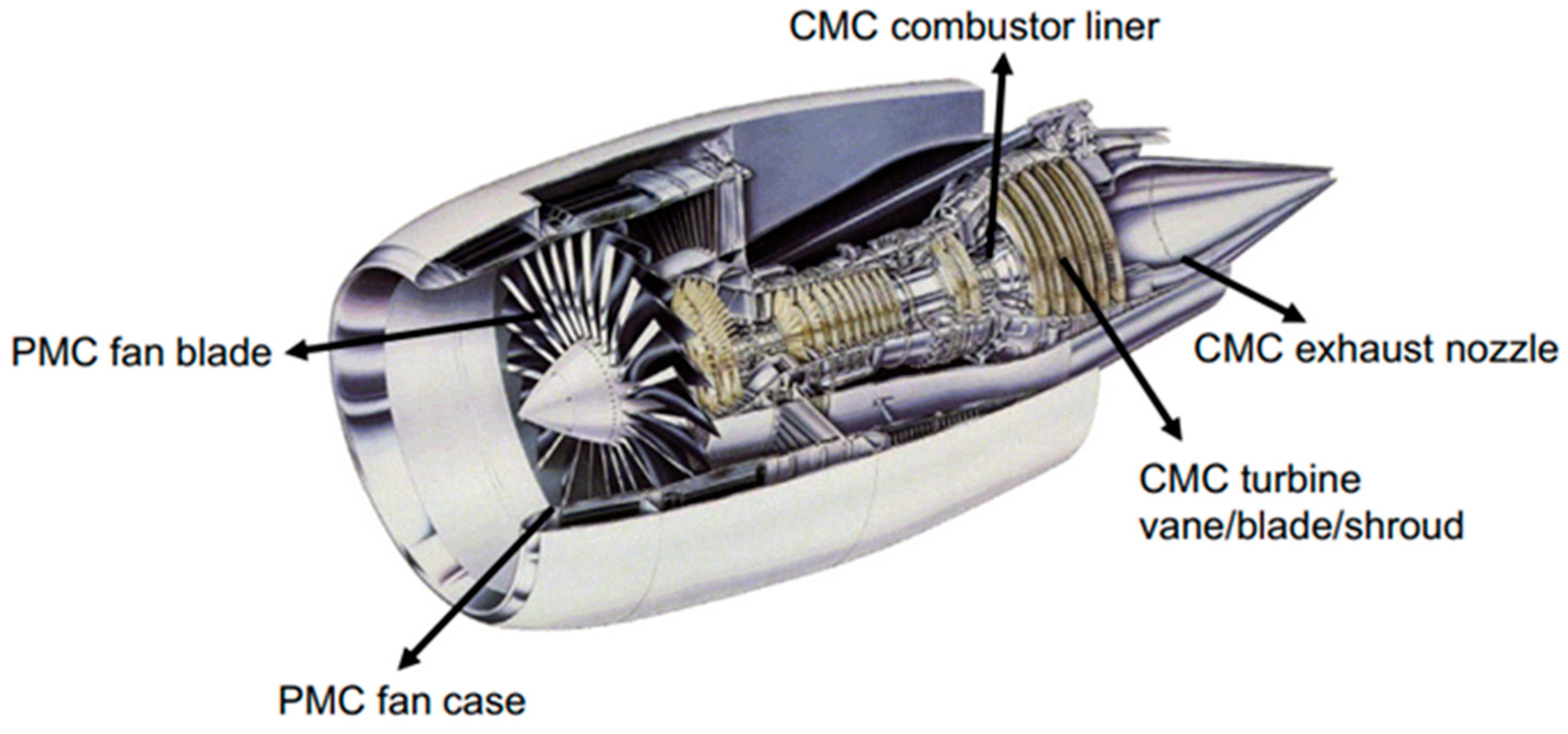
2.5. Applications of MMCs in Aircraft Components
3. Ceramics Matrix Composites
3.1. Manufacturing of CMCs
3.1.1. Reaction Sintering Process
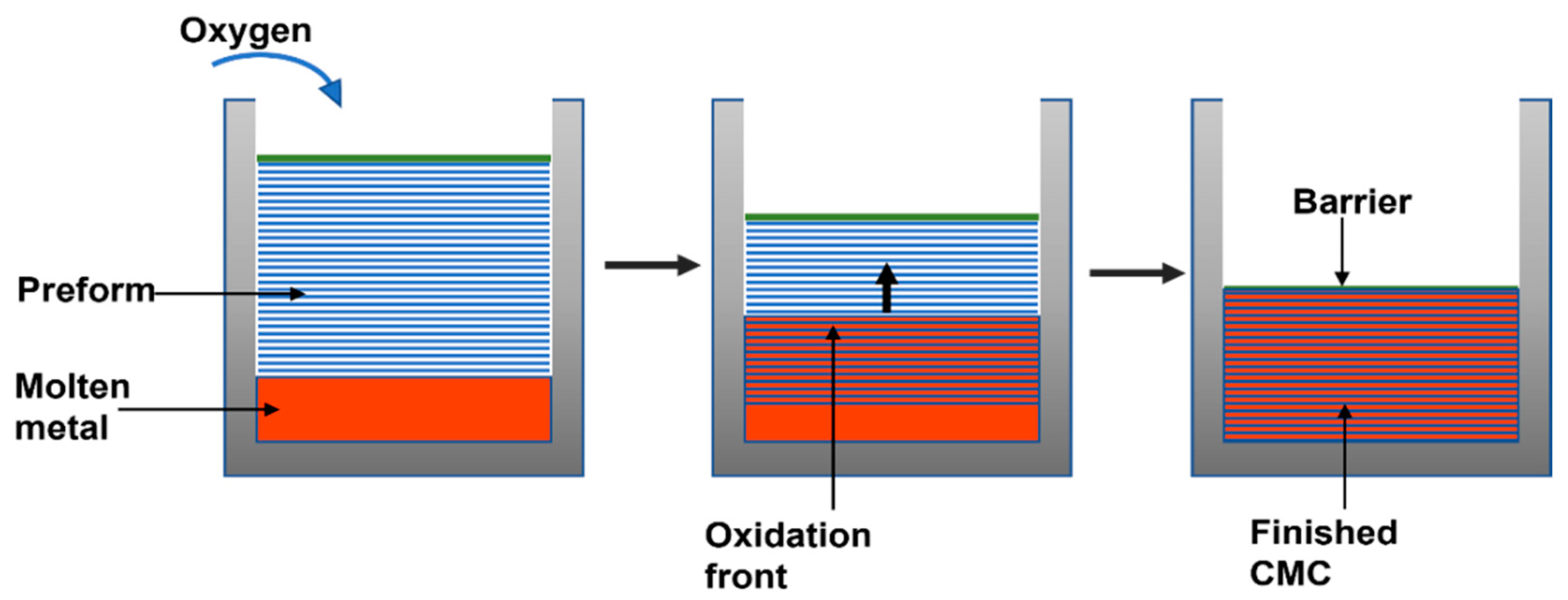
3.1.2. Liquid Infiltration Method
3.1.3. Sol-Gel Process
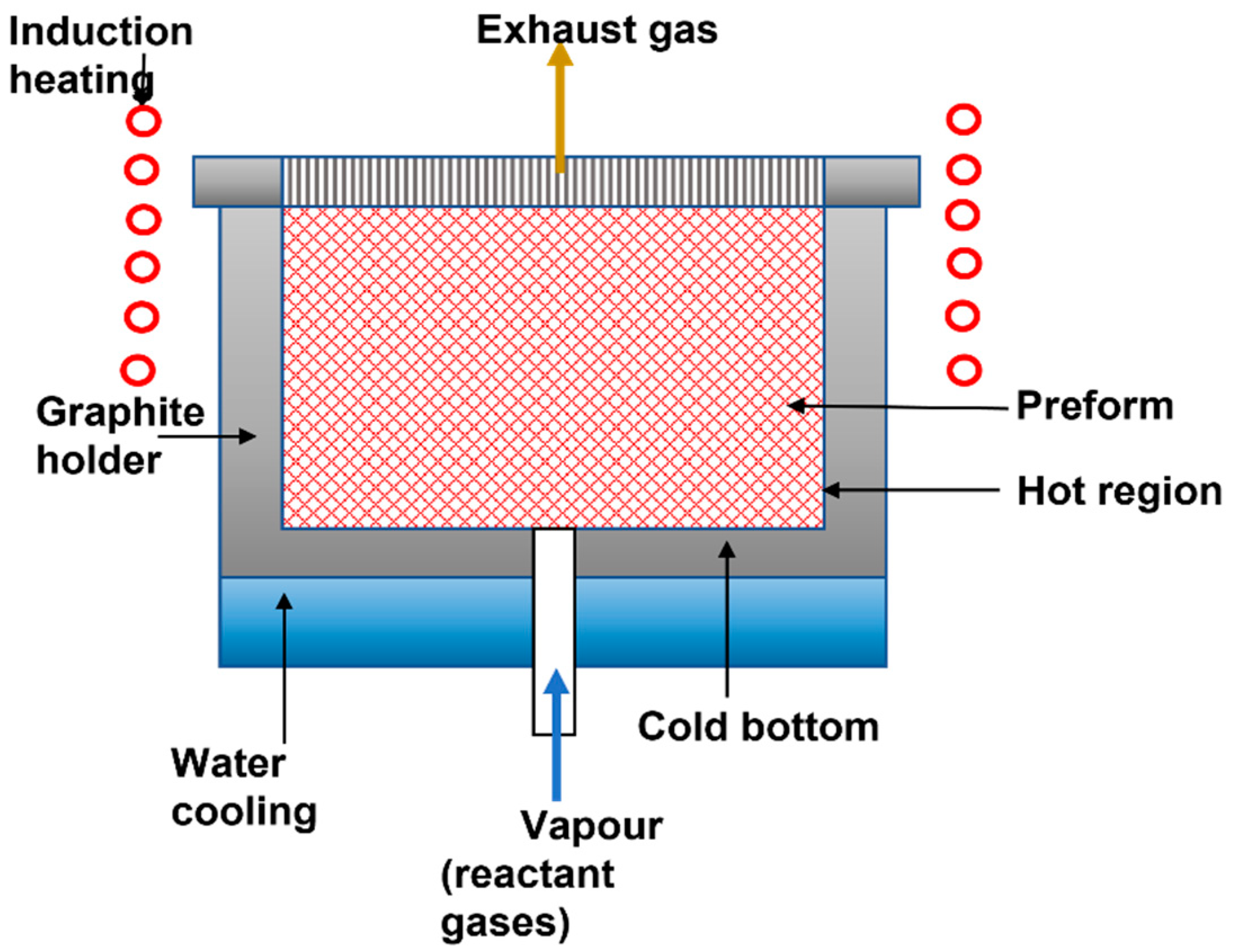
3.1.4. Chemical Vapor Infiltration (CVI)
3.2. Applications of CMCs in Aircraft Components
3.2.1. Turbine Blades
3.2.2. Braking System
3.2.3. Blisks (Blade Discs)
3.2.4. Exhaust Nozzle
3.2.5. Turbine Nozzle Blades
4. Polymer Matrix Composites
4.1. Manufacturing of PMCs
4.1.1. Injection Molding
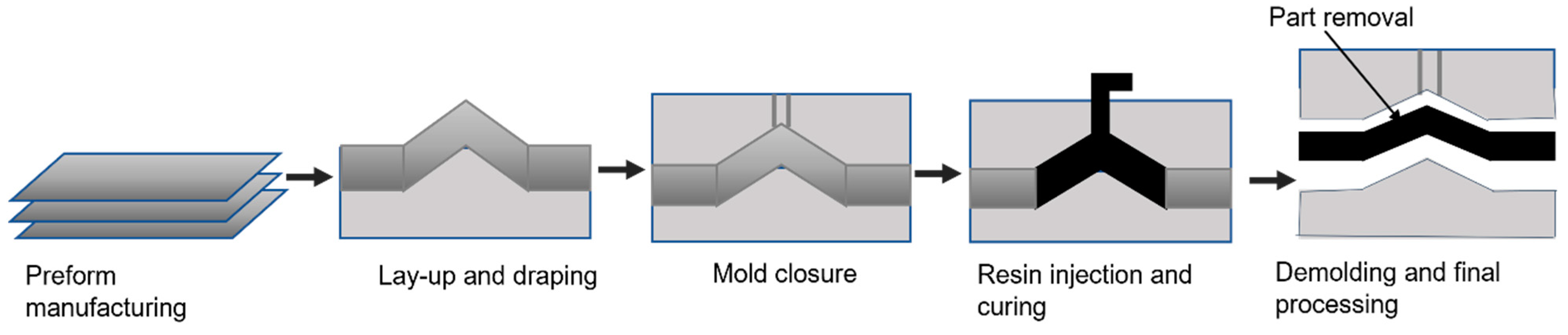
4.1.2. Resin Transfer Molding (RTM)
4.1.3. Compression Molding
4.1.4. Laying Prepreg
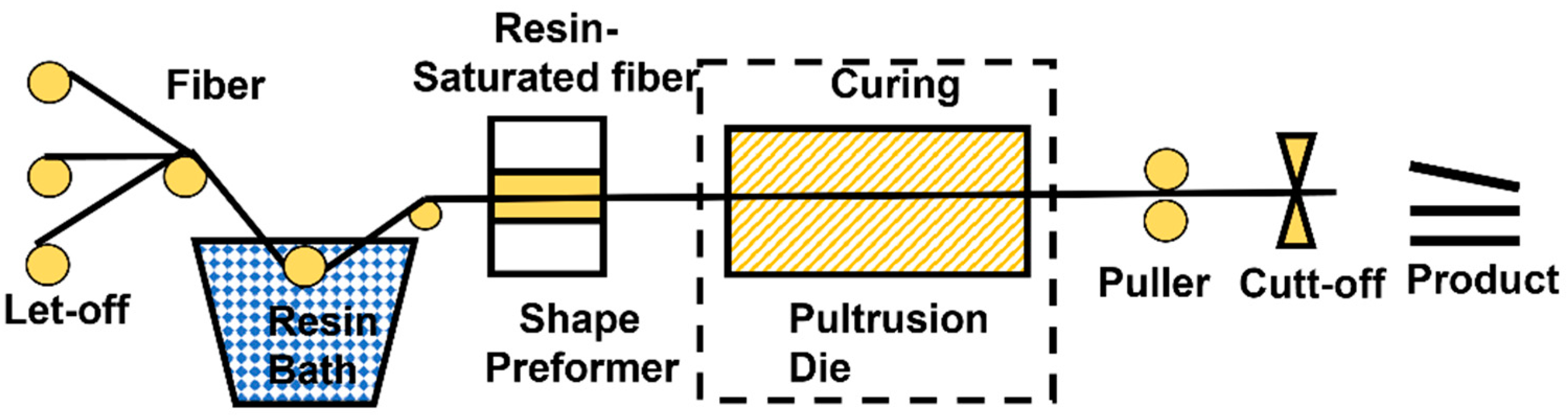
4.1.5. Pultrusion
4.2. Applications of PMCs in Aircraft Components
| Matrix | Reinforcements | Properties | Applications | Ref |
|---|---|---|---|---|
| Polymer | Hybrid kenaf/glass fiber | -High specific strength -Rain erosion resistance | -Aircraft brakes | [157] |
| Polypropylene | Hybrid bamboo/glass fiber | -Improved tensile strength -Increased fatigue life | -Aircraft structures | [158] |
| Polymer | Ramie fiber | -Reduction in weight (12–14%) | -Aircraft wing boxes | [159] |
| Polymer | Carbon fiber | -Design flexibility -High stiffness -Reduced scrap -Resistance to flames and heat -Fatigue resistance -Corrosion resistance -High strength -Damage and impact tolerance -Vibration-damping properties -Fracture resistance | -Aircraft brakes -Fuselage -Window frames -Aircraft wing -Rotors -Brackets -Boxes -Bulkheads -Fittings -Airframe -Blades -Vertical fins -Tail assemblies -Food tray arms | [160] |
| Polylactic acid (PLA) | Glass fiber | -Improved flexural properties -Improved tensile properties | -Engine access door -Acoustic liners -Vanes | [161] |
| Epoxy resin | Fiber | -Flame retardant -Good mechanical performance -Resistance to irradiation | -Aircraft structures | [162] |
| Epoxy resin | Carbon black | -Improved mechanical strength -Resistant to oxidation -Flame retardant | -Controlling static electricity in the avionics system | [163] |
| Epoxy resin | Epoxy resin Carbon fiber/S2-Glass fiber | -High OHT (open hole tension) strength -High deformation before fracture | -Aircraft structural framework | [164] |
| Silicone | Nano-carbon (graphene, carbon nanotube, and carbon black) | -Excellent performance at different temperature ranges -Resistant to chemicals, and aging, -Unique electrical insulation properties -Excellent resistance to oxidation | -Aircraft structure | [165] |
| Polymer | Carbon fiber | -Toughness -Durability | -Lockheed Martin F-35 (lighter fighter aircraft wings, horizontal fuselage, vertical and horizontal stabilizers) | [166] |
| Thermoset and thermoplastic resins | Carbon fabrics, glass fabrics, and Kevlar fabrics | -Lightweight -Negative refractive index -Negative permittivity, and permeability | -Radar-absorbing structures (stealth aircraft) | [167] |
4.3. Filler Dispersion Methods in Polymer Composite Processing
- Solution processing
- In situ polymerization
- Melt-mixing
4.3.1. Solution Processing
4.3.2. In Situ Polymerization
4.3.3. Melt-Mixing
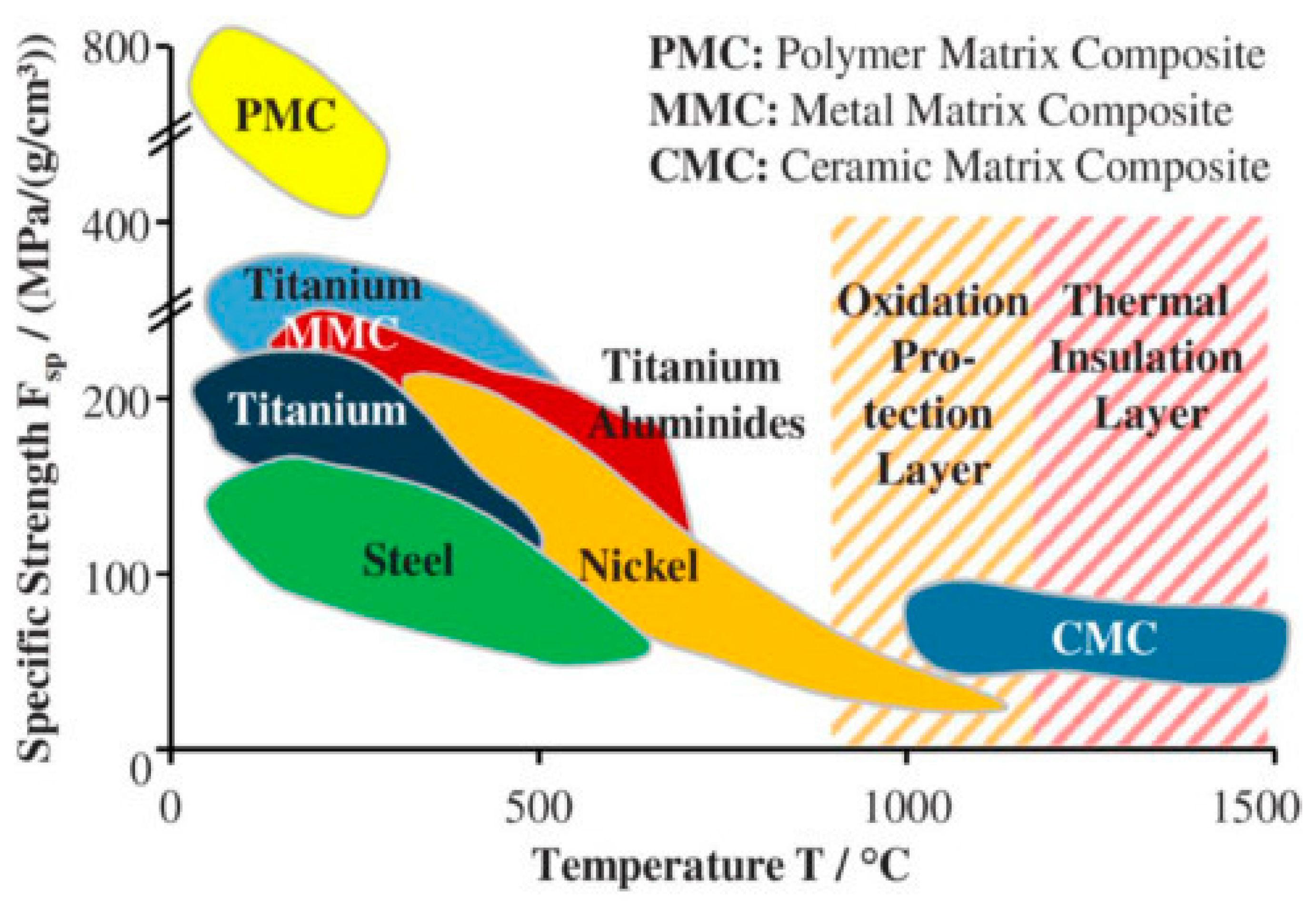
5. Properties of PMCs, MMCs, and CMCs Required for Aircraft Applications
6. Advanced Composites for Aircraft
6.1. Self-Healing Composites
6.2. Conductive Composites
6.3. Resin-Infused Composites
6.4. Nanocomposites
7. Challenges and the Future Perspective
8. Summary
Author Contributions
Funding
Institutional Review Board Statement
Informed Consent Statement
Data Availability Statement
Acknowledgments
Conflicts of Interest
References
- Dursun, T.; Soutis, C. Recent developments in advanced aircraft aluminium alloys. Mater. Des. 2014, 56, 862–871. [Google Scholar] [CrossRef]
- Vosteen, L.; Hadcock, R. Composite Chronicles: A Study of the Lessons Learned in the Development, Production, and Service of Composite Structures; NASA Contractor Report; NASA: Washington, DC, USA, 1994; 62p.
- Sullivan, R.; Rais-Rohani, M.; Lacy, T.; Alday, N. Structural testing of an ultralight UAV composite wing. In Proceedings of the 47th AIAA/ASME/ASCE/AHS/ASC Structures, Structural Dynamics, and Materials Conference 14th AIAA/ASME/AHS Adaptive Structures Conference 7th, Newport, RI, USA, 1–4 May 2006; pp. 3403–3412. [Google Scholar] [CrossRef]
- Aabid, A.; Parveez, B.; Parveen, N.; Khan, S.A.; Zayan, J.M.; Shabbir, O. Reviews on Design and Development of Unmanned Aerial Vehicle (Drone) for Different Applications. J. Mech. Eng. Res. Dev. 2022, 45, 53–69. [Google Scholar]
- Starke, E.A.; Staley, J.T. Application of modern aluminium alloys to aircraft, Fundam. Alum. Metall. Prod. Process. Appl. 2010, 32, 747–783. [Google Scholar] [CrossRef]
- Pantelakis, S.G.; Chamos, A.N.; Kermanidis, A.T. A critical consideration for the use of Al-cladding for protecting aircraft aluminum alloy 2024 against corrosion. Theor. Appl. Fract. Mech. 2012, 57, 36–42. [Google Scholar] [CrossRef]
- Kim, S.T.; Tadjiev, D.; Yang, H.T. Fatigue life prediction under random loading conditions in 7475-T7351 aluminum alloy using the RMS model. Int. J. Damage Mech. 2006, 15, 89–102. [Google Scholar] [CrossRef] [Green Version]
- Yu, J.; Li, X. Modelling of the precipitated phases and properties of Al-Zn-Mg-Cu alloys. J. Phase Equilibria Diffus. 2011, 32, 350–360. [Google Scholar] [CrossRef]
- Wanhill, R.J.H. Aerospace Applications of Aluminum-Lithium Alloys; Elsevier: Amsterdam, The Netherlands, 2013. [Google Scholar] [CrossRef]
- Composites, M.; Lakshmikanthan, A.; Angadi, S.; Malik, V.; Saxena, K.K.; Prakash, C.; Dixit, S.; Mohammed, K.A. Mechanical and Tribological Properties of Aluminum-Based Metal-Matrix Composites. Materials 2022, 15, 6111. [Google Scholar]
- Garg, P.; Jamwal, A.; Kumar, D.; Sadasivuni, K.K.; Hussain, C.M.; Gupta, P. Advance research progresses in aluminium matrix composites: Manufacturing & applications. J. Mater. Res. Technol. 2019, 8, 4924–4939. [Google Scholar] [CrossRef]
- Das, S. Primary magnesium production costs for automotive applications. JOM 2008, 60, 63–69. [Google Scholar] [CrossRef]
- Chen, Y.; Xu, Z.; Smith, C.; Sankar, J. Recent advances on the development of magnesium alloys for biodegradable implants. ACTA Biomater. 2014, 10, 4561–4573. [Google Scholar] [CrossRef]
- Czerwinski, F. Controlling the ignition and flammability of magnesium for aerospace applications. Corros. Sci. 2014, 86, 1–16. [Google Scholar] [CrossRef]
- Ostrovsky, L.; Henn, Y. Present state and future of magnesium application in aerospace industry. In Proceedings of the International Conference “New Challenges in Aeronautics” ASTEC, Moscow, Russia, 19–22 August 2007; Volume 7, pp. 1–5. [Google Scholar]
- Inagaki, I.; Takechi, T.; Shirai, Y.; Ariyasu, N. Application and features of titanium for the aerospace industry. Nippon. Steel Sumitomo Met. Tech. Rep. 2014, 106, 22–27. [Google Scholar]
- Sayuti, M. Metal Matrix Composite Products by Vibration Casting Method. Ref. Modul. Mater. Sci. Mater. Eng. 2016, 1–29. [Google Scholar] [CrossRef]
- Sommers, A.; Wang, Q.; Han, X.; Joen, C.T.; Park, Y.; Jacobi, A. Ceramics and ceramic matrix composites for heat exchangers in advanced thermal systems—A review. Appl. Therm. Eng. 2010, 30, 1277–1291. [Google Scholar] [CrossRef]
- Rambabu, V.V.K.P.; Prasad, N.E.; Wanhill, R.J.H. Aerospace Materials and Material Technologies. Aerosp. Mater. 2017, 1, 586. [Google Scholar] [CrossRef]
- Balakrishnan, S.T.P.; John, M.J.; Oothen, L.P.; Sreekala, M.S. Natural Fibre Composites and their Applications in Aerospace Engineering. In Advanced Composite Materials for Aerospace Engineering; Woodhead Publishing: Sawston, UK, 2014; pp. 365–383. [Google Scholar]
- Rajak, D.K.; Pagar, D.D.; Menezes, P.L.; Linul, E. Fiber-reinforced polymer composites: Manufacturing, properties, and applications. Polymers 2019, 11, 1667. [Google Scholar] [CrossRef] [Green Version]
- Merati, A.; Eastaugh, G. Determination of fatigue related discontinuity state of 7000 series of aerospace aluminum alloys. Eng. Fail. Anal. 2007, 14, 673–685. [Google Scholar] [CrossRef]
- Giummarra, C.; Thomas, B.; Rioja, R.J. New aluminum lithium alloys for aerospace applications. In Proceedings of the Light Metals Technology Conference, Montreal, QC, Canada, 24–26 September 2007; Volume 27, pp. 2–3. [Google Scholar]
- Aluminium Matrix Composites Offers Landing Gear Weight Reductions. Available online: https://www.aero-mag.com/alvant-aluminium-matrix-composites-landing-gear-weight-reductions/ (accessed on 3 July 2021).
- Koli, D.K.; Agnihotri, G.; Purohit, R. Advanced Aluminium Matrix Composites: The Critical Need of Automotive and Aerospace Engineering Fields. Mater. Today Proc. 2015, 2, 3032–3041. [Google Scholar] [CrossRef]
- Bharath, V.; Nagaral, M.; Auradi, V. Preparation of 6061Al-Al2O3 metal matrix composite by stir casting and evaluation of mechanical properties. Int. J. Metall. Mater. Sci. Eng. 2012, 2, 22–31. [Google Scholar]
- Meena, K.L.; Manna, D.A.; Banwait, D.S.S.; Jaswanti, D. An Analysis of Mechanical Properties of the Developed Al/SiC-MMC’s. Am. J. Mech. Eng. 2013, 1, 14–19. [Google Scholar] [CrossRef] [Green Version]
- Rahman, J.F.; Yunus, M.; Yezdani, T.M.T. Charting of a Strategy for the Application of Aluminium Metal Matrix Composites for Different Engineering Service Requirements. Int. J. Mod. Eng. Res. 2012, 2, 1408–1413. [Google Scholar]
- Kar, C.; Surekha, B. Effect of red mud and TiC on friction and wear characteristics of Al 7075 metal matrix composites. Aust. J. Mech. Eng. 2019, 20, 14–23. [Google Scholar] [CrossRef]
- Cui, Y.; Wang, L.; Ren, J. Multi-functional SiC/Al composites for aerospace applications. Chin. J. Aeronaut. 2008, 21, 578–584. [Google Scholar] [CrossRef]
- Kumar, M.S. SiC Reinforcement in the Synthesis and Characterization of A356/AL2O3/Sic/Gr Reinforced Composite—Paving a Way for the Next Generation of Aircraft Applications. Silicon 2020, 13, 2737–2744. [Google Scholar] [CrossRef]
- Kurzynowski, T.; Pawlak, A.; Smolina, I. The potential of SLM technology for processing magnesium alloys in aerospace industry. Arch. Civ. Mech. Eng. 2020, 20, 23. [Google Scholar] [CrossRef] [Green Version]
- Kasprzak, W.; Czerwinski, F.; Niewczas, M.; Chen, D.L. Correlating Hardness Retention and Phase Transformations of Al and Mg Cast Alloys for Aerospace Applications. J. Mater. Eng. Perform. 2015, 24, 1365–1378. [Google Scholar] [CrossRef]
- Arruebarrena, G.; Hurtado, I.; Väinölä, J.; Cingi, C.; Dévényi, S.; Townsend, J.; Mahmood, S.; Wendt, A.; Weiss, K.; Ben-Dov, A. Development of investment-casting process of Mg-alloys for aerospace applications. Adv. Eng. Mater. 2007, 9, 751–756. [Google Scholar] [CrossRef]
- Dash, D.; Samanta, S.; Rai, R.N. Study on Fabrication of Magnesium based Metal Matrix Composites and its improvement in Mechanical and Tribological Properties—A Review. In IOP Conference Series: Materials Science and Engineering; IOP Publishing: Bristol, UK, 2018; Volume 377. [Google Scholar] [CrossRef]
- Viswanathan, R.; Sivashankar, N.; Chandrakumar, S.; Karthik, R. Improving corrosion resistance of magnesium alloy for aerospace applications. Int. J. Mech. Prod. Eng. Res. Dev. 2019, 9, 769–774. [Google Scholar] [CrossRef]
- Anbarasan, A.; Alvin, P.A.; Kannan, K.; Lokesh, M. Mechanical characterisation of magnesium matrix composite for aerospace application. Int. J. Res. Anal. Rev. 2020, 7, 724–729. [Google Scholar]
- Rashad, M.; Pan, F.; Guo, W.; Lin, H.; Asif, M.; Irfan, M. Effect of alumina and silicon carbide hybrid reinforcements on tensile, compressive and microhardness behavior of Mg-3Al-1Zn alloy. Mater. Charact. 2015, 106, 382–389. [Google Scholar] [CrossRef]
- Metcalfe, A.G. Interaction and Fracture of Titanium-Boron Composites. J. Compos. Mater. 2015, 1, 356–365. [Google Scholar] [CrossRef]
- Guo, S. Fiber size effects on mechanical behaviours of SiC fibres-reinforced Ti3AlC2 matrix composites. J. Eur. Ceram. Soc. 2017, 37, 5099–5104. [Google Scholar] [CrossRef]
- Wu, T.; Qiao, J.; Jiang, D. Preparation and properties of carbon fiber/titanium alloy composite for automobile. Lect. Notes Electr. Eng. 2016, 364, 289–295. [Google Scholar] [CrossRef]
- Morsi, K.; Patel, V.V. Processing and properties of titanium-titanium boride (TiBw) matrix composites—A review. J. Mater. Sci. 2007, 42, 2037–2047. [Google Scholar] [CrossRef]
- Sivakumar, S.R.G.; Ananthi, V. Production and mechanical properties of nano SiC particle reinforced Ti–6Al–4V matrix composite. Trans. Nonferrous Met. Soc. China 2017, 27, 82–90. [Google Scholar] [CrossRef]
- Dougherty, T.; Xu, Y.; Hanizan, A. Mechanical properties and microstructure of PM Ti-Si3N4 discontinuous fibre composite. In TMS 2016 145th Annual Meeting & Exhibition, Annual Meeting Supplemental Proceedings; Springer: Cham, Switzerland, 2016; pp. 721–728. [Google Scholar] [CrossRef]
- Geng, L.; Ni, D.R.; Zhang, J.; Zheng, Z.Z. Hybrid effect of TiBw and TiCp on tensile properties of in situ titanium matrix composites. J. Alloys Compd. 2008, 463, 488–492. [Google Scholar] [CrossRef]
- Munir, K.S.; Kingshott, P.; Wen, C. Carbon nanotube reinforced titanium metal matrix composites prepared by powder metallurgy—A review. Crit. Rev. Solid State Mater. Sci. 2015, 40, 38–55. [Google Scholar] [CrossRef]
- Huang, L.J.; Geng, L.; Peng, H.X. Microstructurally inhomogeneous composites: Is a homogeneous reinforcement distribution optimal? Prog. Mater. Sci. 2015, 71, 93–168. [Google Scholar] [CrossRef]
- Cui, S.; Cui, C.; Xie, J.; Liu, S.; Shi, J. Carbon fibers coated with graphene reinforced TiAl alloy composite with high strength and toughness. Sci. Rep. 2018, 8, 2364. [Google Scholar] [CrossRef] [Green Version]
- Liu, C.; Huang, L.J.; Geng, L.; Jiao, Y.; Tang, A. In Situ Synthesis of (TiC + Ti3SiC2 + Ti5Si3)/Ti6Al4V Composites with Tailored Two-scale Architecture. Adv. Eng. Mater. 2015, 17, 933–941. [Google Scholar] [CrossRef]
- Kim, I.Y.; Choi, B.J.; Kim, Y.J.; Lee, Y.Z. Friction and wear behavior of titanium matrix (TiB + TiC) composites. Wear 2011, 271, 1962–1965. [Google Scholar] [CrossRef]
- An, Q.; Huang, L.J.; Bao, Y.; Zhang, R.; Jiang, S.; Geng, L.; Xiao, M. Dry sliding wear characteristics of in-situ TiBw/Ti6Al4V composites with different network parameters. Tribol. Int. 2018, 121, 252–259. [Google Scholar] [CrossRef]
- Chaudhari, R.; Bauri, R. A novel functionally gradient Ti/TiB/TiC hybrid composite with wear resistant surface layer. J. Alloys Compd. 2018, 744, 438–444. [Google Scholar] [CrossRef]
- Zhu, K.; Xu, Y.J.; Jing, T.; Hou, H.L. Fracture behavior of a composite composed by Ti-aluminide multi-layered and continuous-SiCf-reinforced Ti-matrix. Rare Met. 2017, 36, 925–933. [Google Scholar] [CrossRef]
- Launey, M.E.; Ritchie, R.O. On the fracture toughness of advanced materials. Adv. Mater. 2009, 21, 2103–2110. [Google Scholar] [CrossRef]
- Yan-Qing, Y.; Xian, L.; Bin, H.; Jian-kang, L.; Yan, C. Fracture toughness of SiCf/Ti-6Al-4V composites. Trans. Mater. Heat Treat. 2010, 31, 1–4. [Google Scholar]
- Hayat, M.D.; Singh, H.; He, Z.; Cao, P. Titanium metal matrix composites: An overview. Compos. Part A Appl. Sci. Manuf. 2019, 121, 418–438. [Google Scholar] [CrossRef]
- Takahashi, N.; Sato, T.; Nakatsuka, S.; Fujiwara, K.; Yoshida, K.; Yokozeki, T. Titanium Metal Matrix Composite development for commercial aircraft landing gear structure. In Proceedings of the 28th International Congress of the Aeronautical Sciences, Brisbane, QLD, Australia, 23–28 September 2012; Volume 3, pp. 1902–1909. [Google Scholar]
- Haghshenas, M. Metal—Matrix Composites. In Reference Module in Materials Science and Materials Engineering; Elsevier: Amsterdam, The Netherlands, 2016; pp. 1–28. [Google Scholar] [CrossRef]
- Yeshwanth, G.; Reddy, K.S. Static and dynamic analysis of aircraft wing made by LM 25 and ALSiC metal matrix composite. Int. J. Eng. Adv. Technol. 2019, 8, 1319–1325. [Google Scholar] [CrossRef]
- Diju, G.; Samuel, J.; Raja Dhas, G.E.; Ramanan, M. Ramachandran, Production and microstructure characterization of AA6061 matrix activated carbon particulate reinforced composite by friction stir casting method. Rasayan J. Chem. 2017, 10, 784–789. [Google Scholar] [CrossRef]
- Mavhungu, S.T.; Akinlabi, E.T.; Onitiri, M.A.; Varachia, F.M. Aluminium matrix composites for industrial use: Advances and trends. Procedia Manuf. 2017, 7, 178–182. [Google Scholar] [CrossRef]
- Sun, Y.; Choi, H.; Konishi, H.; Pikhovich, V.; Hathaway, R.; Chen, L.; Li, X. Effect of core-shelled nanoparticles of carbon-coated nickel on magnesium. Mater. Sci. Eng. A. 2012, 546, 284–290. [Google Scholar] [CrossRef]
- Shaga, A.; Shen, P.; Sun, C.; Jiang, Q. Lamellar-interpenetrated Al-Si-Mg/SiC composites fabricated by freeze casting and pressureless infiltration. Mater. Sci. Eng. A. 2015, 630, 78–84. [Google Scholar] [CrossRef]
- Dhanashekar, M.; Kumar, V.S.S. Squeeze casting of aluminium metal matrix composites—An overview. Procedia Eng. 2014, 97, 412–420. [Google Scholar] [CrossRef] [Green Version]
- Patil, J.; Patil, M.H. Squeeze Casting Fabrication Process Importance for MMC Fabrication—A Review. Int. J. Latest Technol. Eng. Manag. Appl. Sci. 2019, VIII, 44–47. [Google Scholar]
- Alhashmy, H. Fabrication of Aluminium Matrix Composites (AMCs) by Squeeze Casting Technique Using Carbon Fiber as Reinforcement. Ph.D. Thesis, University of Ottawa, Ottawa, ON, Canada, 2012. [Google Scholar]
- Singerman, S.A.; Jackson, J.J. Titanium Metal Matrix Composites for Aerospace Applications. In Superalloys 1996, Proceedings of eighth International Symposium on Superalloys, Champion, PA, USA, 22–26 September 1996; Minerals, Metals & Materials Society: Warrendale, PA, USA; pp. 579–586. [CrossRef]
- Chawla, N.; Chawla, K.K. Metal Matrix Composites; Springer: New York, NY, USA, 2013. [Google Scholar] [CrossRef] [Green Version]
- The Great Metal Tube in the Sky|Material Strategies. Available online: https://arch5541.wordpress.com/2013/01/08/the-great-metal-tube-in-the-sky/ (accessed on 6 July 2021).
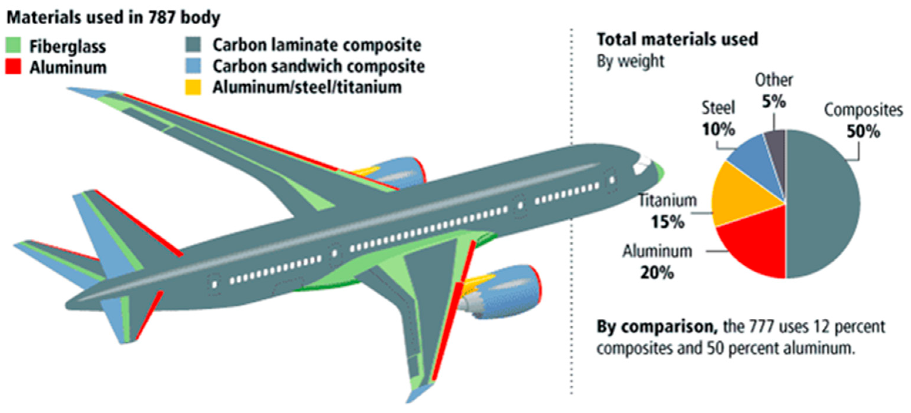
- Journal of Young Investigators. The Boeing 787 Dreamliner: Designing an Aircraft for the Future. 2020. Available online: https://www.jyi.org/2010-august/2010/8/6/the-boeing-787-dreamliner-designing-an-aircraft-for-the-future (accessed on 2 July 2021).
- Fahrenholtz, W.G.; Hilmas, G.E.; Talmy, I.G.; Zaykoski, J.A. Refractory diborides of zirconium and hafnium. J. Am. Ceram. Soc. 2007, 90, 1347–1364. [Google Scholar] [CrossRef]
- Silvestroni, L.; Sciti, D.; Melandri, C.; Guicciardi, S. Toughened ZrB2-based ceramics through SiC whisker or SiC chopped fiber additions. J. Eur. Ceram. Soc. 2010, 30, 2155–2164. [Google Scholar] [CrossRef]
- Halbig, M.C.; Jaskowiak, M.H.; Kiser, J.D.; Zhu, D. Evaluation of ceramic matrix composite technology for aircraft turbine engine applications. In Proceedings of the 51st AIAA Aerospace Sciences Meeting including the New Horizons Forum and Aerospace Exposition, Dallas, TX, USA, 7–10 January 2013. [Google Scholar] [CrossRef] [Green Version]
- Siskind, K.S.; Hartford, E.; Orlando, I.; Siskind, K.S. Glass-Ceramic Matrix Composites for Advanced Gas Turbines. In Proceedings of the 26th Joint Propulsion Conference, Orlando, FL, USA, 16–18 July 1990; p. 2014. [Google Scholar]
- Fan, S.; Zhang, L.; Cheng, L.; Tian, G.; Yang, S. Effect of braking pressure and braking speed on the tribological properties of C/SiC aircraft brake materials. Compos. Sci. Technol. 2010, 70, 959–965. [Google Scholar] [CrossRef]
- Fan, S.; Zhang, L.; Cheng, L.; Zhang, J.; Yang, S.; Liu, H. Wear mechanisms of the C/SiC brake materials. Tribol. Int. 2011, 44, 25–28. [Google Scholar] [CrossRef]
- Lu, Z.L.; Lu, F.; Cao, J.W.; Li, D.C. Manufacturing properties of turbine blades of carbon fiber-reinforced SiC composite based on stereolithography. Mater. Manuf. Process. 2014, 29, 201–209. [Google Scholar] [CrossRef]
- Fan, S.; Yang, C.; He, L.; Du, Y.; Krenkel, W.; Greil, P.; Travitzky, N. Progress of ceramic matrix composites brake materials for aircraft application. Rev. Adv. Mater. Sci. 2016, 44, 313–325. [Google Scholar]
- Low, I.M. Advances in ceramic matrix composites: Introduction. In Advances in Ceramic Matrix Composites, 2nd ed.; Woodhead Publishing: Sawston, UK, 2018; pp. 1–7. [Google Scholar] [CrossRef]
- Kumar, S.; Kumar, A.; Mala, R.B.; Mokhasunavisu, R.R. Fabrication and Ablation Studies of 4D C/SiC Composite Nozzle under Liquid Propulsion. Int. J. Appl. Ceram. Technol. 2015, 12, E176–E190. [Google Scholar] [CrossRef]
- Kumar, S.; Kumar, A.; Sampath, K.; Prasad, V.V.B.; Chaudhary, J.C.; Gupta, A.K.; Devi, G.R. Fabrication and erosion studies of C-SiC composite Jet Vanes in solid rocket motor exhaust. J. Eur. Ceram. Soc. 2011, 31, 2425–2431. [Google Scholar] [CrossRef]
- Lee, R.G.B.; Mitic, V. Proceedings of the IV Advanced Ceramics and Applications Conference; Atlantis Press: Paris, France, 2017. [Google Scholar]
- Vaidyaraman, S.; Purdy, M.; Walker, T.; Horst, S. C/SiC Material Evaluation for Aircraft Brake Applications. High Temp. Ceram. Matrix Compos. 2006, 802–808. [Google Scholar] [CrossRef]
- Lacombe, A.; Spriet, P.; Allaria, A.; Bouillon, E.; Habarou, G. Ceramic Matrix Composites to make breakthroughs in aircraft engine performance. In Proceedings of the 50th AIAA/ASME/ASCE/AHS/ASC Structures, Structural Dynamics, and Materials Conference 17th AIAA/ASME/AHS Adaptive Structures Conference 11th AIAA No, Palm Spring, CA, USA, 4–7 May 2009. [Google Scholar]
- Christin, F. Design, Fabrication and Applications of C/C, C/Si and SiC/SiC Composites. High Temp. Ceram. Matrix Compos. 2006, 729–743. [Google Scholar] [CrossRef]
- Awasthi, S.; Wood, J.L. Carbon/Carbon Composite Materials for Aircraft Brakes. In Ceramic Engineering and Science Proceedings, Proceedings of the 12th Annual Conference on Composites and Advanced Ceramic Materials; John Wiley & Sons, Inc.: Hoboken, NJ, USA, 2008; Volume 560, pp. 553–559. [Google Scholar] [CrossRef]
- Berdoyes, M. Snecma propulsion solide advanced technology SRM nozzles, history and future. In Proceedings of the 42nd AIAA/ASME/SAE/ASEE Joint Propulsion Conference & Exhibit, Sacramento, CA, USA, 9–12 July 2006; Volume 4, pp. 2888–2903. [Google Scholar] [CrossRef]
- Renz, R.; Krenkel, W. C/C-SiC Composites for High Performance Emergency Brake. In Proceedings of the 9th European Conference on Composite Materials, Design and Applications, Brighton, UK, 4–7 June 2000; Volume 2021, pp. 1–2. [Google Scholar]
- Schmidt, J.; Scheiffele, M.; Krenkel, W. Engineering of CMC Tubular Components. High Temp. Ceram. Matrix Compos. 2006, 826–831. [Google Scholar] [CrossRef]
- Labanti, M.; Martignani, G.; Mingazzini, C.; Minoccari, G.L.; Pilotti, L.; Ricci, A.; Weiss, R. Evaluation of Damage by Oxidation Corrosion at High Temperatures of Coated C/C-SiC Ceramic Composite. High Temp. Ceram. Matrix Compos. 2006, 218–223. [Google Scholar] [CrossRef]
- Chowdhury, P.; Sehitoglu, H.; Rateick, R. Damage tolerance of carbon-carbon composites in aerospace application. Carbon 2018, 126, 382–393. [Google Scholar] [CrossRef]
- How Do Aircraft Brakes Work?|Engineering 360. Available online: https://insights.globalspec.com/article/12903/how-do-aircraft-brakes-work (accessed on 2 July 2021).
- Krenkel, W. Carbon Fibre Reinforced Silicon Carbide Composites (C/SiC, C/C-SiC). In Handbook of Ceramic Composites; Springer: Boston, MA, USA, 2006; pp. 117–148. [Google Scholar] [CrossRef]
- Chen, M.; Qiu, H.; Jiao, J.; Wang, Y.; Xie, W. High temperature oxidation behavior of silicon carbide ceramic. Key Eng. Mater. 2016, 680, 89–92. [Google Scholar] [CrossRef]
- Udayakumar, A.; Ganesh, A.S.; Raja, S.; Balasubramanian, M. Effect of intermediate heat treatment on mechanical properties of SiCf/SiC composites with BN interphase prepared by ICVI. J. Eur. Ceram. Soc. 2011, 31, 1145–1153. [Google Scholar] [CrossRef]
- Yoshida, K. Development of silicon carbide fiber-reinforced silicon carbide matrix composites with high performance based on interfacial and microstructure control. J. Ceram. Soc. Jpn. 2010, 118, 82–90. [Google Scholar] [CrossRef] [Green Version]
- Ding, D.; Zhou, W.; Luo, F.; Chen, M.; Zhu, D. Mechanical properties and oxidation resistance of SiC f/CVI-SiC composites with PIP-SiC interphase. Ceram. Int. 2012, 38, 3929–3934. [Google Scholar] [CrossRef]
- Chen, M.; Qiu, H.; Xie, W.; Zhang, B.; Liu, S.; Luo, W.; Ma, X. Research Progress of Continuous Fiber Reinforced Ceramic Matrix Composite in Hot Section Components of Aero engine. In IOP Conference Series: Materials Science and Engineering; IOP Publishing: Bristol, UK, 2019; Volume 678. [Google Scholar] [CrossRef]
- Kiser, J.D.; David, K.E.; Davies, C.; Andrulonis, R.; Ashforth, C. Updating composite materials handbook-17 volume 5—ceramic matrix composites. Ceram. Trans. 2018, 263, 413–423. [Google Scholar] [CrossRef]
- The Ceramic Society of Japan. Advanced Ceramic Technologies & Products; Springer Science & Business Media: Tokyo, Japan, 2012; Volume 585, p. XV. [Google Scholar]
- Fangueiro, R. Advanced Composite Materials for Aerospace Engineering; Woodhead Publishing: Sawston, UK, 2016. [Google Scholar]
- Popov, O.; Vleugels, J.; Huseynov, A.; Vishnyakov, V. Reactive sintering of TiB2-SiC-CNT ceramics. Ceram. Int. 2019, 45, 22769–22774. [Google Scholar] [CrossRef]
- Levashov, E.A.; Mukasyan, A.S.; Rogachev, A.S.; Shtansky, D.V. Self-propagating high-temperature synthesis of advanced materials and coatings. Int. Mater. Rev. 2017, 62, 203–239. [Google Scholar] [CrossRef]
- Fujimura, T.; Cabe, J.L. HYPRSO-T Turbo Engine Research for HST Combined Cycle Engine; SAE Technical Paper; J-Global: Tokyo, Japan, 2019. [Google Scholar]
- Hypersonic Composites Resist Extreme Heat and Stress|NASA Spinoff. Available online: https://spinoff.nasa.gov/Spinoff2007/ip_5.html (accessed on 2 July 2021).
- Bansal, J.; Lamon, N.P. Ceramic Matrix Composites: Materials, Modeling and Technology; John Wiley & Sons: Hoboken, NJ, USA, 2014. [Google Scholar] [CrossRef]
- Misra, A. Composite Materials for Aerospace Propulsion Related to Air and Space Transportation; Woodhead Publishing: Sawston, UK, 2016. [Google Scholar] [CrossRef]
- James, N. (Ed.) Lightweight Composite Structures in Transport: Design, Manufacturing, Analysis and Performance; Woodhead Publishing: Sawston, UK, 2016. [Google Scholar]
- GE Passport Engine Debuts Ceramic Matrix Composite—Aerospace Manufacturing and Design. Available online: https://www.aerospacemanufacturinganddesign.com/article/ge-passport-engine-debuts-ceramic-matrix-composite-110613/ (accessed on 15 July 2021).
- Destefan, J. Ceramic Matrix Composites Make Inroads in Aerospace; Woodhead Publishing: Sawston, UK, 2013; Available online: https://ceramics.org/ceramic-tech-today/ceramic-matrix-composites-make-inroads-in-aerospace (accessed on 15 July 2021).
- Kameda, T.; Sayano, A.; Amiji, N.; Ichikawa, H.; Hamada, H.; Fujita, A.; Uozumi, T. Fabrication and mechanical properties of reaction sintered silicon carbide matrix composite. In Ceramic Engineering and Science Proceedings, Proceedings of the 21st Annual Conference on Composites, Advanced Ceramics, Materials, and Structures—A, Cocoa Beach, FL, USA, 12–16 January 1997; John Wiley & Sons, Inc.: Hoboken, NJ, USA, 2009; pp. 419–426. [Google Scholar]
- GE Successfully Tests World’s First Rotating Ceramic Matrix Composite Material for Next-Gen Combat Engine. Available online: https://www.geaviation.com/press-release/military-engines/ge-successfully-tests-worlds-first-rotating-ceramic-matrix-composite (accessed on 15 July 2021).
- Howard, C.E. Ceramic Matrix Composites in Aircraft Engines Projected to Double over Five Years, Stratview Research Predicts, SAE International. 2018. Available online: https://www.sae.org/news/2018/07/ceramic-matrix-composites-in-aircraft-engines-projected-to-double-over-five-years-stratview-research-predicts (accessed on 17 October 2022).
- Sharma, A.K.; Bhandari, R.; Sharma, C.; Dhakad, S.K.; Pinca-Bretotean, C. Polymer matrix composites: A state of art review. Mater. Today Proc. 2022, 57, 2330–2333. [Google Scholar] [CrossRef]
- Kesarwani, S. Polymer Composites in Aviation Sector. Int. J. Eng. Res. 2017, V6, 518–525. [Google Scholar] [CrossRef]
- Maria, M. Advanced composite materials of the future in aerospace industry. Incas Bull. 2013, 5, 139–150. [Google Scholar] [CrossRef]
- Atique, M.S.A.; Probha, N.N.; Nafi, A.S. Polymer composites: A blessing to modern aerospace engineering. In Proceedings of the International Conference on Mechanical, Industrial and Energy Engineering, Khulna, Bangladesh, 26–27 December 2014; pp. 1–6. [Google Scholar]
- Klocke, F.; Zeis, M.; Klink, A.; Veselovac, D. Experimental research on the Electrochemical Machining of modern titanium- and nickel-based alloys for aero engine components. Procedia CIRP 2013, 6, 368–372. [Google Scholar] [CrossRef] [Green Version]
- Dwi, A.Z.; Syamsudin, H. Manufacturing Fiberglass-Epoxy LSU-03 Aircraft Propeller Using Hand Lay-up and Vacuum Assisted Resin Transfer Moulding (VARTM) Methods. In IOP Conference Series: Materials Science and Engineering; IOP Publishing: Bristol, UK, 2019; Volume 645. [Google Scholar] [CrossRef]
- Asim, M.; Paridah, M.T.; Chandrasekar, M.; Shahroze, R.M.; Jawaid, M.; Nasir, M.; Siakeng, R. Thermal stability of natural fibers and their polymer composites. Iran. Polym. J. 2020, 29, 625–648. [Google Scholar] [CrossRef]
- Khajeh, A.; Mustapha, F.; Sultan, M.T.H.; Bánhegyi, G.; Karácsony, Z.; Baranyai, V. The Effect of Thermooxidative Aging on the Durability of Glass Fiber-Reinforced Epoxy. Adv. Mater. Sci. Eng. 2015, 2015, 372354. [Google Scholar] [CrossRef] [Green Version]
- Barile, C.; Casavola, C. Mechanical Characterization of Carbon Fiber-Reinforced Plastic Specimens for Aerospace Applications; Elsevier Ltd.: Amsterdam, The Netherlands, 2018. [Google Scholar] [CrossRef]
- Li, Y.; Wang, S.; Wang, Q. A molecular dynamics simulation study on enhancement of mechanical and tribological properties of polymer composites by introduction of graphene. Carbon 2017, 111, 538–545. [Google Scholar] [CrossRef]
- Guadagno, L.; Raimondo, M.; Vittoria, V.; Vertuccio, L.; Naddeo, C.; Russo, S.; de Vivo, B.; Lamberti, P.; Spinelli, G.; Tucci, V. Development of epoxy mixtures for application in aeronautics and aerospace. RSC Adv. 2014, 4, 15474–15488. [Google Scholar] [CrossRef]
- Oh, H.J.; Song, Y.S. Surface strengthening of injection molded parts by applying a thermal insulation film. RSC Adv. 2017, 7, 14302–14308. [Google Scholar] [CrossRef] [Green Version]
- Marcomini, A.L.; Rego, B.T.; Bretas, R.E.S. Improvement of the short- and long-term mechanical properties of injection-molded poly(etheretherketone) and hydroxyapatite nanocomposites. J. Appl. Polym. Sci. 2017, 134, 1–14. [Google Scholar] [CrossRef]
- Bledzki, A.K.; Faruk, O. Influence of different endothermic foaming agents on microcellular injection moulded wood fibre reinforced PP composites. Cell. Polym. 2006, 25, 143–158. [Google Scholar] [CrossRef]
- Wang, Y.H.; Chen, Y.K.; Rodrigue, D. Production of thermoplastic elastomers based on recycled pe and ground tire rubber: Morphology, mechanical properties and effect of compatibilizer addition. Int. Polym. Process. 2018, 33, 525–534. [Google Scholar] [CrossRef]
- Yang, B.; Fu, X.R.; Yang, W.; Liang, S.P.; Sun, N.; Hu, S.; Yang, M.B. Effect of melt and mold temperatures on the solidification behavior of HDPE during gas-assisted injection molding: An enthalpy transformation approach. Macromol. Mater. Eng. 2009, 294, 336–344. [Google Scholar] [CrossRef]
- Zheng, G.Q.; Yang, W.; Huang, L.; Li, Z.M.; Yang, M.B.; Yin, B.; Li, Q.; Liu, C.T.; Shen, C.Y. The role of gas penetration on morphological formation of polycarbonate/polyethylene blend molded by gas-assisted injection molding. J. Mater. Sci. 2007, 42, 7275–7285. [Google Scholar] [CrossRef]
- Demers, V.; Turenne, S.; Scalzo, O. Impact of binders on viscosity of low-pressure powder injection molded Inconel 718 superalloy. J. Mater. Sci. 2015, 50, 2893–2902. [Google Scholar] [CrossRef]
- Mohan, D.G.; Gopi, S.; Rajasekar, V.; Krishnan, K.; Mohan, D.G.; Selvarajan, L.; Rajavel, R.; Prakash, B.; Mohan, D.G.; Gopi, S.; et al. Microinjection moulded polyetheretherketone biomaterials as spinal implants: Physico-chemical and mechanical characterisation. Mater. Today Proc. 2019, 27, 1–31. [Google Scholar] [CrossRef] [Green Version]
- Leong, Y.W.; Thitithanasarn, S.; Yamada, K.; Hamada, H. Compression and Injection Molding Techniques for Natural Fiber Composites; Woodhead Publishing Limited: Sawaston, UK, 2013. [Google Scholar] [CrossRef]
- Dirckx, M.E.; Hardt, D.E. Analysis and characterization of demolding of hot embossed polymer microstructures. J. Micromechanics Microengineering 2011, 21, 085024. [Google Scholar] [CrossRef]
- Ye, H.; Liu, X.Y.; Hong, H. Fabrication of metal matrix composites by metal injection molding—A review. J. Mater. Process. Technol. 2008, 200, 12–24. [Google Scholar] [CrossRef] [Green Version]
- Hamidi, M.F.F.A.; Harun, W.S.W.; Samykano, M.; Ghani, S.A.C.; Ghazalli, Z.; Ahmad, F.; Sulong, A.B. A review of biocompatible metal injection moulding process parameters for biomedical applications. Mater. Sci. Eng. C 2017, 78, 1263–1276. [Google Scholar] [CrossRef] [Green Version]
- Fu, H.; Xu, H.; Liu, Y.; Yang, Z.; Kormakov, S.; Wu, D.; Sun, J. Overview of Injection Molding Technology for Processing Polymers and Their Composites. ES Mater. Manuf. 2020, 8, 3–23. [Google Scholar] [CrossRef]
- Arao, Y.; Yumitori, S.; Suzuki, H.; Tanaka, T.; Tanaka, K.; Katayama, T. Mechanical properties of injection-molded carbon fiber/polypropylene composites hybridized with nanofillers. Compos. Part A Appl. Sci. Manuf. 2013, 55, 19–26. [Google Scholar] [CrossRef]
- Li, J.; Yang, S.; Xu, F.; Jiang, S. Properties and Structure of Fiber-Reinforced Injection-Molded Part. In MATEC Web of Conferences, Proceedings of the International Symposium on Materials Application and Engineering (SMAE 2016), Chiang Mai, Thailand, 20–21 August 2016; EDP Sciences: Les Ulis, France, 2016; Volume 67, pp. 1–5. [Google Scholar] [CrossRef] [Green Version]
- Sozer, E.M.; Simacek, P.; Advani, S.G. Resin Transfer Molding (RTM) in Polymer Matrix Composites; Woodhead Publishing Limited: Sawston, UK, 2012. [Google Scholar] [CrossRef]
- Van Velthem, P.; Ballout, W.; Daoust, D.; Sclavons, M.; Cordenier, F.; Henry, E.; Dumont, D.; Destoop, V.; Pardoen, T.; Bailly, C. Influence of thermoplastic diffusion on morphology gradient and on delamination toughness of RTM-manufactured composites. Compos. Part A Appl. Sci. Manuf. 2015, 72, 175–183. [Google Scholar] [CrossRef]
- Laurenzi, S.; Marchetti, M. Advanced Composite Materials by Resin Transfer Molding for Aerospace Applications. In Composites and Their Properties; IntechOpen: London, UK, 2012. [Google Scholar] [CrossRef] [Green Version]
- Shuart, M.J.; Dexter, H.B.; Marchello, J.M.; Grenoble, R.W.; Dominion, O. Automated Fabrication Technologies for High Performance Polymer Composites; Technical Memorandum (TM); NASA: Washington, DC, USA, 1998.
- Park, C.H.; Lee, W.I. Compression Molding in Polymer Matrix Composites; Woodhead Publishing Limited: Saawston, UK, 2012. [Google Scholar] [CrossRef]
- Mitschang, P.; Hildebrandt, K. Polymer and composite moulding technologies for automotive applications. Adv. Mater. Automot. Eng. 2012, 210–229. [Google Scholar] [CrossRef]
- Eguémann, N.; Giger, L.; Roux, M.; Dransfeld, C.; Thiébaud, F.; Perreux, D. Compression moulding of complex parts for the aerospace with discontinuous novel and recycled thermoplastic composite materials. In Proceedings of the 19th International Conference on Composite Materials, Montréal, QC, Canada, 28 July–2 August 2013; pp. 6616–6626. [Google Scholar]
- Ramôa Correia, J. Pultrusion of advanced fibre-reinforced polymer (FRP) composites. In Advanced Fibre-Reinforced Polymer (FRP) Composites for Structural Applications; Woodhead Publishing: Sawston, UK, 2013; pp. 207–251. [Google Scholar] [CrossRef]
- Holmes, M. High volume composites for the automotive challenge. Reinf. Plast. 2017, 61, 294–298. [Google Scholar] [CrossRef]
- Elkington, M.; Bloom, D.; Ward, C.; Chatzimichali, A.; Potter, K. Hand layup: Understanding the manual process. Adv. Manuf. Polym. Compos. Sci. 2015, 1, 138–151. [Google Scholar] [CrossRef] [Green Version]
- Balakrishnan, S.; John, P.; Pothen, M.J.; Sreekala, L.; Thomas, M.S. Natural Lightweight Hybrid Composites for Aircraft Structural Applications; Woodhead Publishing: Sawaston, UK, 2016. [Google Scholar] [CrossRef]
- Acquah, C.; Datskov, I.; Mawardi, A.; Zhang, F.; Achenie, L.E.K.; Pitchumani, R.; Santos, E. Optimization under uncertainty of a composite fabrication process using a deterministic one-stage approach. Comput. Chem. Eng. 2006, 30, 947–960. [Google Scholar] [CrossRef]
- Joshi, S.C.; Chen, X. Time-variant simulation of multi-material thermal pultrusion. Appl. Compos. Mater. 2011, 18, 283–296. [Google Scholar] [CrossRef]
- Neelakante Gowda, G.R.; Varughese, B.; Arumugam, G. A 14-seater civil aircraft design with an innovative composite structure. JEC Compos. Mag. 2013, 6, 951–952. [Google Scholar]
- Viscardi, M.; Arena, M.; Cerreta, P.; Iaccarino, P. Design and prototyping of a novel composite architecture for a widebody landing gear bay. Mater. Today Proc. 2019, 34, 288–292. [Google Scholar] [CrossRef]
- Viscardi, M.; Arena, M.; Cerreta, P.; Iaccarino, P.; Imparato, S.I. Manufacturing and Validation of a Novel Composite Component for Aircraft Main Landing Gear Bay. J. Mater. Eng. Perform. 2019, 28, 3292–3300. [Google Scholar] [CrossRef]
- Arena, M.; Chiariello, A.; Castaldo, M.; di Palma, L. Vibration response aspects of a main landing gear composite door designed for high-speed rotorcraft. Aerospace 2021, 8, 52. [Google Scholar] [CrossRef]
- Arockiam, N.J.; Jawaid, M.; Saba, N. Sustainable Bio Composites for Aircraft Components; Elsevier Ltd.: Amsterdam, The Netherlands, 2018. [Google Scholar] [CrossRef]
- Raja, D.B.P.; Retnam, B.S.J. Effect of short fibre orientation on the mechanical characterization of a composite material-hybrid fibre reinforced polymer matrix. Bull. Mater. Sci. 2019, 42, 111. [Google Scholar] [CrossRef] [Green Version]
- Boegler, A.; Kling, O.; Empl, U.; Isikveren, D. Potential of Sustainable Materials in Wing Structural Design; Deutsche Gesellschaft für Luft-und Raumfahrt-Lilienthal-Oberth eV: Bonn, Germany, 2014; Volume 327, pp. 1–6. [Google Scholar]
- Irving, C.; Soutis, P.E. Polymer Composites in the Aerospace Industry; Woodhead Publishing: Sawston, UK, 2019. [Google Scholar]
- Yasa, E.; Ersoy, K. A review on the additive manufacturing of fiber reinforced polymer matrix composites, Solid Free. In Proceedings of the 2018 International Solid Freeform Fabrication Symposium, Austin, TX, USA, 13–15 August 2018; pp. 1024–1033. [Google Scholar]
- Toldy, A.; Szolnoki, B.; Marosi, G. Flame retardancy of fibre-reinforced epoxy resin composites for aerospace applications. Polym. Degrad. Stab. 2011, 96, 371–376. [Google Scholar] [CrossRef]
- Zhang, J.; Chevali, V.S.; Wang, H.; Wang, C.H. Current status of carbon fibre and carbon fibre composites recycling. Compos. Part B Eng. 2020, 193, 108053. [Google Scholar] [CrossRef]
- O’Higgins, R.M.; McCarthy, M.A.; McCarthy, C.T. Comparison of open hole tension characteristics of high strength glass and carbon fibre-reinforced composite materials. Compos. Sci. Technol. 2008, 68, 2770–2778. [Google Scholar] [CrossRef] [Green Version]
- Oladele, I.O.; Omotosho, T.F.; Adediran, A.A. Polymer-Based Composites: An Indispensable Material for Present and Future Applications. Int. J. Polym. Sci. 2020, 2020, 8834518. [Google Scholar] [CrossRef]
- Koniuszewska, A.G.; Kaczmar, J.W. Application of polymer based composite materials in transportation. Prog. Rubber Plast. Recycl. Technol. 2016, 32, 1–23. [Google Scholar] [CrossRef]
- Jayalakshmi, C.G.; Inamdar, A.; Anand, A.; Kandasubramanian, B. Polymer matrix composites as broadband radar absorbing structures for stealth aircrafts. J. Appl. Polym. Sci. 2019, 136, 47241. [Google Scholar] [CrossRef] [Green Version]
- Kumar, G.B.V.; Gouda, P.S.S.; Umarfarooq, M.A.; Polayya, C. Influence of MWCNTs on mechanical and viscoelastic properties of glass-carbon epoxy composite. AIP Conf. Proc. 2021, 2408, 020016. [Google Scholar] [CrossRef]
- Gouda, P.S.S.; Sridhar, I.; Umarfarooq, M.A. Crack suppression in glass epoxy hybrid L-bend composites through drawdown coating technique using nano and micro fillers. Mater. Today Proc. 2022, 62, 7292–7296. [Google Scholar] [CrossRef]
- Choukimath, M.C.; Banapurmath, N.R.; Riaz, F.; Patil, A.Y.; Jalawadi, A.R.; Mujtaba, M.A.; Shahapurkar, K.; Khan, T.M.Y.; Alsehli, M.; Soudagar, M.E.M.; et al. Experimental and Computational Study of Mechanical and Thermal Characteristics of h-BN and GNP Infused Polymer Composites for Elevated Temperature Applications. Materials 2022, 15, 5397. [Google Scholar] [CrossRef]
- Ojijo, V.; Ray, S.S. Processing Thermoset-Based Nanocomposites; Springer International Publishing: Cham, Switzerland, 2018. [Google Scholar] [CrossRef]
- Hallad, S.A.; Banapurmath, N.R.; Khan, T.M.Y.; Umarfarooq, M.A.; Soudagar, M.E.M.; Hunashyal, A.M.; Gujjar, S.V.; Yaradoddi, J.S.; Ganachari, S.S.; Elfasakhany, A.; et al. Statistical analysis of polymer nanocomposites for mechanical properties. Molecules 2021, 26, 4135. [Google Scholar] [CrossRef]
- Deshmukh, K.; Ahamed, M.B.; Deshmukh, R.R.; Pasha, S.K.K.; Bhagat, P.R.; Chidambaram, K. Biopolymer Composites with High Dielectric Performance: Interface Engineering; Elsevier Inc.: Amsterdam, The Netherlands, 2017. [Google Scholar] [CrossRef]
- Potts, J.R.; Dreyer, D.R.; Bielawski, C.W.; Ruoff, R.S. Graphene-based polymer nanocomposites. Polymers 2011, 52, 5–25. [Google Scholar] [CrossRef] [Green Version]
- Pötschke, P.; Mothes, F.; Krause, B.; Voit, B. Melt-mixed PP/MWCNT composites: Influence of CNT incorporation strategy and matrix viscosity on filler dispersion and electrical resistivity. Polymers 2019, 11, 189. [Google Scholar] [CrossRef] [Green Version]
- Gaska, K.; Manika, G.C.; Gkourmpis, T.; Tranchida, D.; Gitsas, A.; Kádár, R. Mechanical behavior of melt-mixed 3D hierarchical graphene/polypropylene nanocomposites. Polymers 2020, 12, 1309. [Google Scholar] [CrossRef]
- Klapiszewski, Ł.; Pawlak, F.; Tomaszewska, J.; Jesionowski, T. Preparation and characterization of novel pvc/silica-lignin composites. Polymers 2015, 7, 1767–1788. [Google Scholar] [CrossRef] [Green Version]
- Nguyen, T.T.; Nguyen, V.K.; Pham, T.T.H.; Pham, T.T.; Nguyen, T.D. Effects of surface modification with stearic acid on the dispersion of some inorganic fillers in pe matrix. J. Compos. Sci. 2021, 5, 270. [Google Scholar] [CrossRef]
- Pras, M.; Gérard, J.F.; Golanski, L.; Quintard, G.; Duchet-Rumeau, J. Key role of the dispersion of carbon nanotubes (Cnts) within epoxy networks on their ability to release. Polymers 2020, 12, 2530. [Google Scholar] [CrossRef] [PubMed]
- Yan, H.; Shirato, N.; Zhu, X.; Rosenmann, D.; Tong, X.; Xu, W.; Petrovic, C.; Rose, V.; Nazaretski, E. X-ray Assisted Scanning Tunneling Microscopy and its applications for materials science: The first results on Cu doped ZrTe3. Crystals 2019, 9, 588. [Google Scholar] [CrossRef]
- Boyer, R.R.; Cotton, J.D.; Mohaghegh, M.; Schafrik, R.E. Materials considerations for aerospace applications. MRS Bull. 2015, 40, 1055–1065. [Google Scholar] [CrossRef] [Green Version]
- Hannula, S.P.; Lintula, P.; Lintunen, P.; Lindroos, T. Processing and properties of metal matrix composites synthesized by SHS. Mater. Sci. Forum 2003, 426–432, 1971–1978. [Google Scholar] [CrossRef]
- May, M.; Rupakula, G.D.; Matura, P. Non-polymer-matrix composite materials for space applications. Compos. Part C Open Access 2020, 3, 100057. [Google Scholar] [CrossRef]
- Alam, P.; Mamalis, D.; Robert, C.; Floreani, C.; Brádaigh, C.M.Ó. The fatigue of carbon fibre reinforced plastics—A review. Compos. Part B Eng. 2019, 166, 555–579. [Google Scholar] [CrossRef] [Green Version]
- Andrianov, A.; Lee, J.; Possa, G.; de Silva, H. Experimental study of the insulating effectiveness of silicone rubber composites by oxyacetylene ablation testing. J. Aerosp. Technol. Manag. 2020, 12, 1–11. [Google Scholar] [CrossRef]
- Xu, Y.; van Hoa, S. Mechanical properties of carbon fiber reinforced epoxy/clay nanocomposites. Compos. Sci. Technol. 2008, 68, 854–861. [Google Scholar] [CrossRef]
- Mustapha, F.; Aris, K.D.M.; Wardi, N.A.; Sultan, M.T.H.; Shahrjerdi, A. structural health monitoring (SHM) for composit structure undergoing tensile and thermal testing. J. Vibroengineering 2012, 14, 1342–1353. [Google Scholar]
- Bekas, D.G.; Tsirka, K.; Baltzis, D.; Paipetis, A.S. Self-healing materials: A review of advances in materials, evaluation, characterization and monitoring techniques. Compos. Part B Eng. 2016, 87, 92–119. [Google Scholar] [CrossRef]
- Wu, X.F.; Rahman, A.; Zhou, Z.; Pelot, D.D.; Sinha-Ray, S.; Chen, B.; Payne, S.; Yarin, A.L. Electrospinning core-shell nanofibers for interfacial toughening and self-healing of carbon-fiber/epoxy composites. J. Appl. Polym. Sci. 2013, 129, 1383–1393. [Google Scholar] [CrossRef]
- Das, R.; Melchior, C.; Karumbaiah, K.M. Self-Healing Composites for Aerospace Applications; Elsevier Ltd.: Amsterdam, The Netherlands, 2016. [Google Scholar] [CrossRef]
- Williams, G.; Trask, R.; Bond, I. A self-healing carbon fibre reinforced polymer for aerospace applications. Compos. Part A Appl. Sci. Manuf. 2007, 38, 1525–1532. [Google Scholar] [CrossRef]
- Kim, I. Carbon-Carbon Composite Application Areas and Limitations Fasil. J. Ergon. 2016, 6, 17–19. [Google Scholar]
- Fu, Q.G.; Li, H.J.; Shi, X.H.; Li, K.Z.; Wei, J.; Huang, M. Oxidation protective glass coating for SiC coated carbon/carbon composites for application at 1773 K. Mater. Lett. 2006, 60, 431–434. [Google Scholar] [CrossRef]
- Zhu, Y.; Cao, K.; Chen, M.; Wu, L. Synthesis of UV-Responsive Self-Healing Microcapsules and Their Potential Application in Aerospace Coatings. ACS Appl. Mater. Interfaces 2019, 11, 33314–33322. [Google Scholar] [CrossRef]
- Gao, R.X.K.; Lee, H.M.; Yang, Z.; Thitsartarn, W.; Gao, S.P.; Liu, E.X. Lightning Direct Effect and Electromagnetic Shielding Analysis of Conductive Aircraft Composite. In Proceedings of the 2019 International Symposium on Electromagnetic Compatibility-EMC EUROPE, Barcelona, Spain, 2–6 September 2019; pp. 355–359. [Google Scholar] [CrossRef]
- Alemour, B.; Yaacob, M.H.; Lim, H.N.; Hassan, M.R. Review of electrical properties of graphene conductive composites. Int. J. Nanoelectron. Mater. 2018, 11, 371–398. [Google Scholar]
- Bedel, V.; Lonjon, A.; Dantras, É.; Bouquet, M. Innovative conductive polymer composite coating for aircrafts lightning strike protection. J. Appl. Polym. Sci. 2020, 137, 48700. [Google Scholar] [CrossRef]
- Yadav, R.; Tirumali, M.; Wang, X.; Naebe, M.; Kandasubramanian, B. Polymer composite for antistatic application in aerospace. Def. Technol. 2020, 16, 107–118. [Google Scholar] [CrossRef]
- Alemour, B.; Badran, O.; Hassan, M.R. A review of using conductive composite materials in solving lightening strike and ice accumulation problems in aviation. J. Aerosp. Technol. Manag. 2019, 11, 1–23. [Google Scholar] [CrossRef] [Green Version]
- Marx, J.C.; Robbins, S.J.; Grady, Z.A.; Palmieri, F.L.; Wohl, C.J.; Rabiei, A. Polymer infused composite metal foam as a potential aircraft leading edge material. Appl. Surf. Sci. 2020, 505, 144114. [Google Scholar] [CrossRef]
- Arena, M.; Viscardi, M.; Barra, G.; Vertuccio, L.; Guadagno, L. Multifunctional performance of a Nano-Modified fiber reinforced composite aeronautical panel. Materials 2019, 16, 869. [Google Scholar] [CrossRef] [PubMed] [Green Version]
- Vertuccio, L.; Guadagno, L.; Spinelli, G.; Lamberti, P.; Tucci, V.; Russo, S. Piezoresistive properties of resin reinforced with carbon nanotubes for health-monitoring of aircraft primary structures. Compos. Part B Eng. 2016, 107, 192–202. [Google Scholar] [CrossRef]
- Sun, Y.; Mei, J.; Hu, H.; Ying, J.; Zhou, W.; Zhao, X.; Peng, S. In-situ Polymerization of exfoliated structure PA6/organo-clay nanocomposites. Rev. Adv. Mater. Sci. 2020, 59, 434–440. [Google Scholar] [CrossRef]
- Kumar, M.; Kumar, R.; Kumar, S. Synergistic effect of carbon nanotubes and nano-hydroxyapatite on mechanical properties of polyetheretherketone based hybrid nanocomposites. Polym. Polym. Compos. 2021, 29, 1365–1376. [Google Scholar] [CrossRef]
- Wang, Z.; Xiao, H. Nanocomposites: Recent development and potential automotive applications. SAE Int. J. Mater. Manuf. 2009, 1, 631–640. [Google Scholar] [CrossRef]
- Sameezadeh, M.; Emamy, M.; Farhangi, H. Effects of particulate reinforcement and heat treatment on the hardness and wear properties of AA 2024-MoSi2 nanocomposites. Mater. Des. 2011, 32, 2157–2164. [Google Scholar] [CrossRef]
- Hu, Z.; Tong, G.; Nian, Q.; Xu, R.; Saei, M.; Chen, F.; Chen, C.; Zhang, M.; Guo, H.; Xu, J. Laser sintered single layer graphene oxide reinforced titanium matrix nanocomposites. Compos. Part B Eng. 2016, 93, 352–359. [Google Scholar] [CrossRef]
- Guo, Y.; Zou, D.; Zhu, W.; Yang, X.; Zhao, P.; Chen, C.; Shuai, M. Infrared induced repeatable self-healing and removability of mechanically enhanced graphene-epoxy flexible materials. RSC Adv. 2019, 9, 14024–14032. [Google Scholar] [CrossRef] [Green Version]
- Zhao, W.; Li, M.; Peng, H.X. Functionalized MWNT-doped thermoplastic polyurethane nanocomposites for aerospace coating applications. Macromol. Mater. Eng. 2010, 295, 838–845. [Google Scholar] [CrossRef]
- Meenakshi, K.S.; Sudhan, E.P.J.; Kumar, S.A.; Umapathy, M.J. Development and characterization of novel DOPO based phosphorus tetraglycidyl epoxy nanocomposites for aerospace applications. Prog. Org. Coat. 2011, 72, 402–409. [Google Scholar] [CrossRef]
- García, C.; Fittipaldi, M.; Grace, L.R. Epoxy/montmorillonite nanocomposites for improving aircraft radome longevity. J. Appl. Polym. Sci. 2015, 132, 1–9. [Google Scholar] [CrossRef]
- Divagar, S.; Vigneshwar, M.; Selvamani, S.T. Impacts of Nano Particles on Fatigue Strength of Aluminum Based Metal Matrix Composites for Aerospace. Mater. Today Proc. 2016, 3, 3734–3739. [Google Scholar] [CrossRef]
- Yang, W.; Wang, L.; Song, B. Dove: A biomimetic flapping-wing micro air vehicle. Int. J. Micro Air Veh. 2018, 10, 70–84. [Google Scholar] [CrossRef]
- Bhat, A.; Budholiya, S.; Raj, S.A.; Sultan, M.T.H.; Hui, D.; Shah, A.U.M.; Safri, S.N.A. Review on nanocomposites based on aerospace applications. Nanotechnol. Rev. 2021, 10, 237–253. [Google Scholar] [CrossRef]


| Composites | Matrix | Reinforcement | Properties | Application | Ref. |
|---|---|---|---|---|---|
| ZrB2 or HfB2/SiC or Al2O3 | ZrB2 or HfB2 | SiC or Al2O3 | -High oxidation resistance (2000 °C and above) | -Hypersonic flight (rocket propulsion and atmospheric re-entry) | [72] |
| ZrB2/SiC (Whisker or chopped fiber) | ZrB2 | SiC chopped fiber or SiC whisker | -Good fracture toughness -High room-temperature strength -High-temperature strength | -High-temperature components | [73] |
| Oxide/oxide | Oxide | Oxide | -High performance -Reduced noise -Durability -Weight reduction | -Subsonic jet engines (exhaust mixer nozzle) | [74] |
| Glass-ceramic | Ceramic | Glass | -Lightweight -High temperature -Lightweight -Better performance -Reduced thrust-specific fuel consumption | -Aircraft compressor, combustor, and turbine | [75] |
| C/SiC | SiC | Carbon fiber | -Better tribological properties | -Aircraft brakes | [76,77] |
| C/SiC | SiC | Carbon fiber | -Bending strength -Fracture toughness | -Turbine blades | [78] |
| C/SiC | SiC | Carbon fiber | -Withstand temperatures up to 1200 °C | -Aircraft brakes | [79] |
| SiC | SiC | Carbon fiber | -Weight reduction -Improved retardation -Wear resistance -Improved carrier load and availability -Reduction in maintenance cost | -Aircraft brake (disks and rotors) | [80] |
| C/SiC | SiC | Carbon fiber | -Good thermo-erosive properties (up to 2000 °C) -High oxidation resistance -High strength-to-weight ratio | -Structural re-entry components -High-performance heat shields -Brake discs -Rocket nozzles -High-temperature heat exchanger tubes | [81] |
| C–SiC | SiC | Carbon fiber | -Average linear and mass erosion rate -Excellent resistance to thermo-oxidative erosion -Erosion resistance -High thermal conductivity -Good strength -Low CTE -Excellent thermal shock resistance | -Jet vanes | [82] |
| C/SiC | SiC | Carbon fiber | -Lightweight -Low density -High and stable coefficient of friction -High wear resistance | -Aircraft brake systems (brake pads and disks) | [83] |
| C/SiC | SiC | Carbon fiber | -Good thermal and mechanical properties -Higher Friction coefficients | -Aircraft brakes | [84] |
| SiC/SiC (CERASEPâA373) | SiC | Carbon fiber | -High fracture strength | -Engine combustor (rig and inner and outer liners) | [85] |
| SiC/C (SEPCARBINOXA262) | SiC | -Good specific strength | -Outer flaps (Rafale Fighter M88 engine A262) | [85] | |
| SiC/Carbon fiber (C) | SiC | -Weight reduction (50%) as compared to superalloy flap (Inconel 718) | SNECMA M 88-2 engine (Flame-holders, engine flaps, and exhaust cones) | [86] |
| Composites | Properties | Application | Reference |
|---|---|---|---|
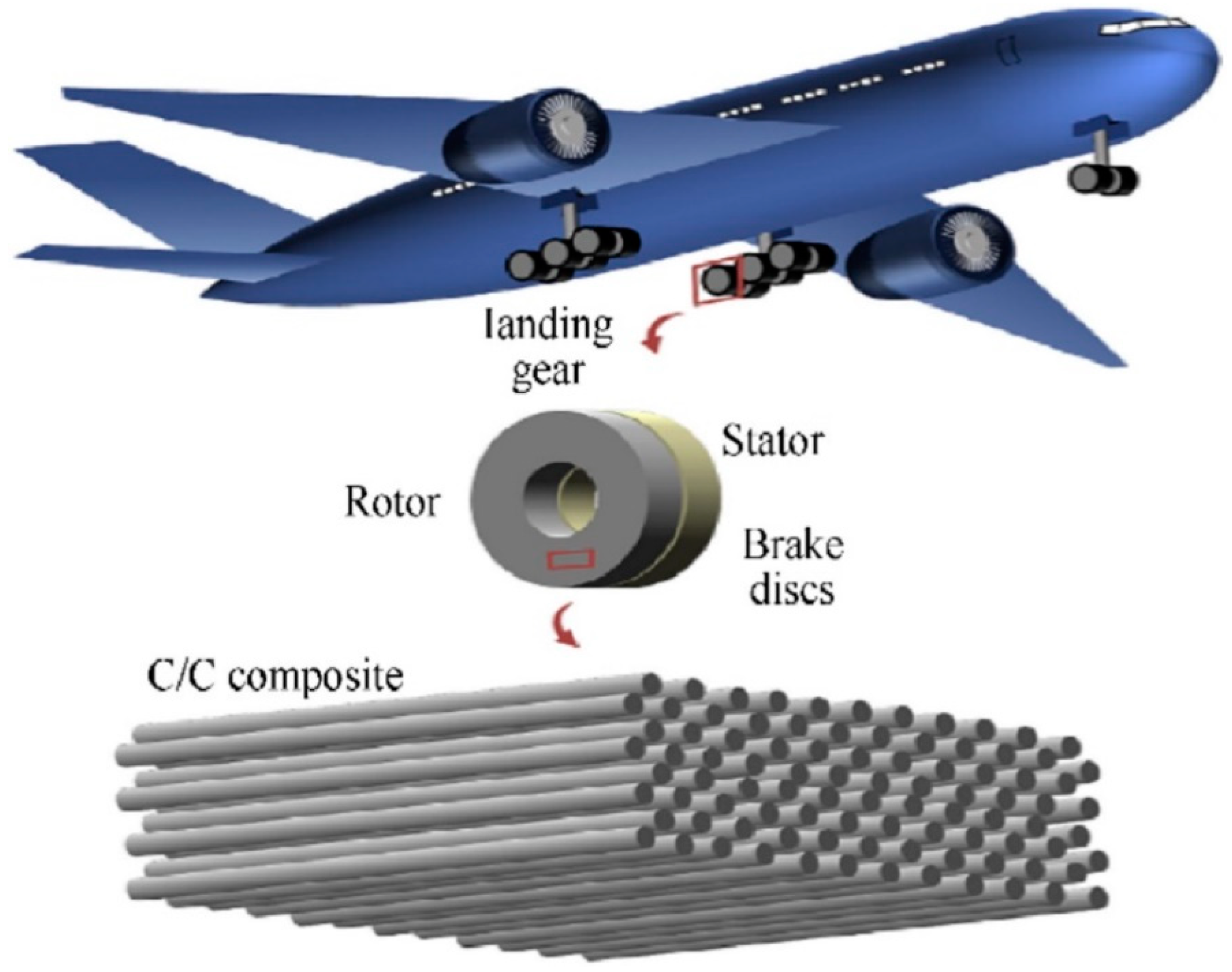
| Carbon/Carbon composites | -Lightweight (40%) -Good thermal shock resistance -Good tribological properties -High heat capacity (2.5 steel) -High strength (2 steel) | Boeing 767–300 -Aircraft brakes (brake disc) | [87] |
| Carbon/Carbon composites | -Lightweight as compared to phenolic nozzle | Rocket nozzles (throat and exit cones) | [88] |
| C/C-SiC (SiC infiltrated C/C composites) | -Smaller size brake systems -High coefficients of friction -Higher transmitted braking power -Low wear rates (at temperatures above 1000 °C) | -Emergency brake systems | [89] |
| C/C-SiC (SiC infiltrated C/C composites) | -Microporous -High thermal shock resistance -Corrosion resistance -Good sealing agent for the pressurized pipes -Oxidation resistance at high temperatures | -Coated pipes | [90,91] |
| Composite | PMCs | MMCs | CMCs |
|---|---|---|---|
| Microstructure | Long chain of molecules (fiber and matrices) | Predominantly metallic bond with a crystalline structure | Predominantly amorphous or crystalline structure |
| Mechanical | These are one of the lightest of the three composite materials and are found to have high specific strength and modulus. PMCs are brittle in nature. | These composites are ductile and have relatively high strength as well as high modulus compared to CMCs but are relatively heavier compared to PMCs. | These composites have very high strength and modulus compared to both PMCs and MMCs but are very brittle in nature. |
| Fracture toughness | Exhibit higher fracture toughness than CMCs | Have higher fracture toughness compared to PMCs and CMCs. | Exhibit lower fracture toughness among the three. |
| Fatigue | Have higher fatigue resistance compared to MMCs and CMCs | Exhibit better fatigue resistance compared to CMCs | Have low resistance under fatigue loading |
| Wear | Have higher wear resistance compared to MMCs | Exhibit lower resistance to wear compared to PMCs and CMCs | Exhibit higher wear resistance and hardness compared to PMCs and MMCs. |
| Creep resistance | High | High | Low |
| Density | Low | Medium | Medium |
| Operating Temperature | Up to 200 °C | Up to 800 °C | Up to 2000 °C |
| Application in Aircraft | Brakes, structures, wing boxes, fuselage, window frames, wing, rotors, brackets, boxes, bulkheads, fittings, airframe, blades, vertical fins, tail assemblies, food trays and arms | Landing gear, engines, aircraft wing, fuel tank (door part), and fans (F-16 fighter aircraft). | High-temperature components, subsonic jet engines (exhaust mixer nozzle), aircraft compressors, combustors, turbines, turbine blades, aircraft brakes (disks and rotors), structural re-entry components, high-performance heat shields, rocket nozzles, high-temperature heat exchanger tubes, jet vanes, aircraft engine combustor (rig and inner and outer liners), outer flaps (Rafale Fighter M88 engine A262), SNECMA M 882 engine, (Flame holders, engine flaps, and exhaust cones), Boeing 767–300 rocket nozzles (throat and exit cones), and coated pipes |
Publisher’s Note: MDPI stays neutral with regard to jurisdictional claims in published maps and institutional affiliations. |
© 2022 by the authors. Licensee MDPI, Basel, Switzerland. This article is an open access article distributed under the terms and conditions of the Creative Commons Attribution (CC BY) license (https://creativecommons.org/licenses/by/4.0/).
Share and Cite
Parveez, B.; Kittur, M.I.; Badruddin, I.A.; Kamangar, S.; Hussien, M.; Umarfarooq, M.A. Scientific Advancements in Composite Materials for Aircraft Applications: A Review. Polymers 2022, 14, 5007. https://doi.org/10.3390/polym14225007
Parveez B, Kittur MI, Badruddin IA, Kamangar S, Hussien M, Umarfarooq MA. Scientific Advancements in Composite Materials for Aircraft Applications: A Review. Polymers. 2022; 14(22):5007. https://doi.org/10.3390/polym14225007
Chicago/Turabian StyleParveez, Bisma, M. I. Kittur, Irfan Anjum Badruddin, Sarfaraz Kamangar, Mohamed Hussien, and M. A. Umarfarooq. 2022. "Scientific Advancements in Composite Materials for Aircraft Applications: A Review" Polymers 14, no. 22: 5007. https://doi.org/10.3390/polym14225007