
A Novel Dual-Ion Capacitive Deionization System Design with Ultrahigh Desalination Performance
Abstract
:
1. Introduction
2. Materials and Methods
2.1. Experimental Agents
2.2. Preparatrion of Materials
2.3. Characterization
2.4. Fabrication of Electrodes
2.5. Electrochemical and Deionization Tests
3. Results and Discussion
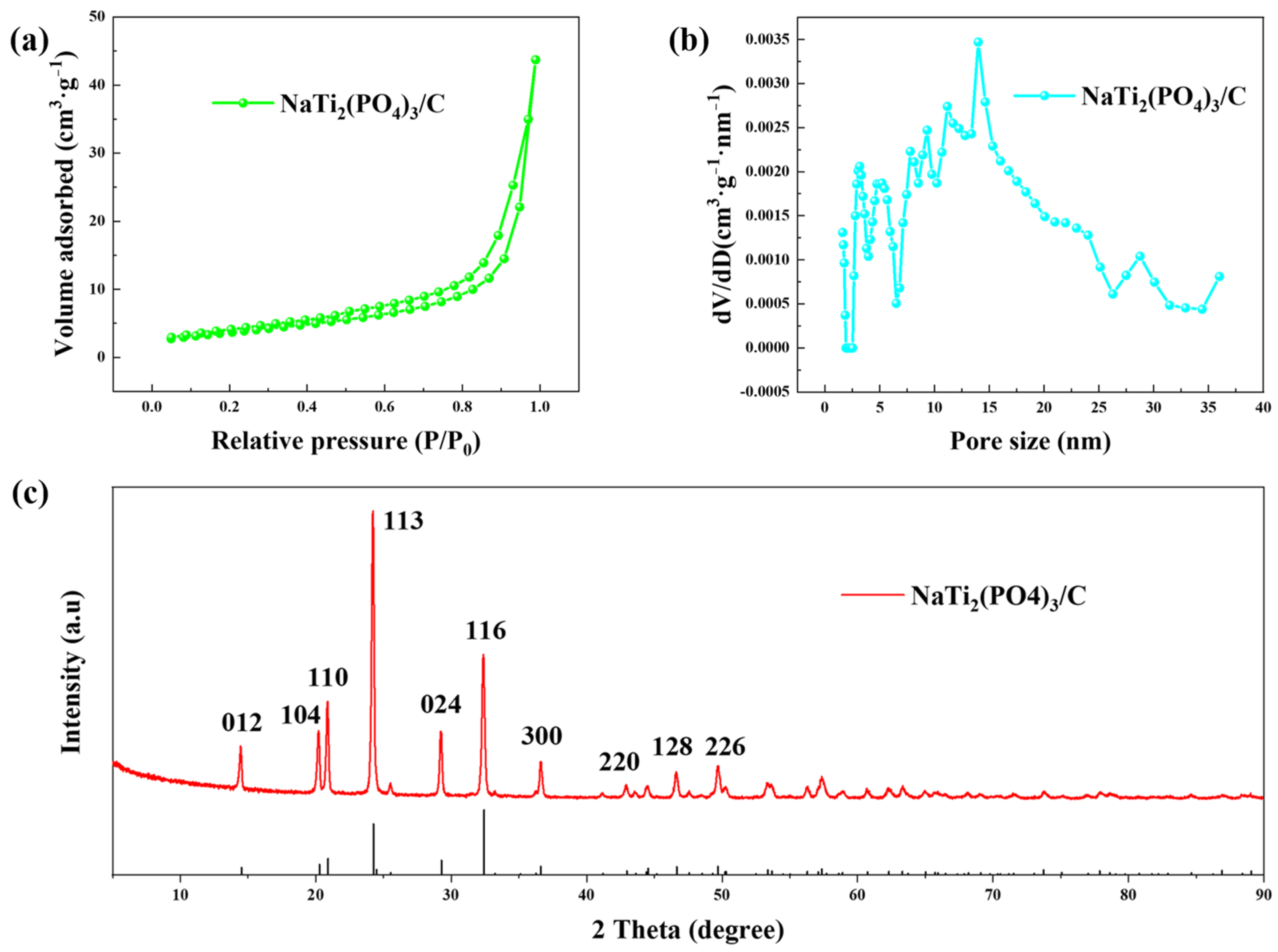
3.1. Characterization
3.2. Electrochemical Tests
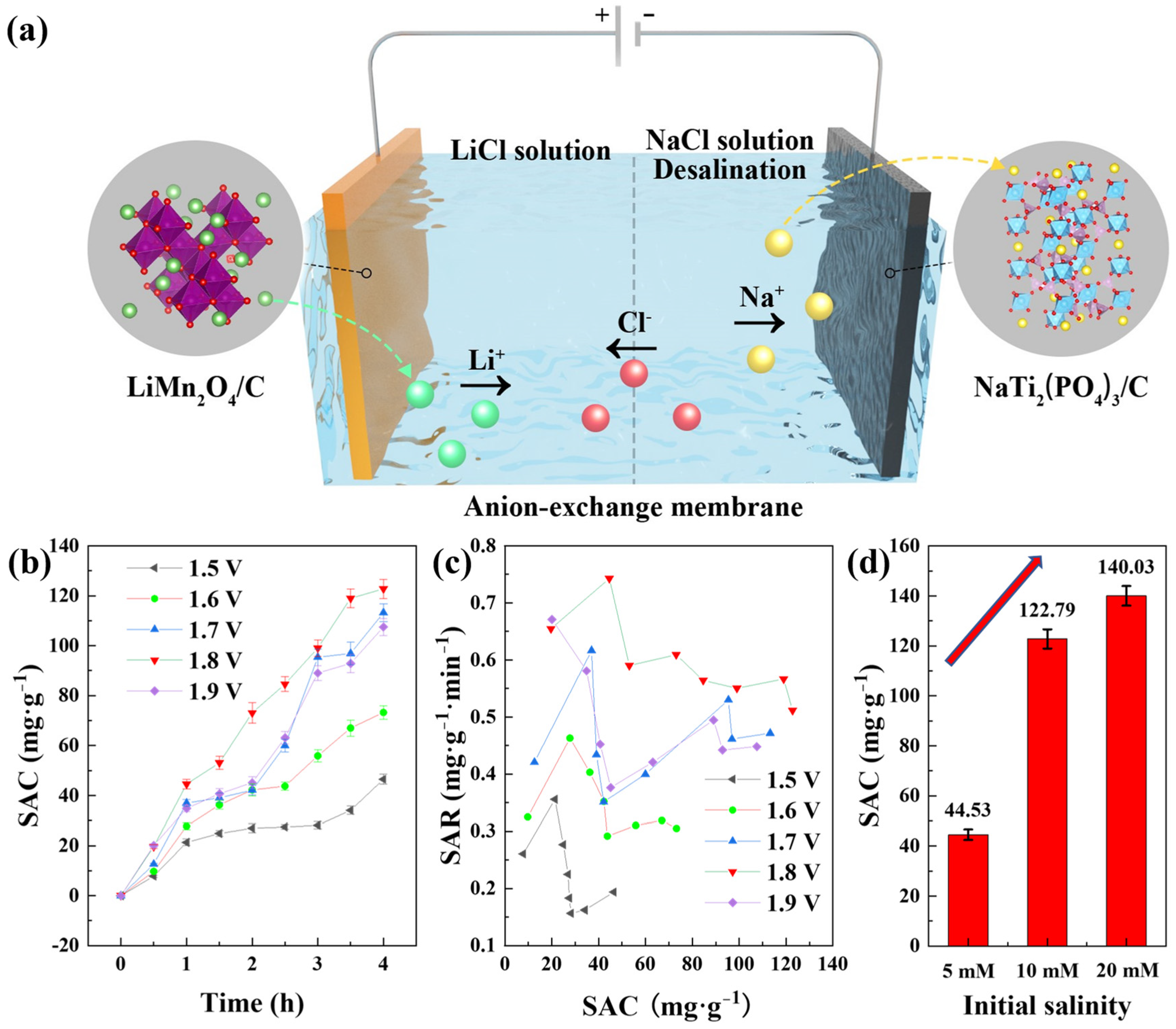
3.3. Desalination Performance
4. Conclusions
Supplementary Materials
Author Contributions
Funding
Institutional Review Board Statement
Conflicts of Interest
References
- Liu, X.H.; Mishra, D.D.; Wang, X.B.; Peng, H.Y.; Hu, C.Q. Towards highly efficient solar-driven interfacial evaporation for desalination. J. Mater. Chem. A 2020, 8, 17907–17937. [Google Scholar] [CrossRef]
- Hmtshirazi, R.; Mohammadi, T.; Asadi, A.A.; Tofighy, M.A. Electrospun nanofiber affinity membranes for water treatment applications: A review. J. Water Process Eng. 2022, 47, 102795. [Google Scholar] [CrossRef]
- Prajapati, M.; Shah, M.; Soni, B. A review of geothermal integrated desalination: A sustainable solution to overcome potential freshwater shortages. J. Clean. Prod. 2021, 326, 129412. [Google Scholar] [CrossRef]
- Ihsanullah, I.; Atieh, M.A.; Sajid, M.; Nazal, M.K. Desalination and environment: A critical analysis of impacts, mitigation strategies, and greener desalination technologies. Sci. Total Environ. 2021, 780, 146585. [Google Scholar] [CrossRef] [PubMed]
- Yan, Z.S.; Qu, F.S.; Liang, H.; Yu, H.R.; Pang, H.L.; Rong, H.W.; Fan, G.D.; Van der Bruggen, B. Effect of biopolymers and humic substances on gypsum scaling and membrane wetting during membrane distillation. J. Membr. Sci. 2021, 617, 118638. [Google Scholar] [CrossRef]
- Skuse, C.; Gallego-Schmid, A.; Azapagic, A.; Gorgojo, P. Can emerging membrane-based desalination technologies replace reverse osmosis? Desalination 2021, 500, 114844. [Google Scholar] [CrossRef]
- Zhang, H.R.; He, Q.M.; Luo, J.Q.; Wan, Y.H.; Darling, S.B. Sharpening Nanofiltration: Strategies for Enhanced Membrane Selectivity. ACS Appl. Mater. Interfaces 2020, 12, 39948–39966. [Google Scholar] [CrossRef]
- Nejati, S.; Mirbagheri, S.A.; Warsinger, D.M.; Fazeli, M. Biofouling in seawater reverse osmosis (SWRO): Impact of module geometry and mitigation with ultrafiltration. J. Water Process Eng. 2019, 29, 100782. [Google Scholar] [CrossRef]
- Elimelech, M.; Phillip, W.A. The Future of Seawater Desalination: Energy, Technology, and the Environment. Science 2011, 333, 712–717. [Google Scholar] [CrossRef]
- Porada, S.; Zhao, R.; van der Wal, A.; Presser, V.; Biesheuvel, P.M. Review on the science and technology of water desalination by capacitive deionization. Prog. Mater. Sci. 2013, 58, 1388–1442. [Google Scholar] [CrossRef]
- Folaranmi, G.; Bechelany, M.; Sistat, P.; Cretin, M.; Zaviska, F. Towards Electrochemical Water Desalination Techniques: A Review on Capacitive Deionization, Membrane Capacitive Deionization and Flow Capacitive Deionization. Membranes 2020, 10, 96. [Google Scholar] [CrossRef] [PubMed]
- Al Radi, M.; Sayed, E.T.; Alawadhi, H.; Abdelkareem, M.A. Progress in energy recovery and graphene usage in capacitive deionization. Crit. Rev. Environ. Sci. Technol. 2021, 52, 3080–3136. [Google Scholar] [CrossRef]
- Samimi, F.; Ghiyasiyan-Arani, M.; Salavati-Niasari, M. New avenue for preparation of potential hydrogen storage materials based on K10 montmorillonite and Ca2Mn3O8/CaMn3O6 nanocomposites. Fuel 2022, 320, 123933. [Google Scholar] [CrossRef]
- Liu, X.T.; Shanbhag, S.; Mauter, M.S. Understanding and mitigating performance decline in electrochemical deionization. Curr. Opin. Chem. Eng. 2019, 25, 67–74. [Google Scholar] [CrossRef]
- Srimuk, P.; Su, X.; Yoon, J.; Aurbach, D.; Presser, V. Charge-transfer materials for electrochemical water desalination, ion separation and the recovery of elements. Nat. Rev. Mater. 2020, 5, 517–538. [Google Scholar] [CrossRef]
- Baroud, T.N.; Giannelis, E.P. High salt capacity and high removal rate capacitive deionization enabled by hierarchical porous carbons. Carbon 2018, 139, 614–625. [Google Scholar] [CrossRef]
- Li, Y.J.; Liu, Y.; Wang, M.; Xu, X.T.; Lu, T.; Sun, C.Q.; Pan, L.K. Phosphorus-doped 3D carbon nanofiber aerogels derived from bacterial-cellulose for highly-efficient capacitive deionization. Carbon 2018, 130, 377–383. [Google Scholar] [CrossRef]
- Elisadiki, J.; King’ondu, C.K. Performance of ion intercalation materials in capacitive deionization/electrochemical deionization: A review. J. Electroanal. Chem. 2020, 878, 114588. [Google Scholar]
- Li, Q.; Zheng, Y.; Xiao, D.J.; Or, T.; Gao, R.; Li, Z.Q.; Feng, M.; Shui, L.L.; Zhou, G.F.; Wang, X.; et al. Faradaic Electrodes Open a New Era for Capacitive Deionization. Adv. Sci. 2020, 7, 2002213. [Google Scholar] [CrossRef]
- Lee, J.; Kim, S.; Kim, C.; Yoon, J. Hybrid capacitive deionization to enhance the desalination performance of capacitive techniques. Energy Environ. Sci. 2014, 7, 3683–3689. [Google Scholar] [CrossRef]
- Ahn, J.; Lee, J.; Kim, S.; Kim, C.; Lee, J.; Biesheuvel, P.M.; Yoon, J. High performance electrochemical saline water desalination using silver and silver-chloride electrodes. Desalination 2020, 476, 114216. [Google Scholar] [CrossRef]
- Yue, Z.S.; Gao, T.; Li, H.B. Robust synthesis of carbon@Na4Ti9O20 core-shell nanotubes for hybrid capacitive deionization with enhanced performance. Desalination 2019, 449, 69–77. [Google Scholar] [CrossRef]
- Tsujimoto, S.; Kondo, Y.; Yokoyama, Y.; Miyahara, Y.; Miyazaki, K.; Abe, T. Alkali Metal Ion Insertion and Extraction on Non-Graphitizable Carbon with Closed Pore Structures. J. Electrochem. Soc. 2021, 168, 070508. [Google Scholar] [CrossRef]
- Hong, S.Y.; Kim, Y.; Park, Y.; Choi, A.; Choi, N.S.; Lee, K.T. Charge carriers in rechargeable batteries: Na ions vs. Li ions. Energy Environ. Sci. 2013, 6, 2067–2081. [Google Scholar] [CrossRef]
- Jiang, Y.; Chai, L.; Zhang, D.; Ouyang, F.; Zhou, X.; Alhassan, S.I.; Liu, S.; He, Y.; Yan, L.; Wang, H.; et al. Facet-Controlled LiMn2O4/C as Deionization Electrode with Enhanced Stability and High Desalination Performance. Nano-Micro Lett. 2022, 14, 176. [Google Scholar] [CrossRef]
- Ghiyasiyan-Arani, M.; Salayati-Niasari, M. Effect of Li2CoMn3O8 Nanostructures Synthesized by a Combustion Method on Montmorillonite K10 as a Potential Hydrogen Storage Material. J. Phys. Chem. C 2018, 122, 16498–16509. [Google Scholar] [CrossRef]
- Ghiyasiyan-Arani, M.; Salavati-Niasari, M. Synergic and coupling effect between SnO2 nanoparticles and hierarchical AlV3O9 microspheres toward emerging electrode materials for lithium-ion battery devices. Inorg. Chem. Front. 2021, 8, 2735–2748. [Google Scholar] [CrossRef]
- Wu, M.G.; Ni, W.; Hu, J.; Ma, J.M. NASICON-Structured NaTi2(PO4)3 for Sustainable Energy Storage. Nano-Micro Lett. 2019, 11, 44. [Google Scholar] [CrossRef] [Green Version]
- Fu, L.; Xue, X.; Tang, Y.G.; Sun, D.; Xie, H.L.; Wang, H.Y. Size controlling and surface engineering enable NaTi2(PO4)3/C outstanding sodium storage properties. Electrochim. Acta 2018, 289, 21–28. [Google Scholar] [CrossRef]
- Zhang, X.; Dong, M.; Xiong, Y.; Hou, Z.; Qian, Y. Aqueous Rechargeable Li+ /Na+ Hybrid Ion Battery with High Energy Density and Long Cycle Life. Small 2020, 16, 2003585. [Google Scholar] [CrossRef]
- Chen, Z.Q.; Xu, X.T.; Ding, Z.B.; Wang, K.; Sun, X.; Lu, T.; Konarova, M.; Eguchi, M.; Shapter, J.G.; Pan, L.K.; et al. Ti3C2 MXenes-derived NaTi2(PO4)3/MXene nanohybrid for fast and efficient hybrid capacitive deionization performance. Chem. Eng. J. 2021, 407, 127148. [Google Scholar] [CrossRef]
- Srimuk, P.; Lee, J.; Tolosa, A.; Kim, C.; Aslan, M.; Presser, V. Titanium Disulfide: A Promising Low-Dimensional Electrode Material for Sodium Ion Intercalation for Seawater Desalination. Chem. Mat. 2017, 29, 9964–9973. [Google Scholar] [CrossRef]
- Kim, S.; Lee, J.; Kim, C.; Yoon, J. Na2FeP2O7 as a Novel Material for Hybrid Capacitive Deionization. Electrochim. Acta 2016, 203, 265–271. [Google Scholar] [CrossRef]
- Tan, J.F.; Zhu, W.H.; Gui, Q.Y.; Li, Y.Y.; Liu, J.P. Weak Ionization Induced Interfacial Deposition and Transformation towards Fast-Charging NaTi2(PO4)3 Nanowire Bundles for Advanced Aqueous Sodium-Ion Capacitors. Adv. Funct. Mater. 2021, 31, 2101027. [Google Scholar] [CrossRef]
- Zhao, M.Y.; Ji, Z.Y.; Zhang, Y.G.; Guo, Z.Y.; Zhao, Y.Y.; Liu, J.; Yuan, J.S. Study on lithium extraction from brines based on LiMn2O4/Li1-xMn2O4 by electrochemical method. Electrochim. Acta 2017, 252, 350–361. [Google Scholar] [CrossRef]
- Guerfi, A.; Trottier, J.; Gagnon, C.; Barray, F.; Zaghib, K. High rechargeable sodium metal-conducting polymer batteries. J. Power Source 2016, 335, 131–137. [Google Scholar] [CrossRef]
- Kubota, K.; Dahbi, M.; Hosaka, T.; Kumakura, S.; Komaba, S. Towards K-Ion and Na-Ion Batteries as “Beyond Li-Ion”. Chem. Rec. 2018, 18, 459–479. [Google Scholar] [CrossRef] [PubMed]
- Natarajan, S.; Subramanyan, K.; Aravindan, V. Focus on Spinel Li4Ti5O12 as Insertion Type Anode for High-Performance Na-Ion Batteries. Small 2019, 15, 1904484. [Google Scholar] [CrossRef] [PubMed]
- Wang, S.; Wang, D.Z.; Ji, L.J.; Gong, Q.M.; Zhu, Y.F.; Liang, J. Equilibrium and kinetic studies on the removal of NaCl from aqueous solutions by electrosorption on carbon nanotube electrodes. Sep. Purif. Technol. 2007, 58, 12–16. [Google Scholar] [CrossRef]
- Xing, F.; Li, T.; Li, J.Y.; Zhu, H.R.; Wang, N.; Cao, X. Chemically exfoliated MoS2 for capacitive deionization of saline water. Nano Energy 2017, 31, 590–595. [Google Scholar] [CrossRef]
- Porada, S.; Shrivastava, A.; Bukowska, P.; Biesheuvel, P.M.; Smith, K.C. Nickel Hexacyanoferrate Electrodes for Continuous Cation Intercalation Desalination of Brackish Water. Electrochim. Acta 2017, 255, 369–378. [Google Scholar] [CrossRef]
- Liu, Z.Z.; Yue, Z.S.; Li, H.B. Na0.71CoO2 promoted sodium uptake via faradaic reaction for highly efficient capacitive deionization. Sep. Purif. Technol. 2020, 234, 116090. [Google Scholar] [CrossRef]
- Vafakhah, S.; Guo, L.; Sriramulu, D.; Huang, S.; Saeedikhani, M.; Yang, H.Y. Efficient sodium-ion intercalation into the freestanding Prussian blue/graphene aerogel anode in a hybrid capacitive deionization system. ACS Appl. Mater. Interfaces 2019, 11, 5989–5998. [Google Scholar] [CrossRef] [PubMed]
- Chang, J.J.; Duan, F.; Su, C.L.; Li, Y.P.; Cao, H.B. Removal of chloride ions using a bismuth electrode in capacitive deionization (CDI). Environ. Sci. Wat. Res. Technol. 2020, 6, 373–382. [Google Scholar] [CrossRef]
- Srimuk, P.; Halim, J.; Lee, J.; Tao, Q.Z.; Rosen, J.; Presser, V. Two-Dimensional Molybdenum Carbide (MXene) with Divacancy Ordering for Brackish and Seawater Desalination via Cation and Anion Intercalation. ACS Sustain. Chem. Eng. 2018, 6, 3739–3747. [Google Scholar] [CrossRef] [Green Version]
- Miao, L.W.; Wang, Z.; Peng, J.; Deng, W.Y.; Chen, W.Q.; Dai, Q.Z.; Ueyama, T. Pseudocapacitive deionization with polypyrrole grafted CMC carbon aerogel electrodes. Sep. Purif. Technol. 2022, 296, 121441. [Google Scholar] [CrossRef]
- Li, Y.L.; Cai, Y.M.; Wang, Y.; Liu, D.X.; Guo, J.Q. A Study of 3D flake MnO2 nanoflower decorated hollow carbon spheres as cathode material for pseudo-capacitive deionization. J. Environ. Chem. Eng. 2022, 10, 107266. [Google Scholar] [CrossRef]
- Zhao, W.Y.; Guo, L.; Ding, M.; Huang, Y.X.; Yang, H.Y. Ultrahigh-Desalination-Capacity Dual-Ion Electrochemical Deionization Device Based on Na3V2(PO4)3@C-AgCl Electrodes. ACS Appl. Mater. Interfaces 2018, 10, 40540–40548. [Google Scholar] [CrossRef]
- Ahsan, M.T.; Ali, Z.; Usman, M.; Hou, Y.L. Unfolding the structural features of NASICON materials for sodium-ion full cells. Carbon Energy 2022, 4, 776–819. [Google Scholar] [CrossRef]
- Yang, C.X.; Deng, Y.F.; Gao, M.; Yang, X.F.; Qin, X.S.; Chen, G.H. High-rate and long-life performance of a truncated spinel cathode material with off-stoichiometric composition at elevated temperature. Electrochim. Acta 2017, 225, 198–206. [Google Scholar] [CrossRef]
- Liu, Z.X.; An, Y.F.; Pang, G.; Dong, S.Y.; Xu, C.Y.; Mi, C.H.; Zhang, X.G. TiN modified NaTi2(PO4)3 as an anode material for aqueous sodium ion batteries. Chem. Eng. J. 2018, 353, 814–823. [Google Scholar] [CrossRef]


| Electrode Couple | Charging Mode | Electric Intensity | Initial Salinity | CDI Capacity | Ref. |
|---|---|---|---|---|---|
| CNT||CNT | CV | 1.2 V | 3500 ppm | 9.35 mg·g−1 | [39] |
| porous carbon||porous carbon | CV | 1.2 V | 292 ppm | 12.63 mg·g−1 | [16] |
| MoS2||AC | CV | 1.2 V | 400 mM | 8.81 mg·g−1 | [40] |
| Na4Mn9O18||AC | CV | 1.2 V | 50 mM | 31.2 mg·g−1 | [20] |
| NaNiFe(CN)6||Na2NiFe(CN)6 | constant current (CC) | 0.28 mA·cm−2 | 20 mM | 34 mg·g−1 | [41] |
| Na4Ti9O20/C||AC | CV | 1.4 V | 1000 ppm | 66.14 mg·g−1 | [22] |
| Na0.71CoO2||Ag/rGO | CV | 1.4 V | 500 ppm | 31 mg·g−1 | [42] |
| Fe4[Fe(CN)6]3/rGO || rGO | CC | 0.1 A·g−1 | 2500 ppm | 80 mg·g−1 | [43] |
| AC||Bi | CV | 1.2 V | 500 ppm | 55.52 mg·g−1 | [44] |
| Mo1.33C-MXene/CNT||Mo1.33C-MXene/CNT | CV | 0.8 V | 600 mM | 15 mg·g−1 | [45] |
| polypyrrole/C||polypyrrole/C | CV | 1.2 V | 500 ppm | 34.03 mg·g−1 | [46] |
| MnO2/C||MnO2/C | CV | 1.2 V | 500 ppm | 30.86 mg·g−1 | [47] |
| Na3V2(PO4)3/C||AgCl | CC | 0.1 A·g−1 | 1000 ppm | 98.0 mg·g−1 | [48] |
| Ag||AgCl | CC | 1 mA·cm−2 | 500 mM | 85 mg·g−1 | [22] |
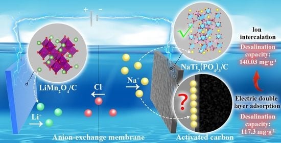
| LiMn2O4/C||AC | CV | 1.0 V | 20 mM | 117.3 mg·g−1 | [25] |
| LiMn2O4/C||NaTi2(PO4)3/C | CV | 1.8 V | 20 mM | 140.03 mg·g−1 | this work |
Publisher’s Note: MDPI stays neutral with regard to jurisdictional claims in published maps and institutional affiliations. |
© 2022 by the authors. Licensee MDPI, Basel, Switzerland. This article is an open access article distributed under the terms and conditions of the Creative Commons Attribution (CC BY) license (https://creativecommons.org/licenses/by/4.0/).
Share and Cite
Jiang, Y.; Hou, Z.; Yan, L.; Gang, H.; Wang, H.; Chai, L. A Novel Dual-Ion Capacitive Deionization System Design with Ultrahigh Desalination Performance. Polymers 2022, 14, 4776. https://doi.org/10.3390/polym14214776
Jiang Y, Hou Z, Yan L, Gang H, Wang H, Chai L. A Novel Dual-Ion Capacitive Deionization System Design with Ultrahigh Desalination Performance. Polymers. 2022; 14(21):4776. https://doi.org/10.3390/polym14214776
Chicago/Turabian StyleJiang, Yuxin, Zhiguo Hou, Lvji Yan, Haiyin Gang, Haiying Wang, and Liyuan Chai. 2022. "A Novel Dual-Ion Capacitive Deionization System Design with Ultrahigh Desalination Performance" Polymers 14, no. 21: 4776. https://doi.org/10.3390/polym14214776