
Strain Optimization of Tensioned Web through Computational Fluid Dynamics in the Roll-to-Roll Drying Process

 , ,
, , 
Abstract
:1. Introduction
2. Materials and Methods
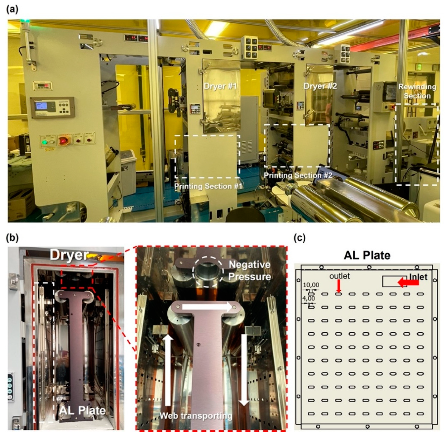
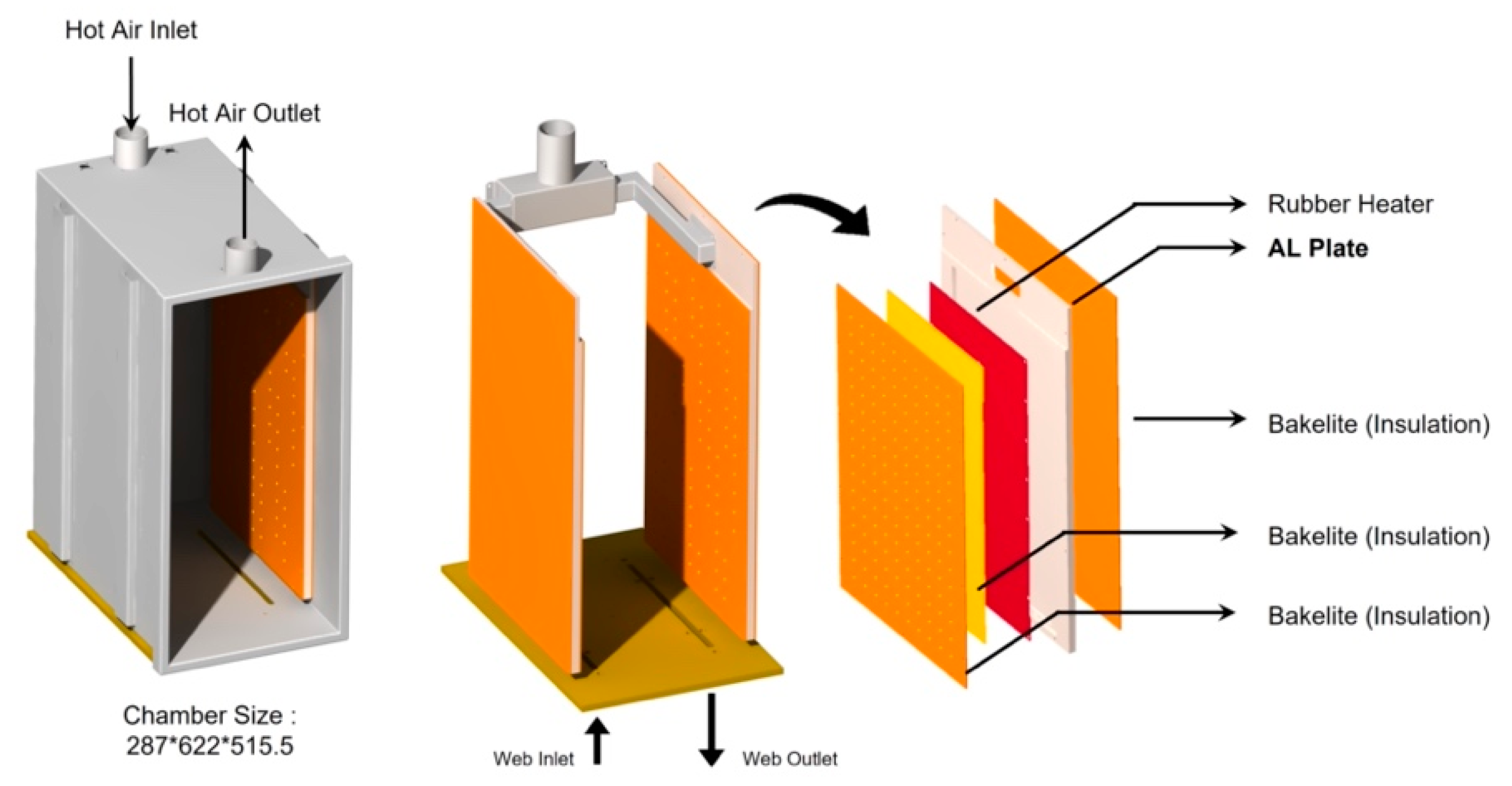
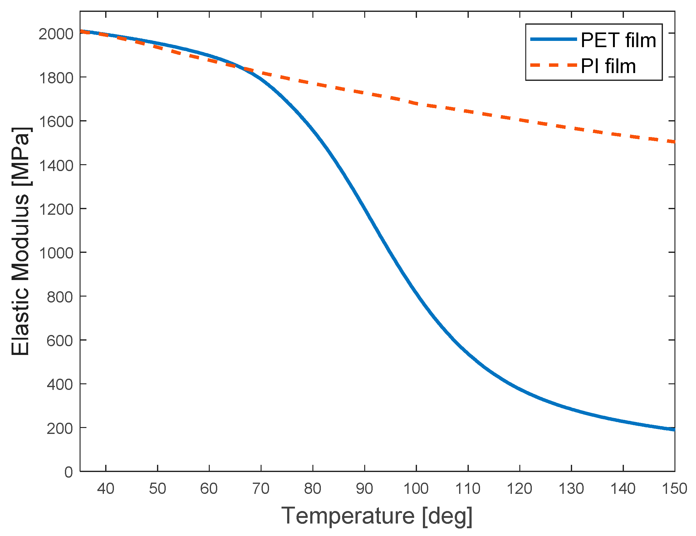
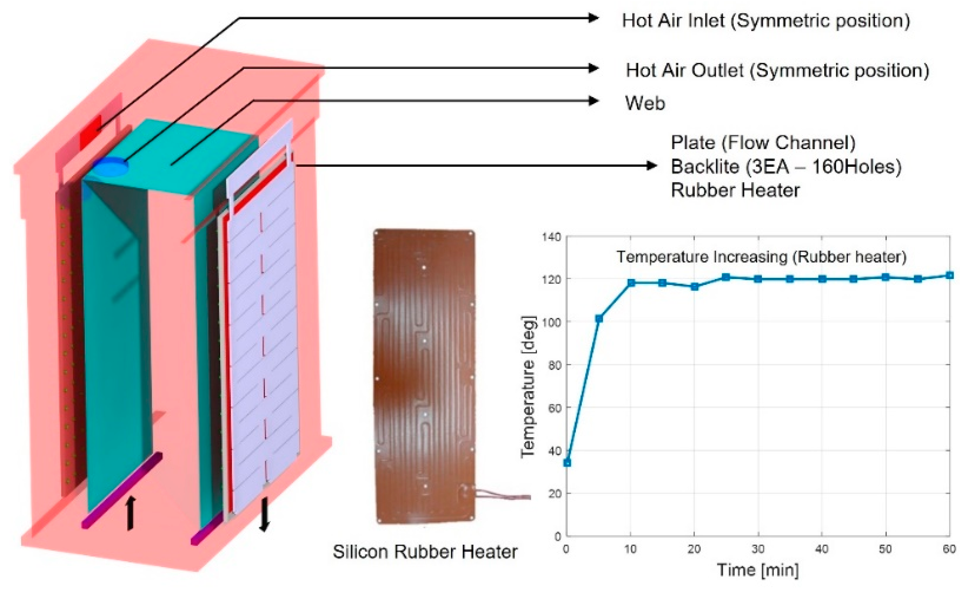
2.1. R2R System and Materials for the Polymer-Based Web
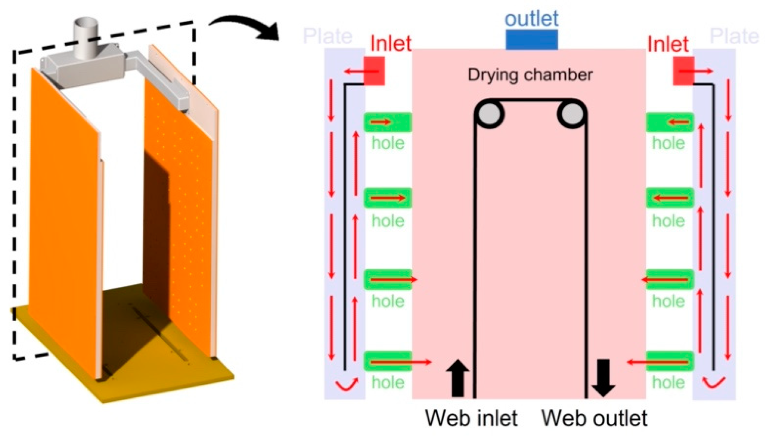
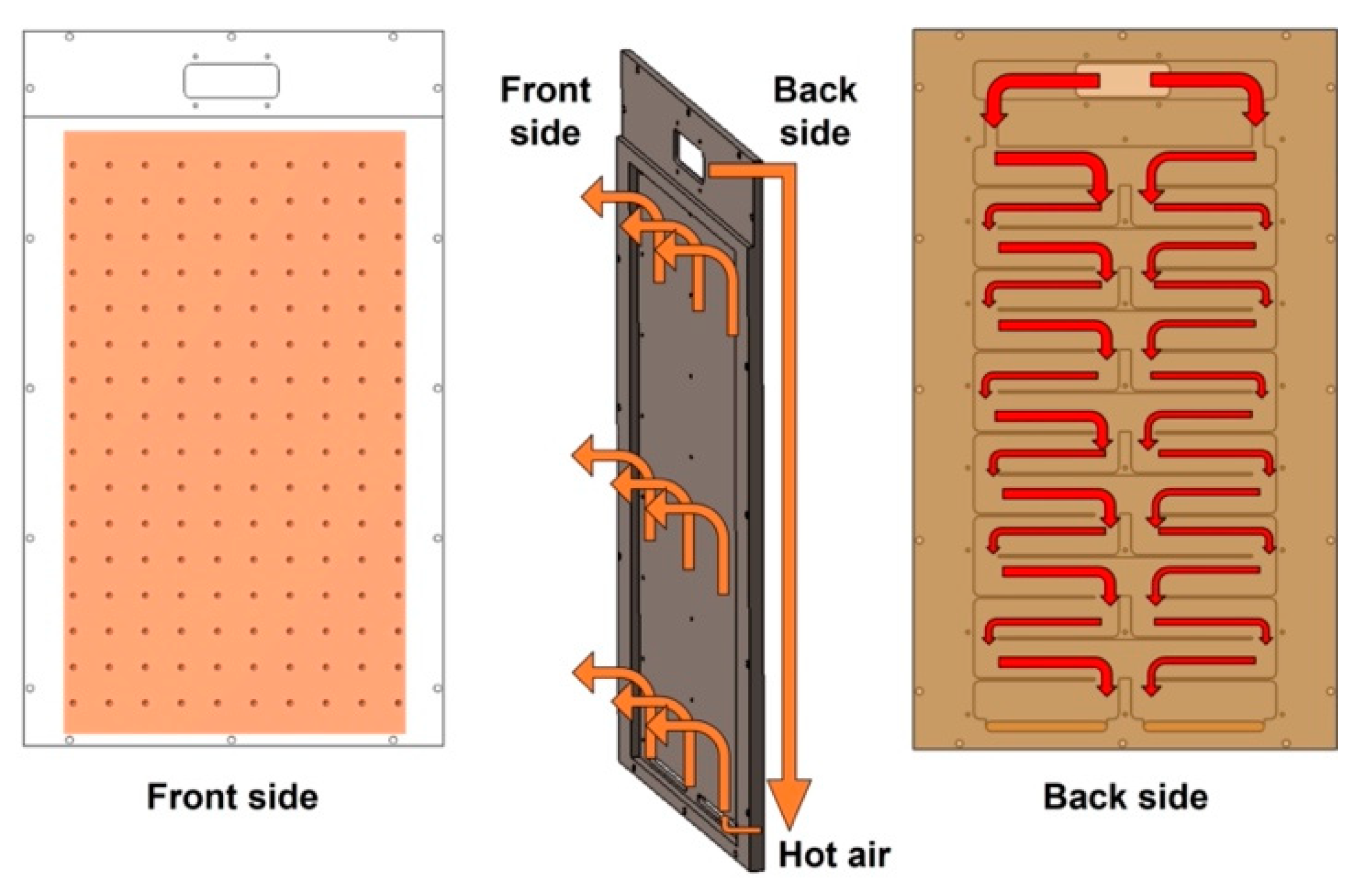
2.2. Computational Fluid Dynamics to Estimate the Temperature Distribution in the Drying Chamber
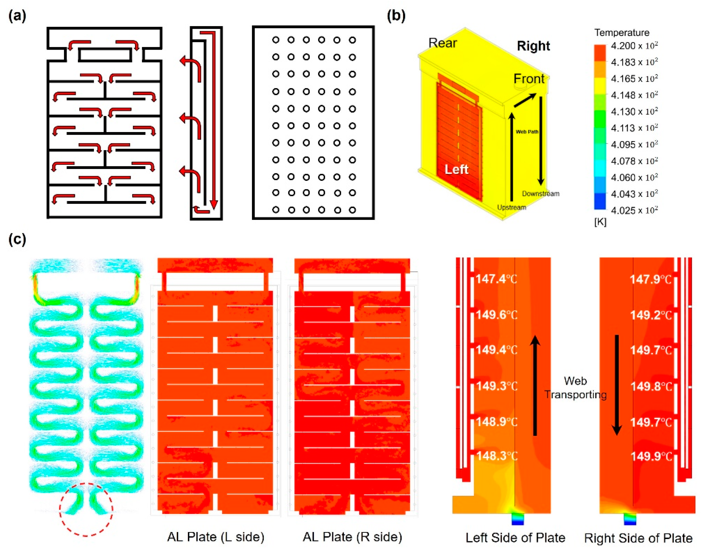
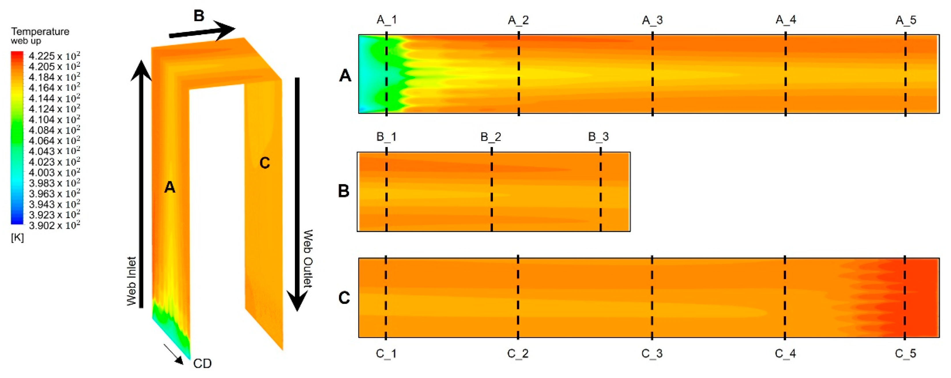
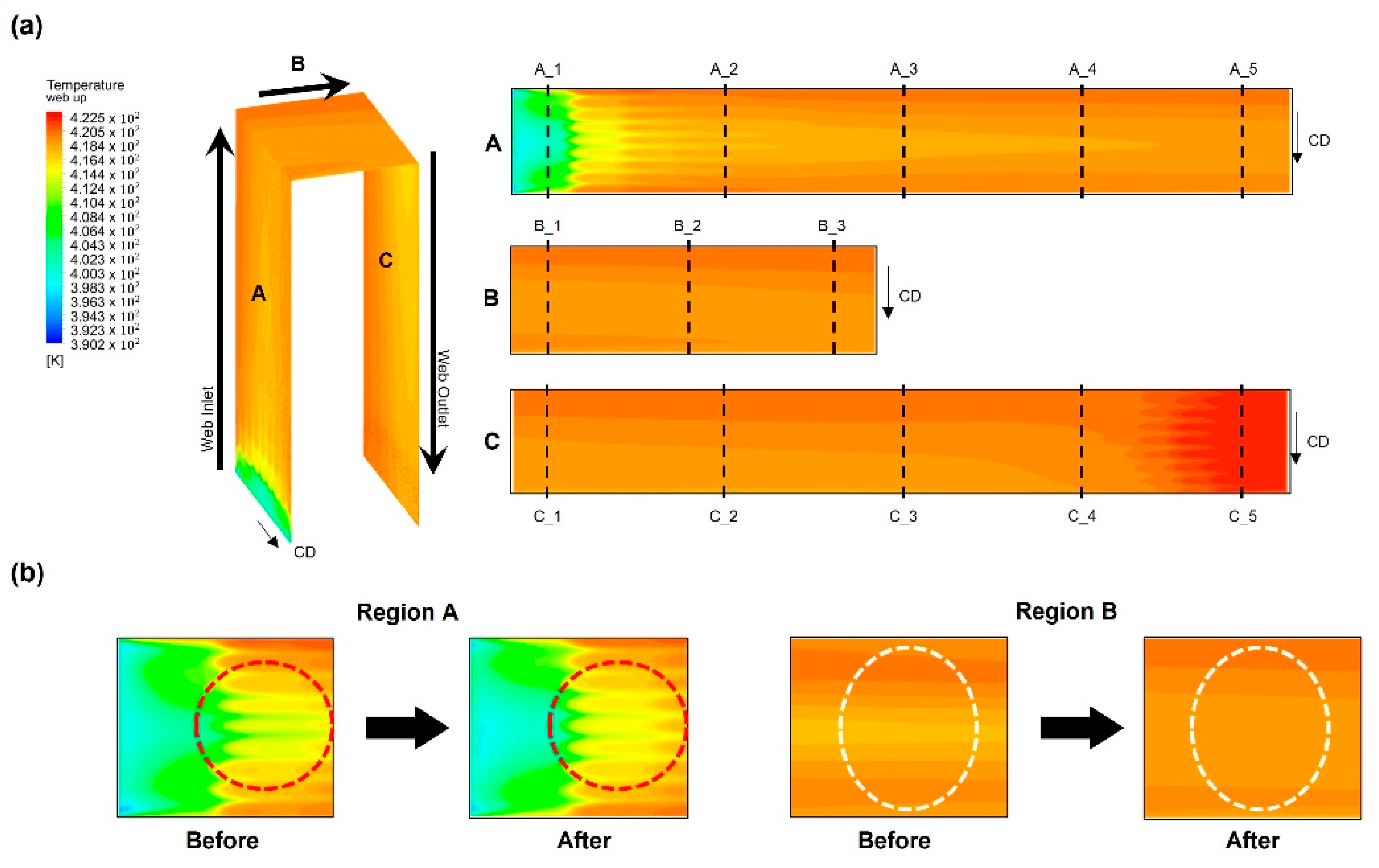
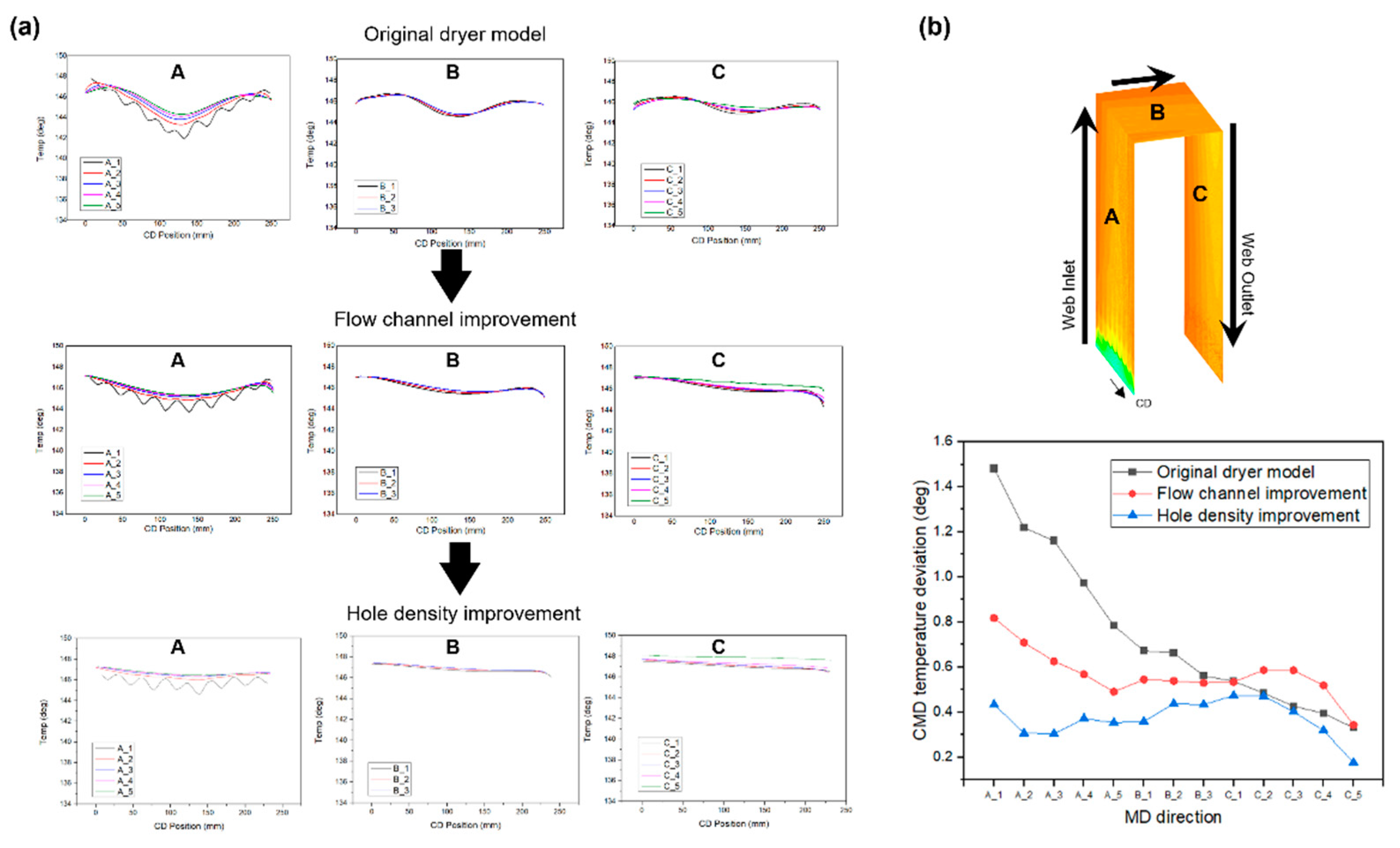
2.2.1. Analysis of the Temperature Distribution in the Original Dryer Model
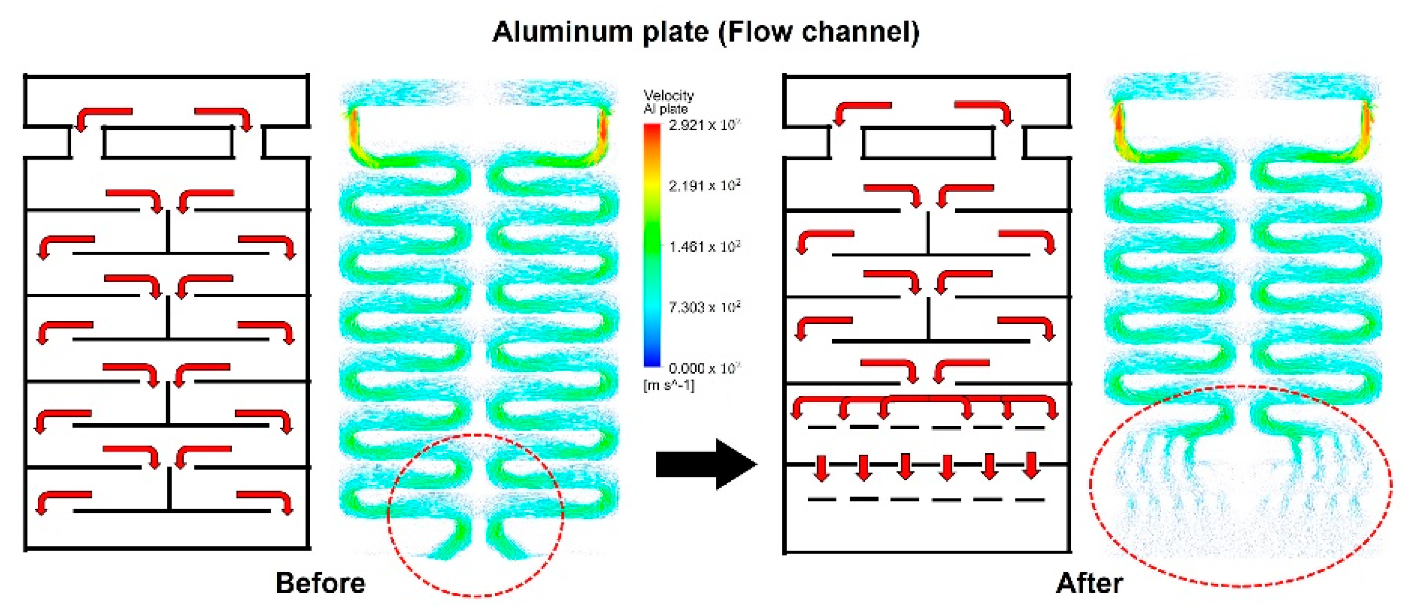
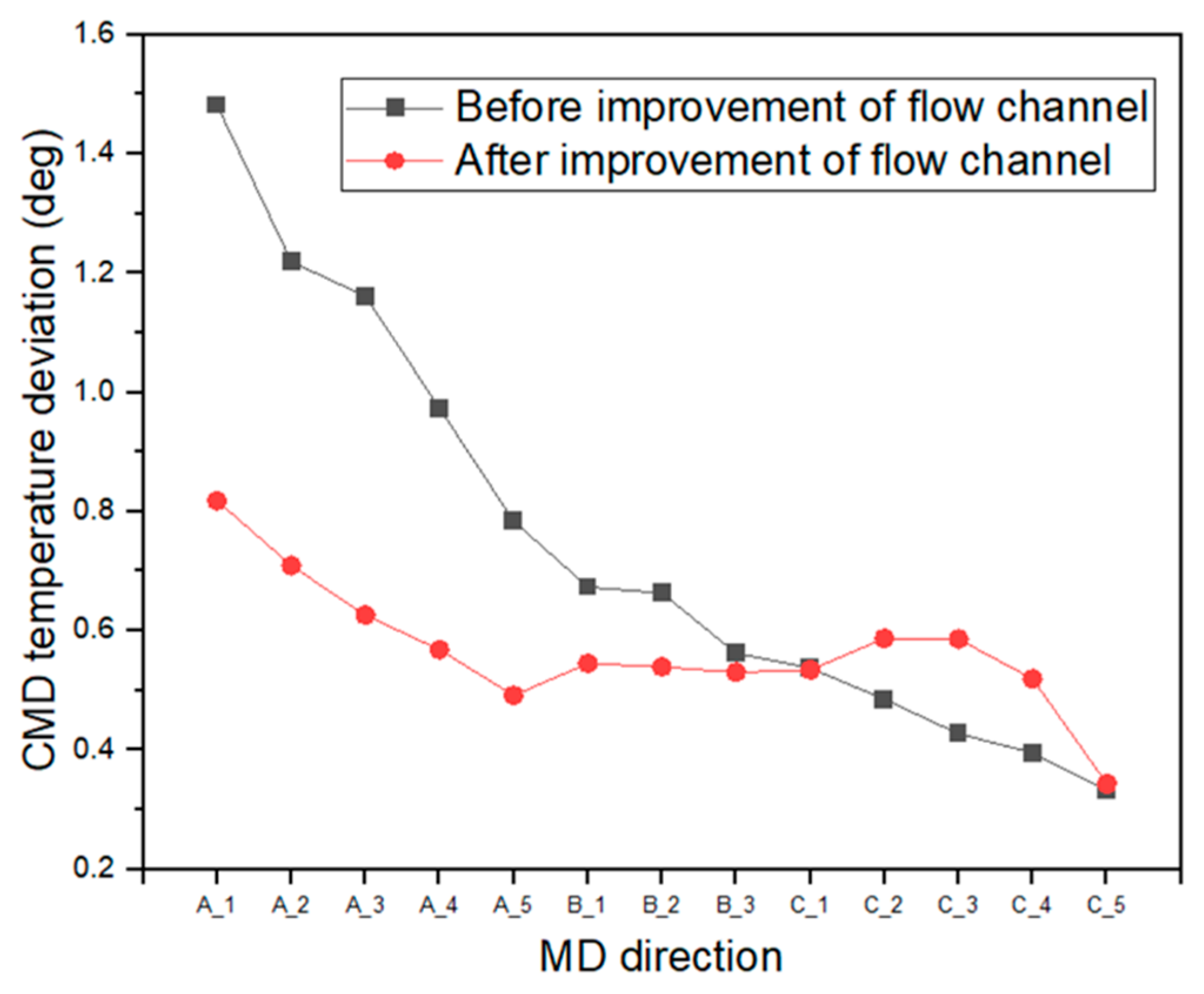
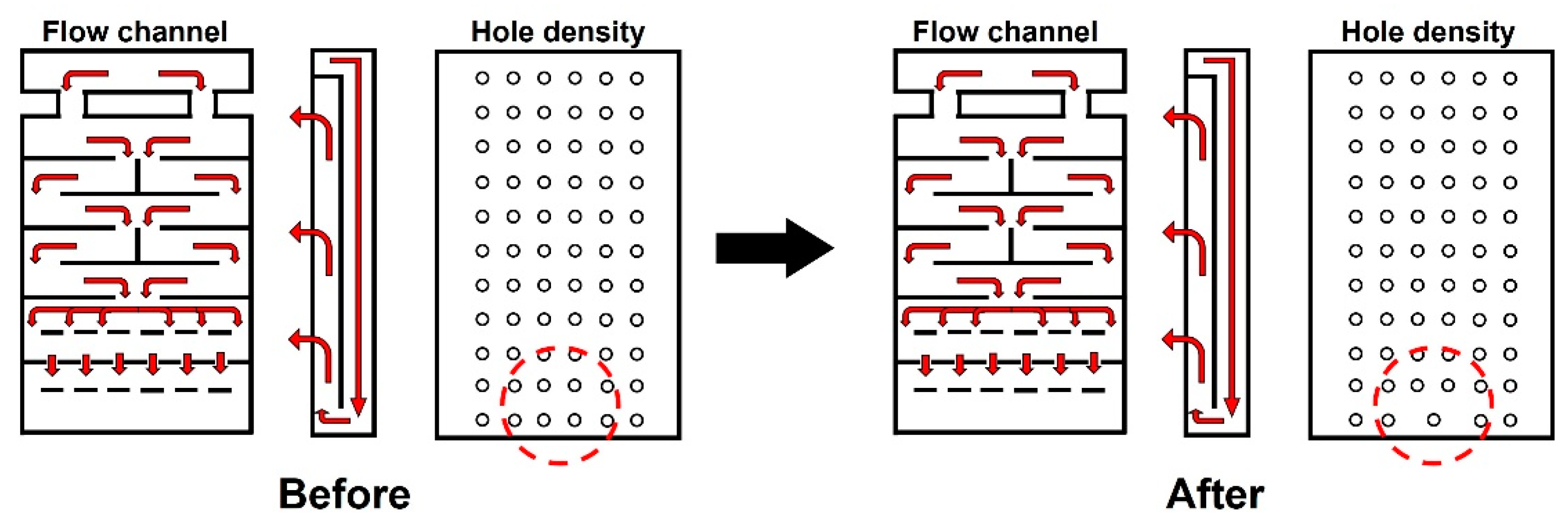
2.2.2. Improvements in the Dryer Structure to Achieve a Uniform Temperature Distribution in the Web
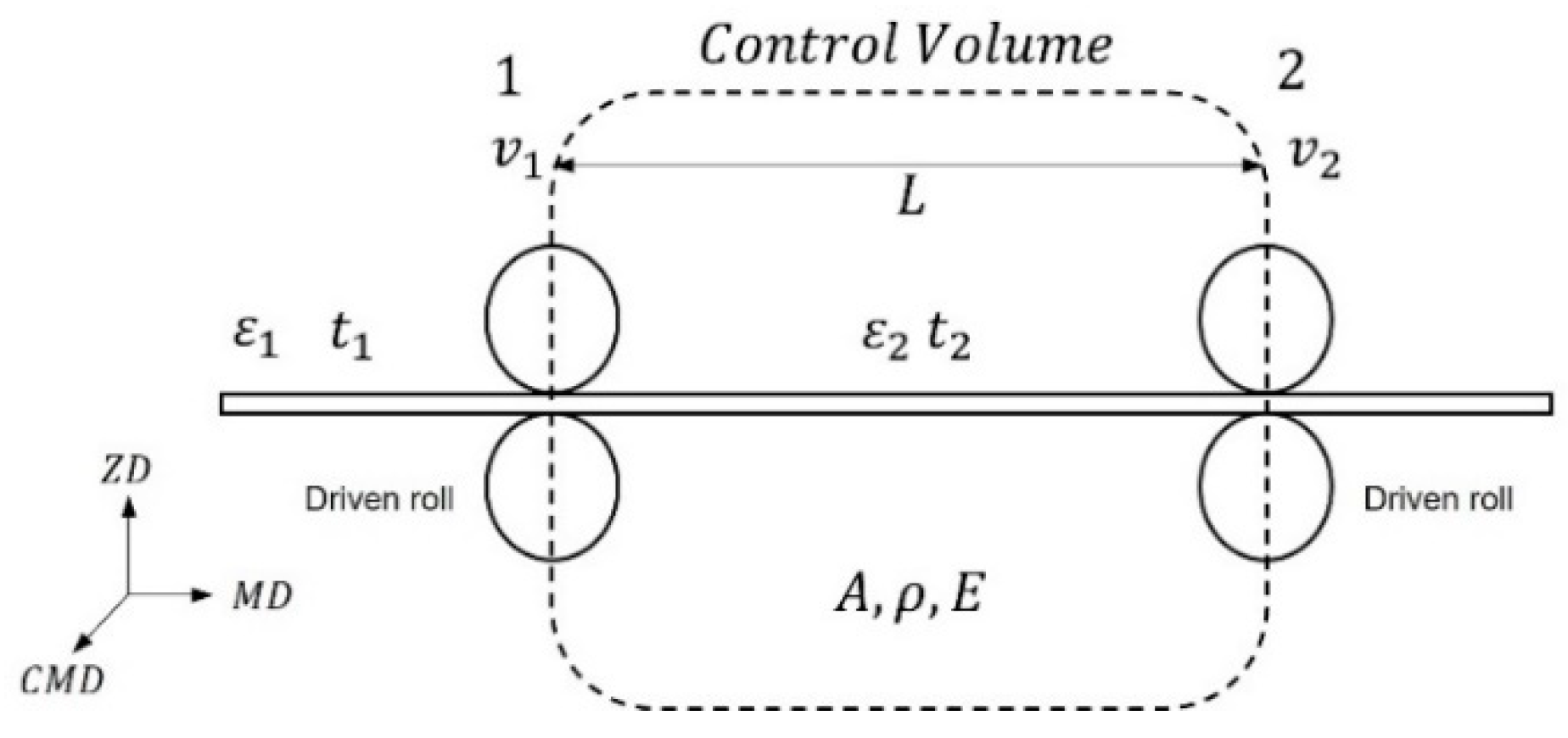
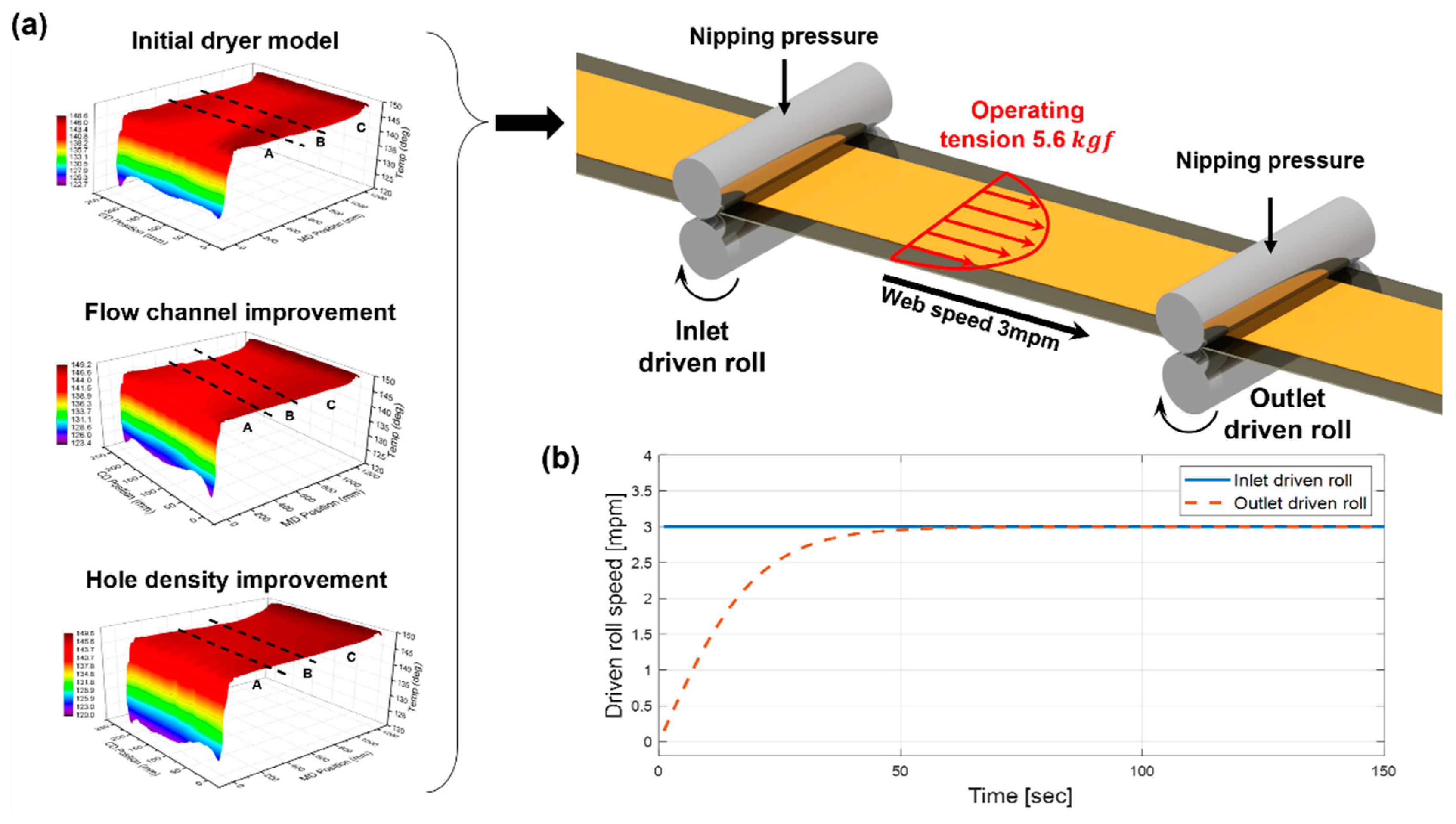
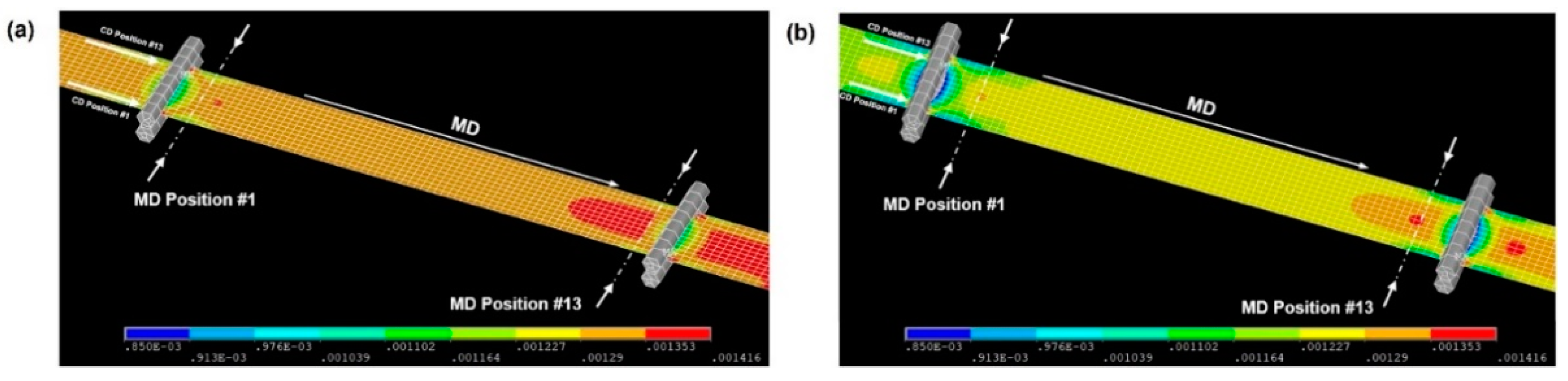
2.3. Structural Analysis to Estimate the Strain Distribution of the Moving Web in the Drying Chamber
3. Results and Discussion
4. Conclusions
Author Contributions
Funding
Institutional Review Board Statement
Informed Consent Statement
Data Availability Statement
Conflicts of Interest
References
- Tahir, U.; Kim, J.I.; Javeed, S.; Khaliq, A.; Kim, J.H.; Kim, D.I.; Jeong, M.Y. Process Optimization for Manufacturing Functional Nanosurfaces by Roll-to-Roll Nanoimprint Lithography. Nanomaterials 2022, 12, 480. [Google Scholar] [CrossRef]
- Lee, M.; Parajuli, S.; Moon, H.; Song, R.; Lee, S.; Shrestha, S.; Park, J.; Yang, H.; Jung, Y.; Cho, G.; et al. Characterization of Silver Nanoparticle Inks toward Stable Roll-to-Roll Gravure Printing. Flex. Print. Electron. 2022, 7, 014003. [Google Scholar] [CrossRef]
- Yu, D.; Beckelmann, D.; Opsölder, M.; Schäfer, B.; Moh, K.; Hensel, R.; de Oliveira, P.W.; Arzt, E. Roll-to-Roll Manufacturing of Micropatterned Adhesives by Template Compression. Materials 2018, 12, 97. [Google Scholar] [CrossRef] [Green Version]
- Jo, M.; Kim, S.; Lee, C. Morphology Engineering for Compact Electrolyte Layer of Solid Oxide Fuel Cell with Roll-to-Roll Eco-Production. Int. J. Precis. Eng. Manuf. Green Technol. 2022, 9, 431–441. [Google Scholar] [CrossRef]
- Jeong, H.; Noh, Y.; Kim, G.Y.; Lee, H.; Lee, D. Roll-to-Roll Processed Silver Nanowire/Silicon Dioxide Microsphere Composite for High-Accuracy Flexible Touch Sensing Application. Surf. Interfaces 2022, 30, 101976. [Google Scholar] [CrossRef]
- Bae, S.; Kim, H.; Lee, Y.; Xu, X.; Park, J.S.; Zheng, Y.; Balakrishnan, J.; Lei, T.; Kim, H.R.; Song, Y.I.; et al. Roll-to-Roll Production of 30-Inch Graphene Films for Transparent Electrodes. Nat. Nanotechnol. 2010, 5, 574–578. [Google Scholar] [CrossRef] [Green Version]
- Othman, M.; Zheng, F.; Seeber, A.; Chesman, A.S.R.; Scully, A.D.; Ghiggino, K.P.; Gao, M.; Etheridge, J.; Angmo, D. Millimeter-Sized Clusters of Triple Cation Perovskite Enables Highly Efficient and Reproducible Roll-to-Roll Fabricated Inverted Perovskite Solar Cells. Adv. Funct. Mater. 2022, 32, 2110700. [Google Scholar] [CrossRef]
- Seong, J.; Park, J.; Lee, J.; Ahn, B.; Yeom, J.H.; Kim, J.; Hassinen, T.; Rhee, S.; Ko, S.; Lee, D.; et al. Practical Design Guidelines for the Development of High-Precision Roll-to-Roll Slot-Die Coating Equipment and the Process. IEEE Trans. Compon. Packag. Manuf. Technol. 2016, 6, 1677–1686. [Google Scholar] [CrossRef]
- Choi, H.; Jeong, S. A Review on Eco-Friendly Quantum Dot Solar Cells: Materials and Manufacturing Processes. Int. J. Precis. Eng. Manuf. Green Technol. 2018, 5, 349–358. [Google Scholar] [CrossRef]
- Sato, K.; Uchida, S.; Toriyama, S.; Nishimura, S.; Oyaizu, K.; Nishide, H.; Nishikitani, Y. Low-Cost, Organic Light-Emitting Electrochemical Cells with Mass-Producible Nanoimprinted Substrates Made Using Roll-to-Roll Methods. Adv. Mater. Technol. 2017, 2, 1600293. [Google Scholar] [CrossRef]
- Sun, J.; Park, H.; Jung, Y.; Rajbhandari, G.; Maskey, B.B.; Sapkota, A.; Azuma, Y.; Majima, Y.; Cho, G. Proving Scalability of an Organic Semiconductor to Print a TFT-Active Matrix Using a Roll-to-Roll Gravure. ACS Omega 2017, 2, 5766–5774. [Google Scholar] [CrossRef] [PubMed]
- Wonsyld, K.; Bech, L.; Nielsen, J.U.; Pedersen, C.F. Operational Robustness Studies of Solid Oxide Electrolysis Stacks. J. Energy Power Eng. 2015, 9, 128–140. [Google Scholar] [CrossRef] [Green Version]
- Jung, E.; Kim, C.; Kim, M.; Chae, H.; Cho, J.H.; Cho, S.M. Roll-to-Roll Preparation of Silver-Nanowire Transparent Electrode and Its Application to Large-Area Organic Light-Emitting Diodes. Org. Electron. 2017, 41, 190–197. [Google Scholar] [CrossRef]
- Park, H.; Sun, J.; Jung, Y.; Park, J.; Maskey, B.B.; Shrestha, K.; Koirala, G.R.; Parajuli, S.; Shrestha, S.; Chung, A.; et al. The First Step towards a R2R Printing Foundry via a Complementary Design Rule in Physical Dimension for Fabricating Flexible 4-Bit Code Generator. Adv. Electron. Mater. 2020, 6, 2000770. [Google Scholar] [CrossRef]
- Kim, Y.H.; Wolf, C.; Cho, H.; Jeong, S.H.; Lee, T.W. Highly Efficient, Simplified, Solution-Processed Thermally Activated Delayed-Fluorescence Organic Light-Emitting Diodes. Adv. Mater. 2016, 28, 734–741. [Google Scholar] [CrossRef]
- Huang, R.; Zhang, X.Q.; Ng, B.P.; Kumar, A.S.; Liu, K. Roll-to-Roll Embossing of Optical Radial Fresnel Lenses on Polymer Film for Concentrator Photovoltaics: A Feasibility Study. Int. J. Precis. Eng. Manuf. Green Technol. 2021, 8, 77–88. [Google Scholar] [CrossRef]
- Lee, S.H.; Lee, S. Fabrication of Comb-Structured Acceleration Sensors by Roll-to-Roll Gravure Printing. Int. J. Precis. Eng. Manuf. Green Technol. 2022, 9, 409–420. [Google Scholar] [CrossRef]
- Lu, Y.; Pagilla, P.R. Modeling of Temperature Distribution in Moving Webs in Roll-to-Roll Manufacturing. J. Therm. Sci. Eng. Appl. 2014, 6, 041012. [Google Scholar] [CrossRef]
- Lu, Y. Modeling the Effects of Heat Transfer Processes on Material Strain and Tension in Roll to Roll Manufacturing. In Proceedings of the Dynamic Systems and Control Conference, Palo Alto, CA, USA, 21–23 October 2013; p. V003T48A004. [Google Scholar]
- Lu, Y.; Pagilla, P.R. Adaptive Control of Web Tension in a Heat Transfer Section of a Roll-to-Roll Manufacturing Process Line. In Proceedings of the 2014 American Control Conference, Portland, OR, USA, 4–6 June 2014; IEEE: Manhattan, NY, USA; American Automatic Control Council: Dayton, IL, USA, 2014; pp. 1799–1804. [Google Scholar]
- Park, J.; Nguyen, H.A.; Park, S.; Lee, J.; Kim, B.; Lee, D. Roll-to-Roll Gravure Printed Silver Patterns to Guarantee Printability and Functionality for Mass Production. Curr. Appl. Phys. 2015, 15, 367–376. [Google Scholar] [CrossRef]
- Keränen, K.; Korhonen, P.; Rekilä, J.; Tapaninen, O.; Happonen, T.; Makkonen, P.; Rönkä, K. Roll-to-Roll Printed and Assembled Large Area LED Lighting Element. Int. J. Adv. Manuf. Technol. 2015, 81, 529–536. [Google Scholar] [CrossRef] [Green Version]
- Lynch, A.F.; Bortoff, S.A.; Röbenack, K. Nonlinear Tension Observers for Web Machines. Automatica 2004, 40, 1517–1524. [Google Scholar] [CrossRef]
- Avci, A.; Can, M.; Etemoglu, A.B. A Theoretical Approach to the Drying Process of Thin Film Layers. Appl. Therm. Eng. 2001, 21, 465–479. [Google Scholar] [CrossRef]
- Lu, Y.; Pagilla, P.R. A Nonlinear Tension Control Scheme for Web Transport through Heating Processes. In Proceedings of the ASME 2015 Dynamic Systems and Control Conference, DSCC 2015, Columbus, OH, USA, 28–30 October 2015; Volume 57250, p. V002T32A006. [Google Scholar]
- Knepper, R.; Baker, S.P. Coefficient of Thermal Expansion and Biaxial Elastic Modulus of Β Phase Tantalum Thin Films. Appl. Phys. Lett. 2007, 90, 181908. [Google Scholar] [CrossRef]
- Choy, C.L.; Wong, Y.W.; Yang, G.W. Elastic Modulus and Thermal Conductivity of Ultra-Oriented Polyethylene. Acta Polym. Sin. 1997, 37, 341–342. [Google Scholar]
- Barker, R.E. An Approximate Relation between Elastic Moduli and Thermal Expansivities. J. Appl. Phys. 1963, 34, 107–116. [Google Scholar] [CrossRef]
- Feng, D.; Raman, A. Thermomechanics of Axially Moving Webs in Roll-to-Roll Manufacturing Processes. Int. J. Heat Mass Transf. 2019, 129, 1317–1327. [Google Scholar] [CrossRef]
- Jo, M.; Lee, J.; Kim, S.; Cho, G.; Lee, T.M.; Lee, C. Web Unevenness Due to Thermal Deformation in the Roll-to-roll Manufacturing Process. Appl. Sci. 2020, 10, 8636. [Google Scholar] [CrossRef]
- Jo, M.; Kim, S.; Cho, G.; Lee, T.M.; Lee, J.; Lee, C. Achieving Specified Geometric Quality in a Fully Printed Flexible Functional Layer Using Process Parameters in Roll-to-Roll Printed Electronics. Flex. Print. Electron. 2022, 7, 014007. [Google Scholar] [CrossRef]
- Khan, Y.; Garg, M.; Gui, Q.; Schadt, M.; Gaikwad, A.; Han, D.; Yamamoto, N.A.D.; Hart, P.; Welte, R.; Wilson, W.; et al. Flexible Hybrid Electronics: Direct Interfacing of Soft and Hard Electronics for Wearable Health Monitoring. Adv. Funct. Mater. 2016, 26, 8764–8775. [Google Scholar] [CrossRef]
- Lian, H.; Qi, L.; Luo, J.; Hu, K. Experimental Study and Mechanism Analysis on the Effect of Substrate Wettability on Graphene Sheets Distribution Morphology within Uniform Printing Droplets. J. Phys. Condens. Matter 2018, 30, 335001. [Google Scholar] [CrossRef]
- Park, J.; Kang, H.J.; Gil, H.; Shin, K.H.; Kang, H. Roll-to-Roll Infrared and Hot-Air Sintering of Gravure-Printed Ag Layer Based on: In Situ Tension Measuring and Analysis. J. Mater. Chem. C 2016, 4, 8884–8888. [Google Scholar] [CrossRef] [Green Version]
- Ham, D.S.; Choi, W.J.; Yun, H.; Kim, M.; Yeo, D.H.; Lee, S.; Kim, B.J.; Lee, J.H. Influence of Drying Conditions on Device Performances of Antisolvent-Assisted Roll-To-Roll Slot Die-Coated Perovskite Solar Cells. ACS Appl. Energy Mater. 2021, 4, 7611–7621. [Google Scholar] [CrossRef]
- Lee, C.; Kang, H.; Shin, K. A Study on Tension Behavior Considering Thermal Effects in Roll-to-Roll e-Printing. J. Mech. Sci. Technol. 2010, 24, 1097–1103. [Google Scholar] [CrossRef]
- Müftü, S.; Lewis, T.S.; Cole, K.A.; Benson, R.C. A Two-Dimensional Model of the Fluid Dynamics of an Air Reverser. J. Appl. Mech. Trans. ASME 1998, 65, 171–177. [Google Scholar] [CrossRef]
- Shin, K.H. Real-Time Tension Control in a Multi-Stand Rolling System. KSME Int. J. 1998, 12, 12–21. [Google Scholar] [CrossRef]
- Lee, J.; Park, J.; Jeong, H.; Shin, K.H.; Lee, D. Optimization of Printing Conditions for Microscale Multiline Printing in Continuous Roll-to-Roll Gravure Printing. J. Ind. Eng. Chem. 2016, 42, 131–141. [Google Scholar] [CrossRef]
- Härth, M.; Schubert, D.W. Simple Approach for Spreading Dynamics of Polymeric Fluids. Macromol. Chem. Phys. 2012, 213, 654–665. [Google Scholar] [CrossRef]


| Material | Properties | Unit | Value |
|---|---|---|---|
| PET (polyethylene terephthalate) film | Thickness | 0.10 | |
| Width | 0.25 | ||
| Elastic modulus (Room temperature) | 2.01 | ||
| Density | 1450 | ||
| Thermal conductivity | 0.290 | ||
| Coefficient of thermal expansion | 0.00008 | ||
| PI (polyimide) film | Thickness | 0.10 | |
| Width | 0.25 | ||
| Elastic modulus (Room temperature) | 2.01 | ||
| Density | 1420 | ||
| Thermal conductivity | 0.120 | ||
| Coefficient of thermal expansion | 0.00002 |
| Rubber Heater | Boundary Conditions | ||
|---|---|---|---|
| Thickness | Hot air inlet speed | ||
| Service voltage | Hot air inlet temperature | 150 °C | |
| Maximum temperature | 250 °C | Hot air outlet pressure | Negative pressure |
| Continuous temperature limit | 200 °C | Wall | No-slip condition |
| Insulation | Rubber heater temperature | 120 °C | |
| Heat source | wire | Web speed | 3 mpm |
| Region | Avg. Temperature | Maximum Temperature | Standard Deviation (Plane) | ||
|---|---|---|---|---|---|
| A | |||||
| B | |||||
| C | |||||
| Standard Deviation (Line) | 1 | 2 | 3 | 4 | 5 |
| A | |||||
| B | - | - | |||
| C | |||||
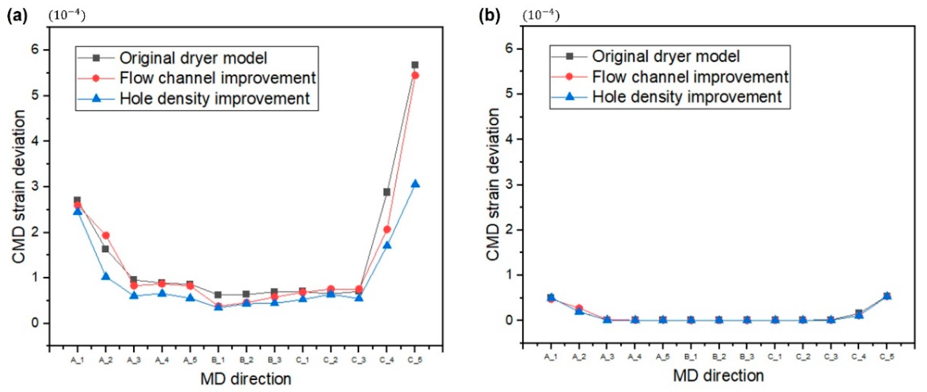
| PET Film | |||||||||||||||||
| Original Dryer Model | Flow Channel Improvement | Hole Density Improvement | |||||||||||||||
| MD | Std. Deviation [10−4] | MD | Std. Deviation [10−4] | MD | Std. Deviation [10−4] | MD | Std. Deviation [10−4] | MD | Std. Deviation [10−4] | MD | Std. Deviation [10−4] | MD | Std. Deviation [10−4] | MD | Std. Deviation [10−4] | MD | Std. Deviation [10−4] |
| A_1 | 2.7043 | B_1 | 0.6319 | C_1 | 0.7027 | A_1 | 2.5953 | B_1 | 0.3837 | C_1 | 0.6851 | A_1 | 2.4570 | B_1 | 0.3481 | C_1 | 0.5287 |
| A_2 | 1.6362 | B_2 | 0.6372 | C_2 | 0.6508 | A_2 | 1.9366 | B_2 | 0.4606 | C_2 | 0.7586 | A_2 | 1.0269 | B_2 | 0.4377 | C_2 | 0.6433 |
| A_3 | 0.9578 | B_3 | 0.6971 | C_3 | 0.7066 | A_3 | 0.8316 | B_3 | 0.5827 | C_3 | 0.7559 | A_3 | 0.6078 | B_3 | 0.4467 | C_3 | 0.5480 |
| A_4 | 0.8910 | C_4 | 2.8824 | A_4 | 0.8712 | C_4 | 2.0682 | A_4 | 0.6607 | C_4 | 1.7115 | ||||||
| A_5 | 0.8641 | C_5 | 5.6789 | A_5 | 0.8279 | C_5 | 5.4529 | A_5 | 0.5581 | C_5 | 3.0596 | ||||||
| PI Film | |||||||||||||||||
| Original Dryer Model | Flow Channel Improvement | Hole Density Improvement | |||||||||||||||
| MD | Std. Deviation [10−4] | MD | Std. Deviation [10−4] | MD | Std. Deviation [10−4] | MD | Std. Deviation [10−4] | MD | Std. Deviation [10−4] | MD | Std. Deviation [10−4] | MD | Std. Deviation [10−4] | MD | Std. Deviation [10−4] | MD | Std. Deviation [10−4] |
| A_1 | 0.5092 | B_1 | 0.0088 | C_1 | 0.0098 | A_1 | 0.4761 | B_1 | 0.0043 | C_1 | 0.0092 | A_1 | 0.5046 | B_1 | 0.0047 | C_1 | 0.0071 |
| A_2 | 0.1936 | B_2 | 0.0086 | C_2 | 0.0093 | A_2 | 0.2770 | B_2 | 0.0073 | C_2 | 0.0115 | A_2 | 0.1992 | B_2 | 0.0058 | C_2 | 0.0085 |
| A_3 | 0.0174 | B_3 | 0.0087 | C_3 | 0.0200 | A_3 | 0.0259 | B_3 | 0.0079 | C_3 | 0.0119 | A_3 | 0.0157 | B_3 | 0.0061 | C_3 | 0.0129 |
| A_4 | 0.0093 | C_4 | 0.1616 | A_4 | 0.0116 | C_4 | 0.1161 | A_4 | 0.0087 | C_4 | 0.1137 | ||||||
| A_5 | 0.0089 | C_5 | 0.5453 | A_5 | 0.0137 | C_5 | 0.5362 | A_5 | 0.0113 | C_5 | 0.5354 | ||||||
Publisher’s Note: MDPI stays neutral with regard to jurisdictional claims in published maps and institutional affiliations. |
© 2022 by the authors. Licensee MDPI, Basel, Switzerland. This article is an open access article distributed under the terms and conditions of the Creative Commons Attribution (CC BY) license (https://creativecommons.org/licenses/by/4.0/).
Share and Cite
Jo, M.; Noh, J.; Cho, G.; Lee, T.-m.; Oh, B.; Nam, S.; Lee, C. Strain Optimization of Tensioned Web through Computational Fluid Dynamics in the Roll-to-Roll Drying Process. Polymers 2022, 14, 2515. https://doi.org/10.3390/polym14122515
Jo M, Noh J, Cho G, Lee T-m, Oh B, Nam S, Lee C. Strain Optimization of Tensioned Web through Computational Fluid Dynamics in the Roll-to-Roll Drying Process. Polymers. 2022; 14(12):2515. https://doi.org/10.3390/polym14122515
Chicago/Turabian StyleJo, Minho, Jaehyun Noh, Gyoujin Cho, Taik-min Lee, Bukuk Oh, Sanghoon Nam, and Changwoo Lee. 2022. "Strain Optimization of Tensioned Web through Computational Fluid Dynamics in the Roll-to-Roll Drying Process" Polymers 14, no. 12: 2515. https://doi.org/10.3390/polym14122515