
Creep Behaviour of Recycled Poly(ethylene) Terephthalate Non-Woven Geotextiles

 , ,
, ,  and
and
Abstract
:
1. Introduction
2. Materials and Methods
2.1. Characteristics of the Geotextiles
2.2. Creep Test Program
3. Results
4. Discussion
5. Conclusions
- The investigated non-woven geotextiles showed creep strains with similar behaviour and order of magnitude compared to other geotextiles manufactured with virgin PET yarns/filaments. The variability of the non-woven geotextiles’ creep behavior tends to increase as the applied load level increases and also stems from the structural response of each sample (specimen) to the applied load level;
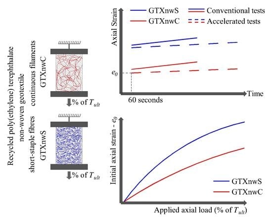
- Despite the existence of this variability, up to the limit of the conventional test period (1000 h or 3,600,000 s), the mean creep behaviour obtained from the accelerated creep tests show reasonable agreement compared to the mean creep behaviour obtained from the conventional test for the load levels higher than 5% of . However, GTXnwS exhibited a more accurate prediction with the accelerated creep tests than GTXnwC;
- The representation of a mean creep behaviour of the geotextiles using three and four specimens for conventional and accelerated creep tests, respectively, provides values of the coefficient of determination () higher than 0.90 for most load levels applied (regardless of the creep test type adopted). The mean regression line indicates that the accelerated creep test underestimates the creep strains of the geotextiles investigated since it provides lower values of the creep strain rate that the conventional tests;
- A non-linear increase in the initial axial strain values as the load level applied increase was reported for both geotextiles. The smallest variability in the initial axial strain occurred at the lower load level applied (5% of ). In this case, the load mobilises only a little of the structural elongation of the geotextile. For this lower load level, the creep strains developed are more governed by the specimen’s structural elongation than the filament/yarn (polymer) elongation. As the load level applied increases, the mobilised portion of the geotextile’s structural deformation increases and occurs in a shorter period, resulting in an increase in the initial axial strain; and
- The creep strains developed by GTXnwS are 50% higher (on average) than the creep strains developed by the GTXnwC. The lower creep modulus of the GTXnwS attached to the higher structural variability resulting from the manufacturing process is responsible for this significant difference in the geotextiles´ creep behaviour.
Author Contributions
Funding
Data Availability Statement
Acknowledgments
Conflicts of Interest
References
- Catsiff, E.; Alfrey, T.; O’Shaughnessy, M.T. Generalized creep curves for nylon. Text. Res. J. 1953, 23, 808–820. [Google Scholar] [CrossRef]
- Finnigan, J.A. The creep behaviour of high tenacity yarns and fabrics used in civil engineering applications. In Proceedings of the International Conference on the Use of Fabrics in Geotechnics, Paris, France, 20–22 April 1977; pp. 305–309. [Google Scholar]
- Gupta, V.B.; Sudarshana, G.R. Correlation between creep and dyeability of fibers. J. Appl. Polym. Sci. 1976, 20, 345–350. [Google Scholar] [CrossRef]
- Hadley, D.W.; Ward, I.M. Non-linear creep and recovery behaviour of polypropylene fibres. J. Mech. Phys. Solids 1965, 13, 397–411. [Google Scholar] [CrossRef]
- Morgan, C.J.; Ward, I.M. The temperature dependence of non-linear creep and recovery in oriented polypropylene. J. Mech. Phys. Solids 1971, 19, 165–178. [Google Scholar] [CrossRef]
- O’Shaughnessy, M.T. An experimental study of the creep of rayon. Text. Res. J. 1948, 18, 263–280. [Google Scholar] [CrossRef]
- Sherby, O.D.; Dorn, J.E. Anelastic creep of polymethyl methacrylate. J. Mech. Phys. Solids 1958, 6, 145–162. [Google Scholar] [CrossRef]
- Takaku, A. Effect of drawing on creep fracture of polypropylene fibers. J. Appl. Polym. Sci. 1981, 26, 3565–3573. [Google Scholar] [CrossRef]
- Wilding, M.; Ward, I. Tensile creep and recovery in ultra-high modulus linear polyethylenes. Polymer 1978, 19, 969–976. [Google Scholar] [CrossRef]
- ABNT (Brazilian Association of Technical Standards). NBR 15226: Geosynthetics—Determination of Tensile Creep and Creep Behavior; ABNT: Rio de Janeiro, Brazil, 2005; p. 14. [Google Scholar]
- BSI (British Standard Institute). BS EN ISO 13431:1999—Geotextiles and Geotextile-Related Products—Determination of Tensile Creep and Creep Rupture Behavior; British Standard Institute: London, UK, 1999; p. 16. [Google Scholar]
- ASTM (American Society for Testing and Materials). ASTM D 5262-07 Standard Test Method for Evaluating the Unconfined Tension Creep and Creep Rupture Behavior of Geosynthetics; ASTM: West Conshohocken, PA, USA, 2013; p. 16. [Google Scholar]
- Koo, H.-J.; Kim, Y.-K. Lifetime prediction of geogrids for reinforcement of embankments and slopes. Polym. Test. 2005, 24, 181–188. [Google Scholar] [CrossRef]
- Greenwood, J.H.; Voskamp, W. Predicting the long-term strength of a geogrid using the stepped isothermal method. In Proceedings of the 2nd European Geosynthetics Conference—EuroGEO II, Bologna, Italy, 15–18 October 2000; Soccodato, C., Cazzuffi, D., Cancelli, A., Eds.; Pàtron: Bologna, Italy, 2000; pp. 329–331. [Google Scholar]
- Jeon, H.Y.; Kim, S.H.; Yoo, H.K. Assessment of long-term performances of polyester geogrids by accelerated creep test. Polym. Test. 2002, 21, 489–495. [Google Scholar] [CrossRef]
- Viezee, D.J.; Voskamp, W.; den Hoedt, G.; Troost, G.H.; Schimidt, H.M. Designing soil reinforcement with woven geotextiles—The effect of mechanical damage and chemical ageing on the long-term performance of polyester fibres and fabrics. In Proceedings of the 4th International Conference on Geotextile, Geomembranes and Related Products, The Hauge, The Netherlands, 28 May–1 June 1990; Industrial Fabrics Association International: The Hauge, The Netherlands, 1990; pp. 651–656. [Google Scholar]
- McGown, A.; Praine, N.; Dubois, D.; Andrawes, K.Z.; Jewell, R.A. Use of geogrid properties in limit equilibrium analysis. In Polymer Grid Reinforcement; Thomas Telford Limited: London, UK, 1985; pp. 31–36. [Google Scholar]
- Matichard, Y.; Leclerq, B.; Segouinm, M. Creep of geotextiles: Soil reinforcement applications. In Proceedings of the 4th International Conference on Geotextile, Geomembranes and Related Products, The Hauge, The Netherlands, 28 May–1 June 1990; Industrial Fabrics Association International: The Hauge, The Netherlands, 1990; pp. 661–665. [Google Scholar]
- Andrawes, K.Z.; McGown, A.; Kabir, M.H. Uniaxial strength testing of woven and nonwoven geotextiles. Geotext. Geomembr. 1984, 1, 41–56. [Google Scholar] [CrossRef]
- Ashmawy, A.K.; Bourdeau, P.L. Response of a woven and a nonwoven geotextile to monotonic and cyclic simple tension. Geosynth. Int. 1996, 3, 493–515. [Google Scholar] [CrossRef]
- Coke, T.; Rebenfeld, L. Effect of chemical composition and physical structure of geotextiles on their durability. Geotext. Geomembr. 1988, 7, 7–22. [Google Scholar] [CrossRef]
- den Hoedt, G. Creep and relaxation of geotextile fabrics. Geotext. Geomembr. 1986, 4, 83–92. [Google Scholar] [CrossRef]
- Jewell, R.A.; Greenwood, J.H. Long term strength and safety in steep soil slopes reinforced by polymer materials. Geotext. Geomembr. 1988, 7, 81–118. [Google Scholar] [CrossRef]
- Koutsourais, M. Correlating the creep-strain component of the total strain as a function of load-level for high-tenacity polyester yarns, geogrids and geotextiles. In Geosynthetics ’95 Conference Proceedings; Industrial Fabrics Association International: Nashville, TN, USA, 1995; pp. 989–1001. [Google Scholar]
- Muller-Rochholz, J.; Alexiew, D.; Recker, C.; Lothspeich, S.E. Coated PET-geogrid, wovens and yarns—Comparision of longtime performance under tension. In Proceedings of the Sixth International Conference on Geosynthetics, Atlanta, GA, USA, 25–29 March 1998; Rowe, R.K., Ed.; Industrial Fabrics Association International: Atlanta, GA, USA, 1998; pp. 679–682. [Google Scholar]
- Shrestha, S.C.; Bell, J.R. Creep Behavior of Geotextiles under Sustained Loads. In Proceedings of the 2nd International Conference on Geotextiles—2nd ICG, Las Vegas, NV, USA, 1–6 August 1982; Industrial Fabrics Association International: Las Vegas, NV, USA, 1982; pp. 769–774. [Google Scholar]
- Wrigley, N.E. Durability and long-term performance of Tensar* polymer grids for soil reinforcement. Mater. Sci. Technol. 1987, 3, 161–170. [Google Scholar] [CrossRef]
- Baras, L.C.S.; Bueno, B.S.; Costa, C.M.L. On the evaluation of stepped isothermal method for characterizing creep properties of geotextiles. In Proceedings of the 7th International Conference on Geosynthetics—7th ICG, Nice, France, 22–27 September 2002; pp. 1515–1518. [Google Scholar]
- Blivet, J.C.; Msouti, M.; Matichard, Y.; Levacher, D. Mechanical behaviour of geotextiles in the design of pennanent reinforced structures. In Earth Reinforcement Pratice; Balkema: Fukuoka, Japan, 1992; pp. 35–38. [Google Scholar]
- Farrag, K.; Shirazi, H. Development of an Accelerated Creep Testing Procedure for Geosynthetics—Part I: Testing. Geotech. Test. J. 1997, 20, 414–422. [Google Scholar]
- Greenwood, J.H.; Myles, B. Creep and stress relaxation of geotextiles. In Proceedings of the 3rd international Conference on Geotextiles, Vienna, Austria, 7–11 April 1986; pp. 821–826. [Google Scholar]
- Hsuan, Y.G.; Yeo, S.-S. Comparing the Creep Behavior of High Density Polyethylene Geogrid Using Two Accereration Methods. In Slopes and Retaining Structures under Seismic and Static Conditions; GSP 140; American Society of Civil Engineers: Reston, VA, USA, 2005; pp. 2887–2901. [Google Scholar]
- Kaliakin, V.N.; Dechasakulsom, M.; Leshchinsky, D. Investigation of the isochrone concept for predicting relaxation of geogrids. Geosynth. Int. 2000, 7, 79–99. [Google Scholar] [CrossRef]
- Loginova, I.; Artamonova, D.; Stolyarov, O. Relationship between Structure and Viscoelastic Properties of Geosynthetics. MATEC Web Conf. 2016, 53, 01015. [Google Scholar] [CrossRef] [Green Version]
- Lothspeich, S.E.; Thornton, J.S. Comparison of different long term reduction factors for geosynthetic reinforcing materials. In Proceedings of the 2nd European Geosynthetics Congress—EuroGeo 2, Bologna, Italy, 15–18 October 2000; Soccodato, C., Cazzuffi, D., Cancelli, A., Eds.; Pàtron: Bologna, Italy, 2000; pp. 1–9. [Google Scholar]
- Srungeri, S.G.; Alekseev, N.N.; Kovalenko, I.A.; Stolyarov, O.N. Creep behavior of geosynthetics by temperature accelerated testing. Mag. Civ. Eng. 2017, 76, 255–265. [Google Scholar]
- Zornberg, J.G.; Byler, B.R.; Knudsen, J.W. Creep of Geotextiles Using Time–Temperature Superposition Methods. J. Geotech. Geoenviron. Eng. 2004, 130, 1158–1168. [Google Scholar] [CrossRef]
- Thornton, J.; Allen, S.R.; Thomas, R. Approaches for the prediction of long term viscoelastic properties of geosynthetics from short tem tests. In Geosynthetics ’97 Conference Proceedings; Industrial Fabrics Association International: Long Beach, CA, USA, 1997; pp. 278–291. [Google Scholar]
- Kabir, M.H. Creep behaviour of geotextiles. In Theory and Pratice of Earth Reinforcement; Mirua, N., Ochiai, H., Yamanouchi, T., Eds.; Balkema: Fukuoka, Japan, 1988; pp. 111–116. [Google Scholar]
- Wang, E.L.; Xu, E.L.; Zhang, B.; Zhong, H.; Gao, Z.K.; Chang, J.D. Experimental study on creep properties of plastic geogrid under low temperature. In Geosynthetics in Civil and Environmental Engineering: Proceedings of the 4th Asian Regional Conference Geosynthetics ASIA 2008 in Shanghai, China; Tang, G.L., Chen, Y., Tang, X., Eds.; Springer: Shangai, China, 2008; pp. 70–73. [Google Scholar]
- Wang, E.L.; Zhang, B.; Chang, J.D. Freeze-thaw cycle under the conditions of creep tests of plastics geogrid. Appl. Mech. Mater. 2012, 170–173, 317–321. [Google Scholar] [CrossRef]
- Yin, L. Experimental Research on geogrids Creep property of at different low temperatures. In Proceedings of the 6th International Conference on Measurement, Instrumentation, and Autimation—ICMIA 2017, Zhuhai, China, 29–30 June 2017; pp. 516–519. [Google Scholar]
- Zhang, Z. Experimental study on the Influence of temperature and confined load on the creep characteristics of geogrid. Adv. Mater. Res. 2014, 912–914, 1629–1632. [Google Scholar] [CrossRef]
- Bush, D.I. Variation of long term design strength of geosynthetics in temperatures up to 40 °C. In Proceedings of the 4th International Conference on Geotextile, Geomembranes and Related Products, The Hauge, The Netherlands, 28 May–1 June 1990; Industrial Fabrics Association International: The Hauge, The Netherlands, 1990; pp. 673–676. [Google Scholar]
- Chantachot, T.; Kongkitkul, W.; Tatsuoka, F. Load-strain-time behaviours of two polymer geogrids affected by temperature. Int. J. Geomate 2016, 10, 1869–1876. [Google Scholar]
- Chantachot, T.; Kongkitkul, W.; Tatsuoka, F. Effects of temperature on elastic stiffness of a HDPE geogrid and its model simulation. Int. J. Geomate 2017, 12, 94–100. [Google Scholar]
- Chantachot, T.; Kongkitkul, W.; Tatsuoka, F. Effects of temperature rise on load-strain-time behaviour of geogrids and simulations. Geosynth. Int. 2018, 25, 287–303. [Google Scholar] [CrossRef]
- Farrag, K. Development of an accelerated creep testing procedure for geosynthetics, Part II: Analysis. Geotech. Test. J. 1998, 21, 38–44. [Google Scholar]
- Helwany, B.; Wu, J.T.H. A generalized creep model for geosynthetics. In Earth Reinforcement Pratice; Balkema: Fukuoka, Japan, 1992; pp. 79–84. [Google Scholar]
- Hsieh, C.; Chuang, B.F.; Tseng, Y.C. Tensile creep behavior of a PVC coated polyester geogrid at different temperatures. In Proceedings of the 9th International Conference on Geosynthetics—ICG 2010, Guarujá, Brazil, 23–27 May 2010; pp. 855–860. [Google Scholar]
- Tong, J.; Gong, B.; Liu, J. Experimental study and prediction on the long-term creep properties for geogrids at different temperatures. In Proceedings of the 9th International Conference on Geosynthetics—9th ICG, Guarujá, São Paulo, Brazil, 23–27 May 2010; Palmeira, E.M., Ed.; Brazilian Chapter of the International Geosynthetics Society: Guarujá, São Paulo, Brazil, 2010; pp. 873–876. [Google Scholar]
- Allen, T.; Vinson, T.S.; Bell, J.R. Tensile Strength and Creep Behavior of Geotextiles in Cold Regions Applications. In Proceedings of the 2nd International Conference on Geotextiles, Las Vegas, NV, USA, 1–6 August 1982; pp. 775–780. [Google Scholar]
- Popelar, C.H.; Kenner, V.H.; Wooster, J.P. An accelerated method for establishing the long term performance of polyethylene gas pipe materials. Polym. Eng. Sci. 1991, 31, 1693–1700. [Google Scholar] [CrossRef]
- Thornton, J.S.; Paulson, J.N.; Sandri, D. Conventional and stepped isothermal methods for characterizing long term creep strength of polyester geogrids. In Proceedings of the Sixth International Conference on Geosynthetics, Atlanta, GA, USA, 25–29 March 1998; Rowe, R.K., Ed.; Industrial Fabrics Association International: Atlanta, GA, USA, 1998; pp. 691–698. [Google Scholar]
- Greenwood, J.H.; Kempton, G.T.; Watts, G.R.A.; Bush, D.I. Twelve year creep tests on geosynthetic reinforcements. In Proceedings of the 2nd European Geosynthetics Congress—EuroGeo II, Bologna, Italy, 15–18 October 2000; Soccodato, C., Cazzuffi, D., Cancelli, A., Eds.; Pàtron: Bologna, Italy, 2000; pp. 333–336. [Google Scholar]
- Allen, T.M.; Bathurst, R.J. Combined Allowable Strength Reduction Factor for Geosynthetic Creep and Installation Damage. Geosynth. Int. 1996, 3, 407–439. [Google Scholar] [CrossRef]
- Bhuvanesh, Y.C.; Gupta, V.B. Long-term prediction of creep in textile fibres. Polymer 1994, 35, 2226–2228. [Google Scholar] [CrossRef]
- Farrag, K. Prediction of long-term strains of geosynthetics from accelerated-creep test. In Proceedings of the Geosynthetics’ 97 Conference, Long Beach, CA, USA, 11–13 March 1997; pp. 267–276. [Google Scholar]
- Fan, C.; Xiang, Q.; Liu, H. Influence of long-term stiffness of geogrids on the reinforcement load of reinforced retaining walls. In Proceedings of the Eighth International Conference on Case Histories in Geotechnical Engineering—Geo-Congress 2019, Philadelphia, PA, USA, 24–27 March 2019; American Society of Civil Engineers: Philadelphia, PA, USA, 2019; pp. 354–363. [Google Scholar]
- Jeon, H.-Y.; Mok, M.-S.; Kim, Y.-K. Analysis of creep behaviors of geosynthetic reinforcements by newly designed test method. In Proceedings of the 3rd European Geosynthetics Congress—EuroGeo III, Munich, Germany, 1–4 March 2004; pp. 697–700. [Google Scholar]
- Thornton, J.S.; Baker, T.L. Comparison of SIM and conventional methods for determining creep-rupture behavior of a polypropylene geotextile. In Proceedings of the 7th International Conference on Geosynthetics—7th ICG, Nice, France, 22–27 September 2002; pp. 1545–1550. [Google Scholar]
- Wang, Q.; Wen, X.; Jiang, J.; Zhang, C.; Shi, Z. Experimental study on performance of multidirectional geogrid and its application in engineering of high slope. J. Wuhan Univ. Technol. Sci. Ed. 2014, 29, 704–711. [Google Scholar] [CrossRef]
- Williams, M.L.; Landel, R.F.; Ferry, J.D. The Temperature Dependence of Relaxation Mechanisms in Amorphous Polymers and Other Glass-forming Liquids. J. Am. Chem. Soc. 1955, 77, 3701–3707. [Google Scholar] [CrossRef]
- Costanzi, M.A.; Bueno, B.S. Accelerated creep tests on nonwoven geotextiles with SIM. In Proceedings of the 4th Brazilian Conference on Geosynthetics, Porto Alegre, Rio Grande do Sul, Brazil, 14–16 August 2003; p. 8. [Google Scholar]
- Yeo, S.-S.; Hsuan, Y.G. Predicting the Creep Behavior of High Density Polyethylene Geogrid Using Stepped Isothermal Method. In Service Life Prediction of Polymeric Materials; Springer: Boston, MA, USA, 2009; pp. 205–218. [Google Scholar]
- Yeo, S.S.; Hsuan, Y.G. Evaluation of creep behavior of high density polyethylene and polyethylene-terephthalate geogrids. Geotext. Geomembr. 2010, 28, 409–421. [Google Scholar] [CrossRef]
- Thornton, J.S.; Allen, S.R.; Thomas, R.W.; Sandri, D. The stepped isothermal method for time-temperature superposition and its application to creep data on polyester yarn. In Proceedings of the Sixth International Conference on Geosynthetics, Atlanta, GA, USA, 25–29 March 1998; Rowe, R.K., Ed.; Industrial Fabrics Association International: Atlanta, GA, USA, 1998; pp. 699–706. [Google Scholar]
- Bueno, B.S.; Costanzi, M.A.; Zornberg, J.G. Conventional and accelerated creep tests on nonwoven needle-punched geotextiles. Geosynth. Int. 2005, 12, 276–287. [Google Scholar] [CrossRef]
- ASTM (American Society for Testing and Materials). ASTM D 6992-16: Accelerated Tensile Creep and Creep-Rupture of Geosynthetic Materials Based on Time-Temperature Superposition Using the Stepped Isothermal Method; ASTM: West Conshohocken, PA, USA, 2016; p. 15. [Google Scholar]
- ISO (International Organization for Standardization). Guidelines for the Determination of the Long-Term Strength of Geosynthetics for Soil Reinforcement; ISO TR 20432:2007; ISO: Geneva, Switzerland, 2007. [Google Scholar]
- Bueno, B.S. Long-term performance of geosynthetics. In Proceedings of the 9th International Conference on Geosynthetics—9th ICG, Guarujá, São Paulo, Brazil, 23–27 May 2010; pp. 439–453. [Google Scholar]
- Thomas, R.W.; Nelson, J.A. The stepped isothermal method for estimating the long-term creep strain and creep rupture strength of polypropylene resins used in civil engineering applications. In Proceedings of the 2013 Society of Plastics Engineers (SPE) International Polyolefins Conference, Houston, TX, USA, 24–27 February 2013. [Google Scholar]
- ABNT (Brazilian Association of Technical Standards). NBR 16757-1: Geosynthetics—Application Requirements: Part I—Geotextiles and Geotextiles Related Products; Associação Brasileira de Normas Técnicas (ABNT): Rio de Janeiro, Brazil, 2020; p. 13. [Google Scholar]
- Haliburton, T.A.; Anglin, C.C.; Lawmaster, J.D. Testing of Geotechnical Fabric for Use as Reinforcement. Geotech. Test. J. 1978, 1, 203–212. [Google Scholar]
- Fourie, A.B.; Kuchena, S.M. The influence of tensile stresses on the filtration characteristics of geotextiles. Geosynth. Int. 1995, 2, 455–471. [Google Scholar] [CrossRef]
- ABNT (Brazilian Association of Technical Standards). NBR ISO 12236: Criteria of Project, Building and Operation of Compressed Fuel Gas Filling Station—Procedure; ABNT: Rio de Janeiro, Brazil, 2013; p. 7. [Google Scholar]
- ABNT (Brazilian Association of Technical Standards). NBR ISO 9864: Geosynthetics—Test Method for the Determination of Mass Per Unit Area of Geotextiles and Geotextile-Related Products; ABNT: Rio de Janeiro, Brazil, 2013; p. 2. [Google Scholar]
- ASTM (American Society for Testing and Materials). ASTM D 4833-07: Standard Test Method for Index Puncture Resistence of Geomembranes and Related Products; ASTM: West Conshohocken, PA, USA, 2009; p. 4. [Google Scholar]
- ASTM (American Society for Testing and Materials). ASTM D 4632-08: Standard Test Method for Grab Breaking Load and Elongation of Geotextiles; ASTM: West Conshohocken, PA, USA, 2008; p. 4. [Google Scholar]
- ASTM (American Society for Testing and Materials). ASTM D 4595-09 Standard Test Method for Tensile Properties of Geotextiles by the Wide-Width Strip Method; ASTM: West Conshohocken, PA, USA, 2009; p. 12. [Google Scholar]
- ASTM (American Society for Testing and Materials). ASTM D 4533-04: Standard Test Method for Tapezoid Tearing Strength of Geotextiles; ASTM: West Conshohocken, PA, USA, 2004; p. 4. [Google Scholar]
- Bueno, B.S. The Behavior of Thin Walled Pipes in Trenches; University of Leeds: Leeds, UK, 1987. [Google Scholar]
- França, F.A.N.; Massimino, B.M.; Silva, J.O.; Iceri, F.Y.; Zornberg, J.G. Geogrid creep and tensile tests performed with nonconventional equipment. In Proceedings of the 10th International Conference on Geosynthetics—10th ICG, Berlim, Germany, 21–25 September 2014; The Federation of International Geo-Engineering Societies: Berlim, Germany, 2014; p. 6. [Google Scholar]
- Miki, H.; Hayashi, Y.; Yamada, K.; Takasago, T.; Shido, H. Plane strain tensile strength and creep of spun-bonded non-wovens. In Proceedings of the 4th International Conference on Geotextile, Geomembranes and Related Products, The Hauge, The Netherlands, 28 May–1 June 1990; pp. 667–672. [Google Scholar]
- Greenwood, J.H. The creep of geotextiles. In Proceedings of the 4th International Conference on Geotextile, Geomembranes and Related Products, The Hauge, The Netherlands, 28 May–1 June 1990; Den Hoedt, G., Ed.; Balkema: The Hauge, The Netherlands, 1990; pp. 645–650. [Google Scholar]
- El-Shabrawy, M.; Al-Mudhaf, H. Performance and creep characteristics of synthetic geogrids following hot dry climate. In International Symposium on Earth Reinforcement; Ochiai, H., Yasufuku, N., Omine, K., Kogakkai, J., Eds.; Balkema (Taylor & Francis Group): Fukuoka, Japan, 1996; pp. 29–33. [Google Scholar]
- Leshchinsky, D.; Dechasakulsom, M.; Kaliakin, V.N.; Ling, H.I. Creep and Stress Relaxation of Geogrids. Geosynth. Int. 1997, 4, 463–479. [Google Scholar] [CrossRef]


| Parameters | Testing Standard | Specimens Tested | GTXnwC 1 | GTXnwS 2 |
|---|---|---|---|---|
| Mass per unit area (g/m2) | NBR ISO 9864 [77] | 10 | 269 (9.34) | 384 (12.48) |
| Thickness (mm) | NBR ISO 9864 [77] | 10 | 2.51 (11.53) | 2.91 (9.23) |
| Static puncture strength (kN) | NBR ISO 12236 [76] | 5 | 2.80 (9.16) | 2.35 (16.38) |
| Dynamic puncture strength (kN) | ASTM D 4833-07 [78] | 15 | 0.53 (9.65) | 0.50 (18.99) |
| Trapezoid tearing strength MD 3 (kN) | ASTM D 4533-04 [81] | 10 | 0.44 (16.55) | 0.48 (13.98) |
| Trapezoid tearing strength CMD 4 (kN) | ASTM D 4533-04 [81] | 10 | 0.46 (22.44) | 0.38 (26.47) |
| Grab tensile strength MD 3 (kN) | ASTM D 4632-08 [79] | 10 | 0.97 (15.36) | 0.78 (17.01) |
| Grab tensile strength CMD 4 (kN) | ASTM D 4632-08 [79] | 10 | 0.93 (14.02) | 0.85 (15.84) |
| Grab breaking elongation MD 3 (%) | ASTM D 4632-08 [79] | 10 | 71.32 (10.40) | 87.65 (7.36) |
| Grab breaking elongation CMD 4 (%) | ASTM D 4632-08 [79] | 10 | 77.27 (5.22) | 92.47 (10.38) |
| Wide-width tensile strength MD 3 (kN/m) | ASTM D 4595-05 [80] | 10 | 14.91 (11.35) | 12.60 (14.56) |
| Elongation at failure MD 3 (%) | ASTM D 4595-05 [80] | 10 | 48.61 (21.82) | 60.1 (9.66) |
| Geotextile | Creep Test Type | (%/mm) | Parameter “b” (%) | ||
|---|---|---|---|---|---|
| GTXnwC 3 | 5 | Conventional | 0.6081 | 0.7255 | 0.9966 |
| SIM 5 | 0.1307 | 2.4373 | 0.9952 | ||
| 10 | Conventional | 0.5913 | 5.3433 | 0.9823 | |
| SIM 5 | 0.3150 | 5.6037 | 0.9774 | ||
| 20 | Conventional | 0.8550 | 12.1600 | 0.9891 | |
| SIM 5 | 0.2762 | 11.2789 | 0.9730 | ||
| 40 | Conventional | 1.1104 | 21.2497 | 0.9985 | |
| SIM 5 | 0.3826 | 19.9180 | 0.9370 | ||
| 60 | Conventional | 1.3854 | 31.0211 | 0.9972 | |
| SIM 5 | 0.5526 | 29.6414 | 0.9816 | ||
| GTXnwS 4 | 5 | Conventional | 0.2918 | 4.1916 | 0.9871 |
| SIM 5 | 0.2331 | 5.6368 | 0.9813 | ||
| 10 | Conventional | 0.3343 | 12.9576 | 0.9518 | |
| SIM 5 | 0.4249 | 13.6262 | 0.8022 | ||
| 20 | Conventional | 0.6908 | 22.2668 | 0.9858 | |
| SIM 5 | 0.3241 | 21.6069 | 0.8888 | ||
| 40 | Conventional | 1.0993 | 42.5398 | 0.9976 | |
| SIM 5 | 0.4720 | 39.7159 | 0.9557 | ||
| 60 | Conventional | 1.4185 | 52.3469 | 0.9981 | |
| SIM 5 | 0.5119 | 52.8446 | 0.8961 |
Publisher’s Note: MDPI stays neutral with regard to jurisdictional claims in published maps and institutional affiliations. |
© 2021 by the authors. Licensee MDPI, Basel, Switzerland. This article is an open access article distributed under the terms and conditions of the Creative Commons Attribution (CC BY) license (http://creativecommons.org/licenses/by/4.0/).
Share and Cite
Fleury, M.P.; Nascimento, L.D.d.; Valentin, C.A.; Lins da Silva, J.; Luz, M.P.d. Creep Behaviour of Recycled Poly(ethylene) Terephthalate Non-Woven Geotextiles. Polymers 2021, 13, 752. https://doi.org/10.3390/polym13050752
Fleury MP, Nascimento LDd, Valentin CA, Lins da Silva J, Luz MPd. Creep Behaviour of Recycled Poly(ethylene) Terephthalate Non-Woven Geotextiles. Polymers. 2021; 13(5):752. https://doi.org/10.3390/polym13050752
Chicago/Turabian StyleFleury, Mateus Porto, Lucas Deroide do Nascimento, Clever Aparecido Valentin, Jefferson Lins da Silva, and Marta Pereira da Luz. 2021. "Creep Behaviour of Recycled Poly(ethylene) Terephthalate Non-Woven Geotextiles" Polymers 13, no. 5: 752. https://doi.org/10.3390/polym13050752