
Manufacturing Technologies of Carbon/Glass Fiber-Reinforced Polymer Composites and Their Properties: A Review


Abstract
:
1. Introduction
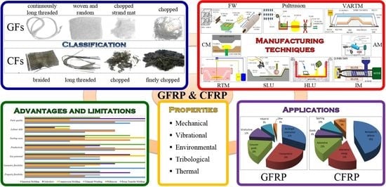
2. Glass Fibers and Carbon Fibers
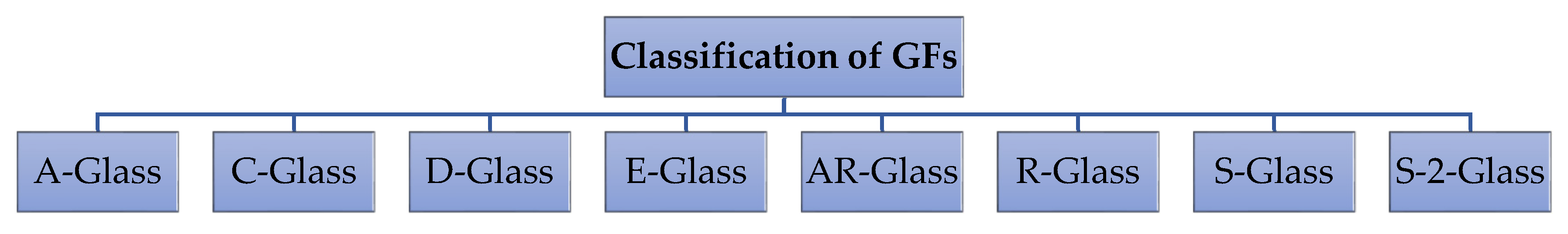
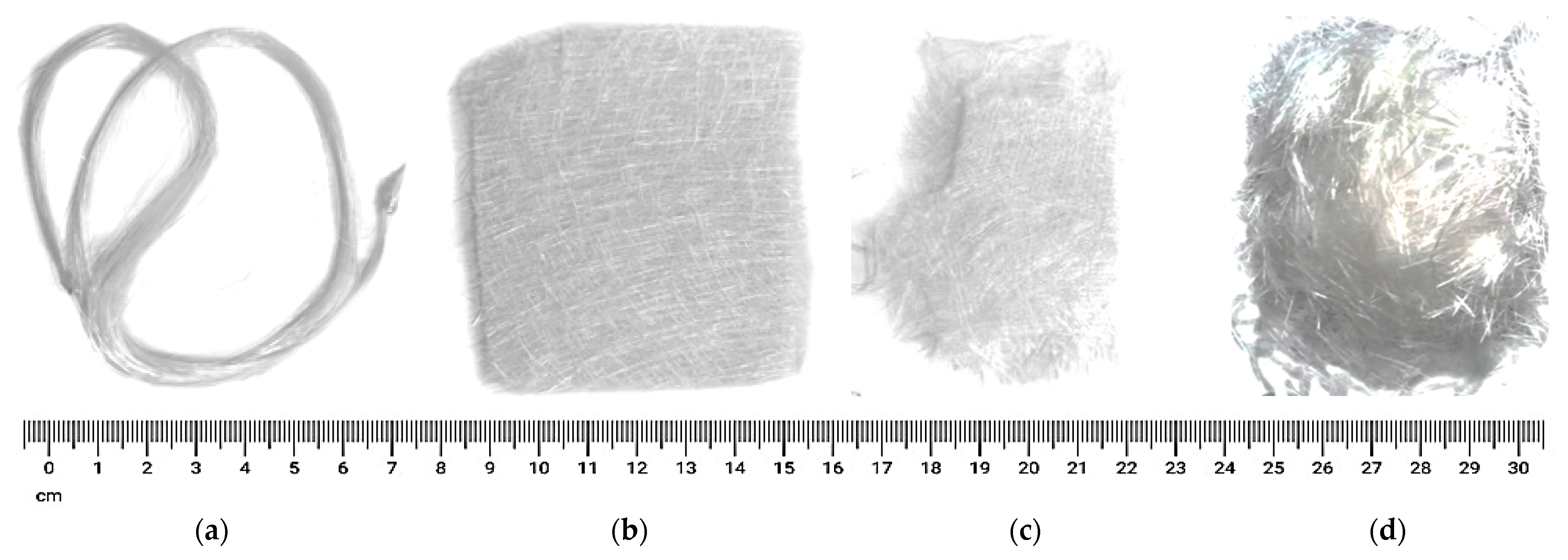
2.1. Glass Fibers
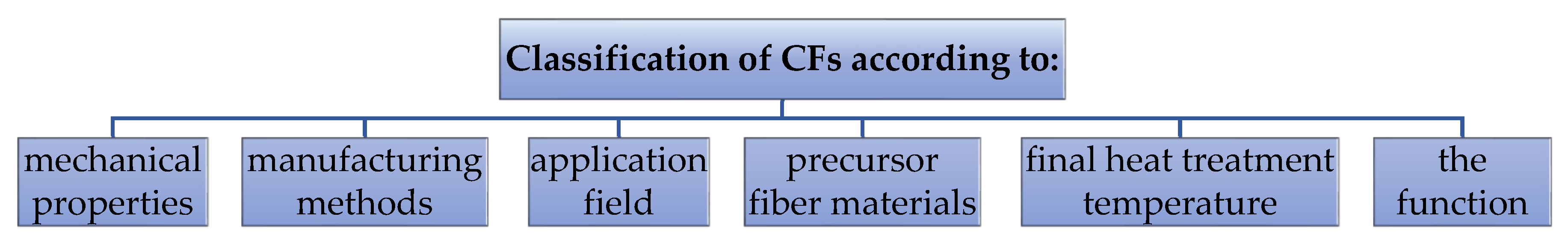
2.2. Carbon Fibers
- (a)
- Based on the type of precursor fiber materials: pitch-based CFs, PAN-based CFs, mesophase pitch-based CFs, rayon-based CFs: obtained by pyrolysis to form the first high-strength CF, isotropic pitch-based CFs and gas-phase-grown CFs.
- (b)
- Based on mechanical properties of CFs: general-grade CFs, and high-performance CFs, that include middle, high (>3.0 GPa) and ultra-high (>4.5 GPa) tensile strength type, and low (<100 GPa), intermediate (200–350 GPa), high (350–450 GPa) and ultra-high (>450 GPa) modulus type.
- (c)
- Based on final heat treatment temperature (FHTT): Class-I, high-heat-treatment CFs, where FHTT > 2000 °C, being correlated with high-modulus CFs; Class-II, intermediate-heat-treatment CFs, where FHTT ≥ 1500 °C, being correlated with high-strength CFs; Class-III, low-heat-treatment CFs, where FHTT < 1000 °C, being correlated with low-modulus and low-strength CFs.
- (d)
- Based on different manufacturing methods: carbon fiber (800–1600 °C), oxidative fibers (peroxidation fiber at 200–300 °C), graphite fibers (2000–3000 °C), activated CF and vapor-grown CF.
- (e)
- Based on the function: flame-resistant CFs, load structure using CFs, activated CFs (adsorption activity), CFs used for lubrication, conductive CFs, corrosion-resistant CFs and wear-resistant CFs.
- (f)
- Based on the application field: Commercial-grade CFs: have a large tow, and are associated with a cluster of monofilament thread of more than 24 K (1 K = 1000). To lessen the cost, large-tow fibers of 360 K, 480 K and 540 K were adopted. Aerospace-grade CFs, with a short tow (<12 K), and higher, of 1 K and 3 K carbon fiber tow, recently developed to 6 K and 12 K.
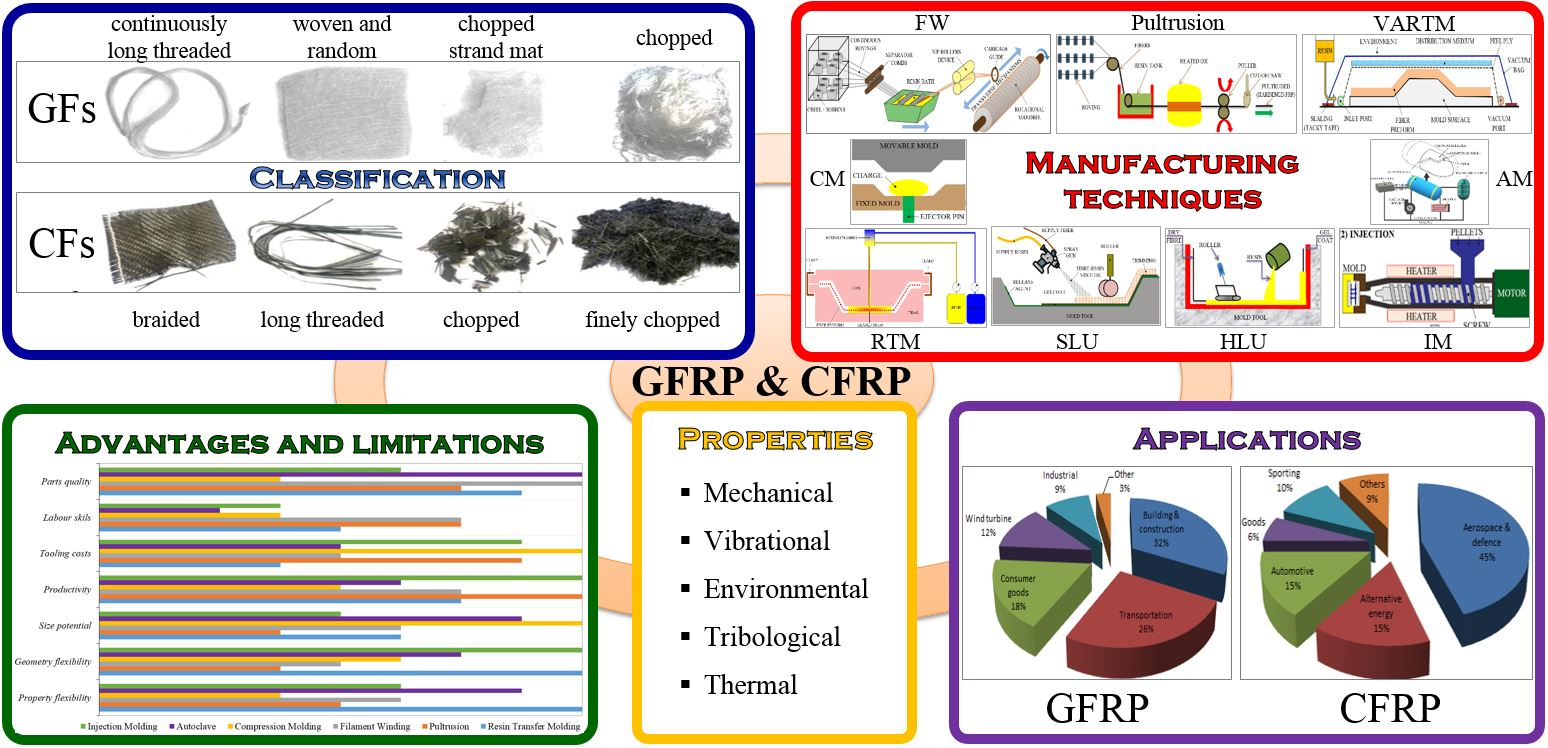
3. Manufacturing Methodologies of GFRP and CFRP Composites
3.1. Matched Die Molding
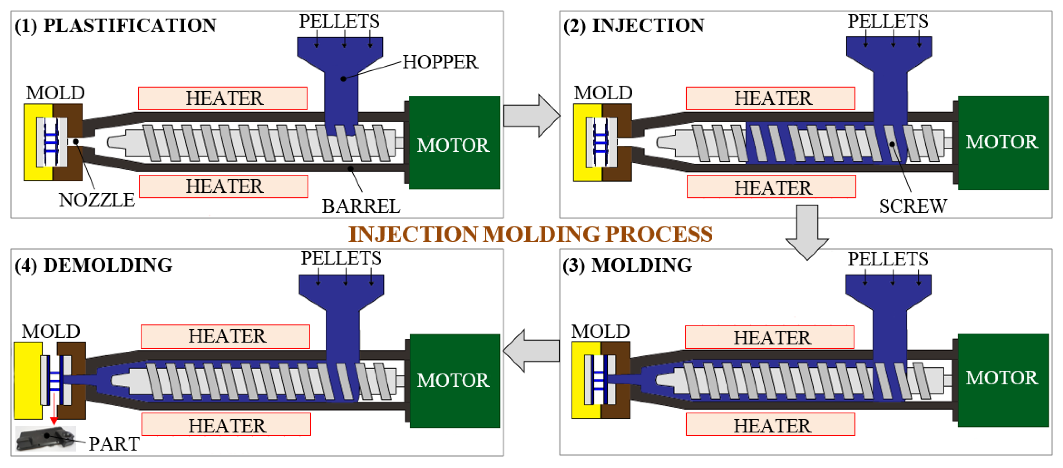
3.1.1. Injection Molding Process
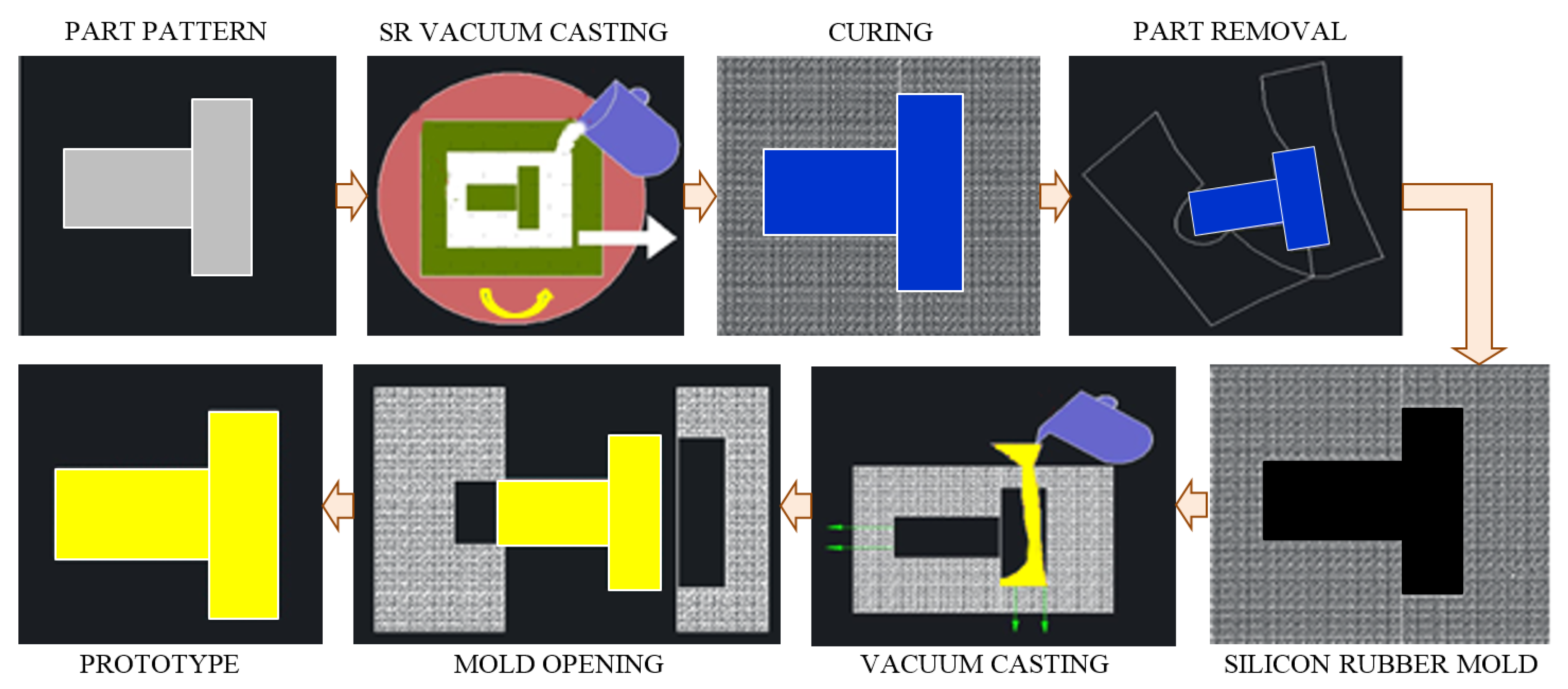
3.1.2. Silicone Rubber Mold Process
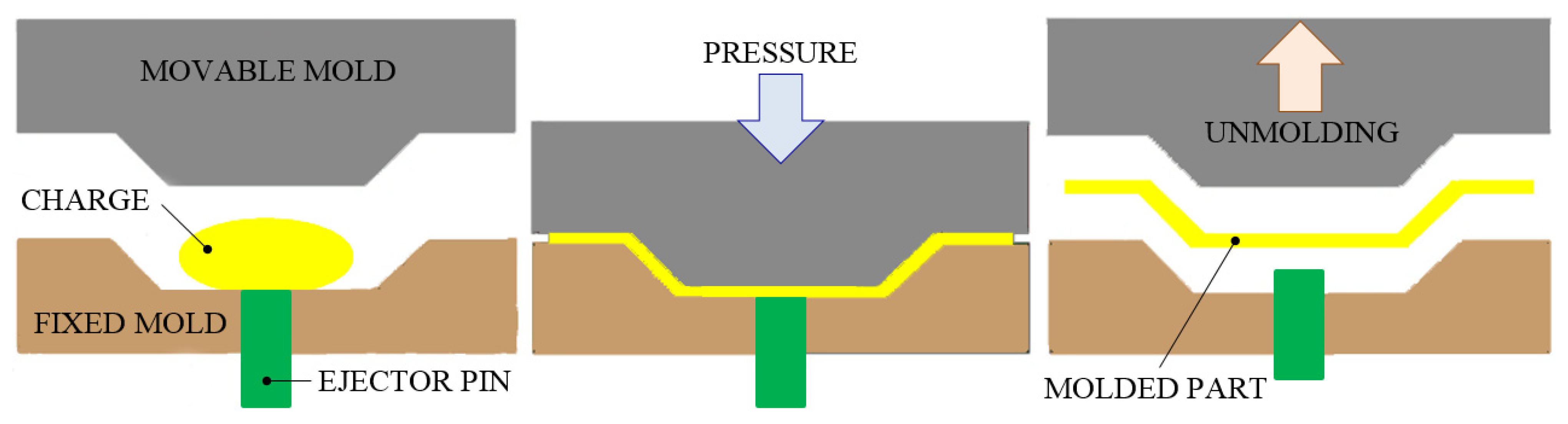
3.1.3. Compression Molding Process
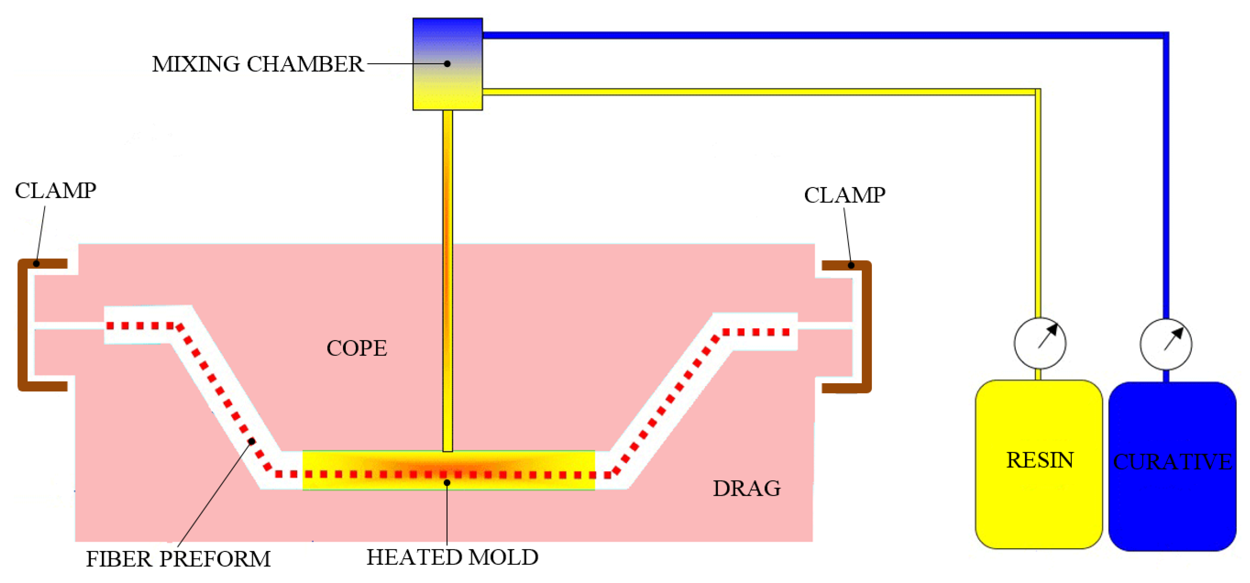
3.1.4. Resin Transfer Molding Process
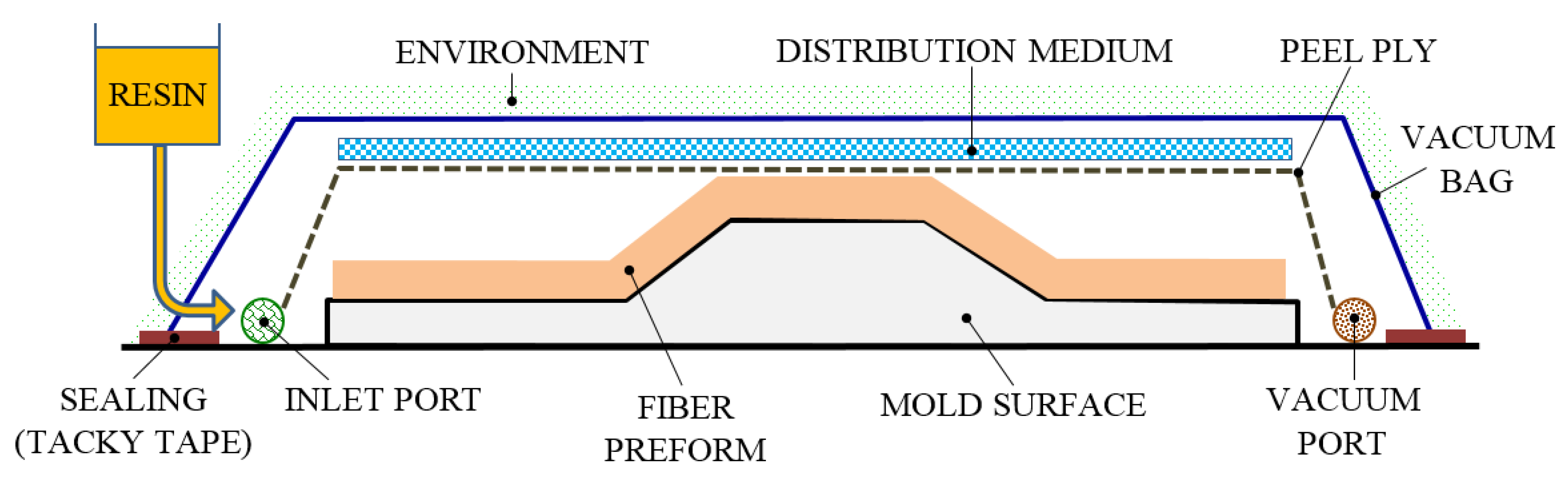
3.1.5. Vacuum-Assisted Resin Transfer Molding Process
3.2. Matched Die Molding
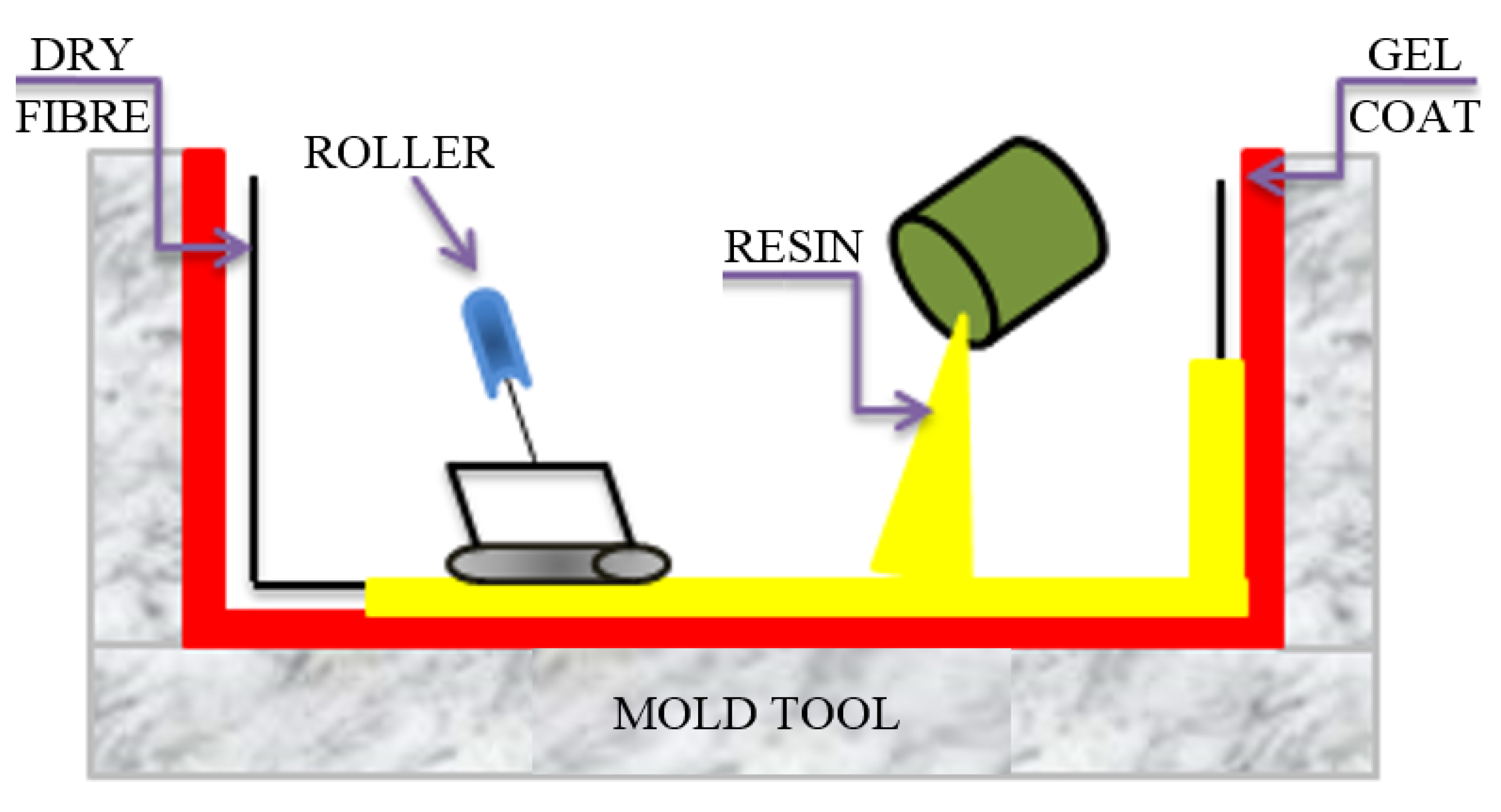
3.2.1. Dry Hand Lay-Up Process
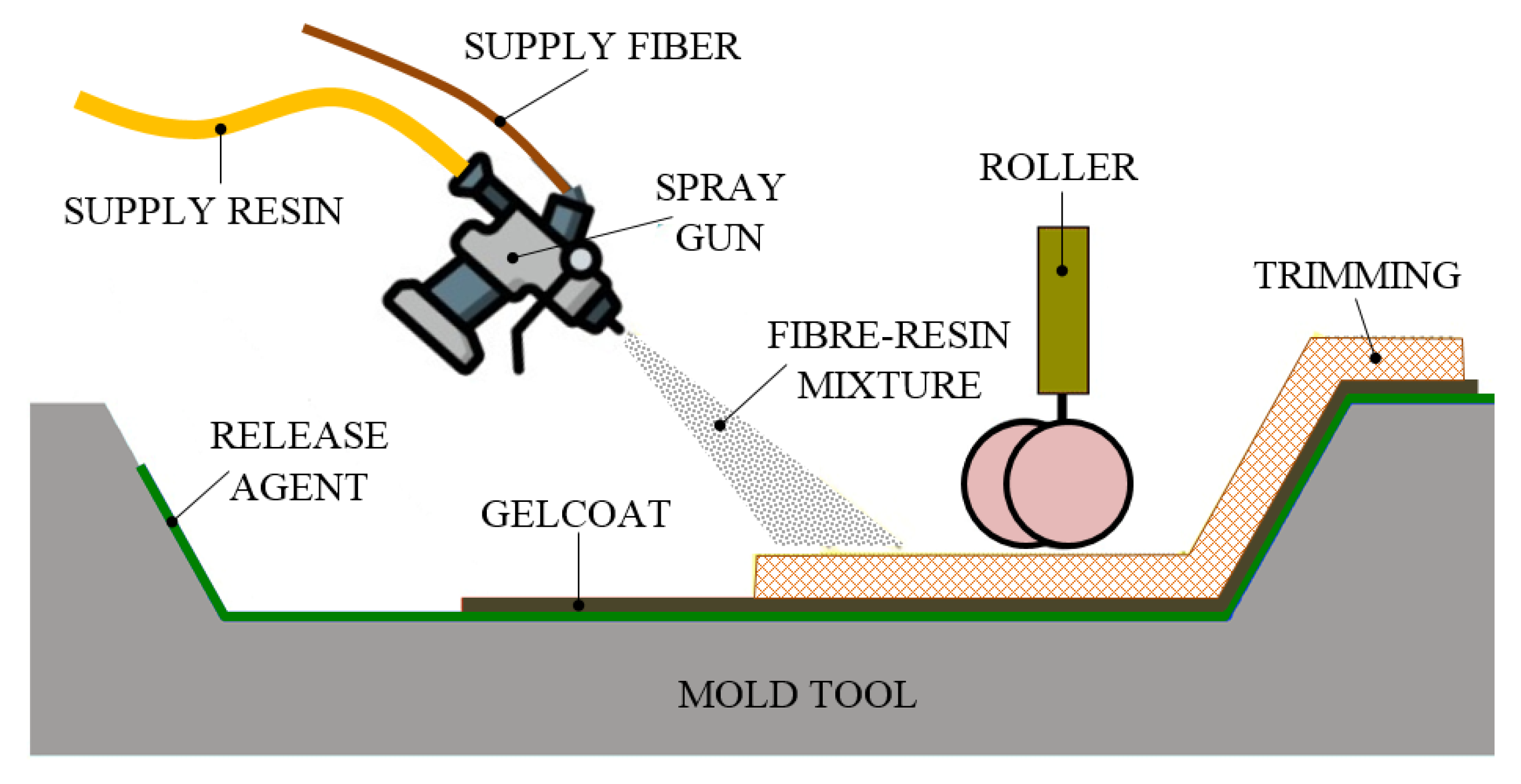
3.2.2. Spray Lay-Up Process
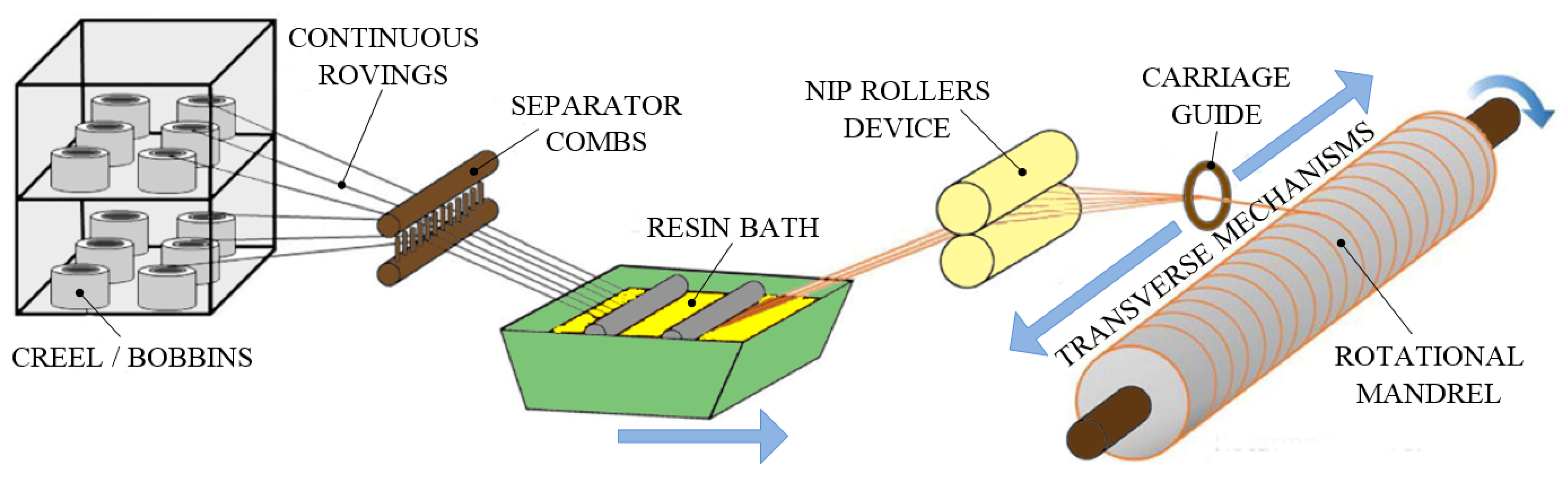
3.2.3. Filament Winding Process
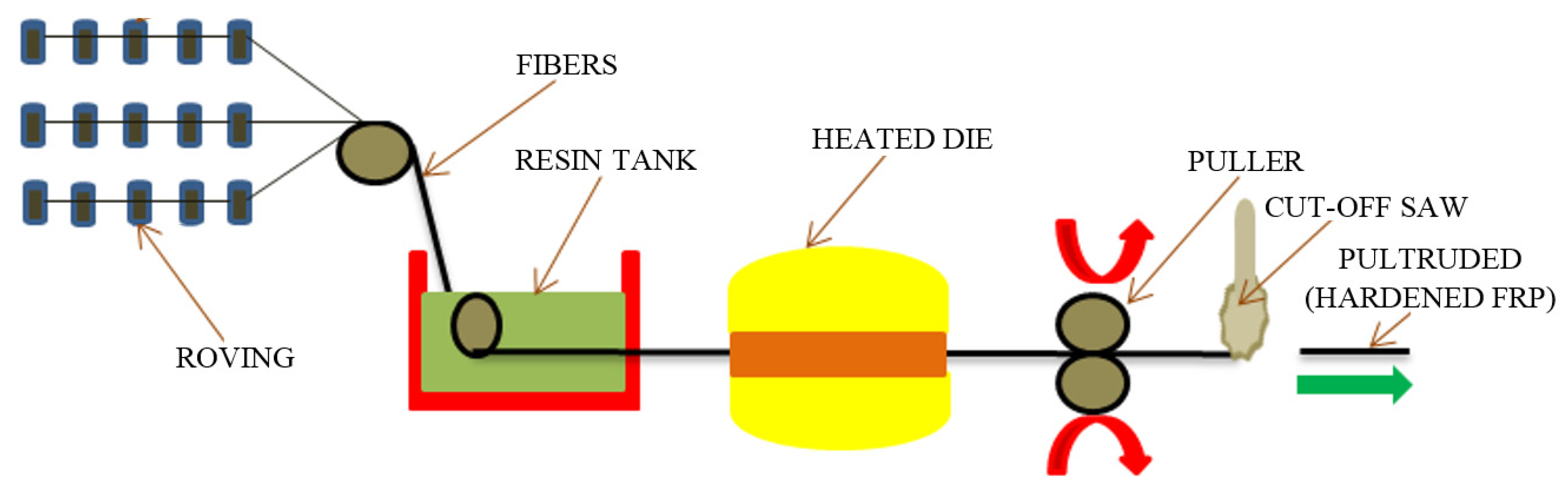
3.2.4. Pultrusion Process
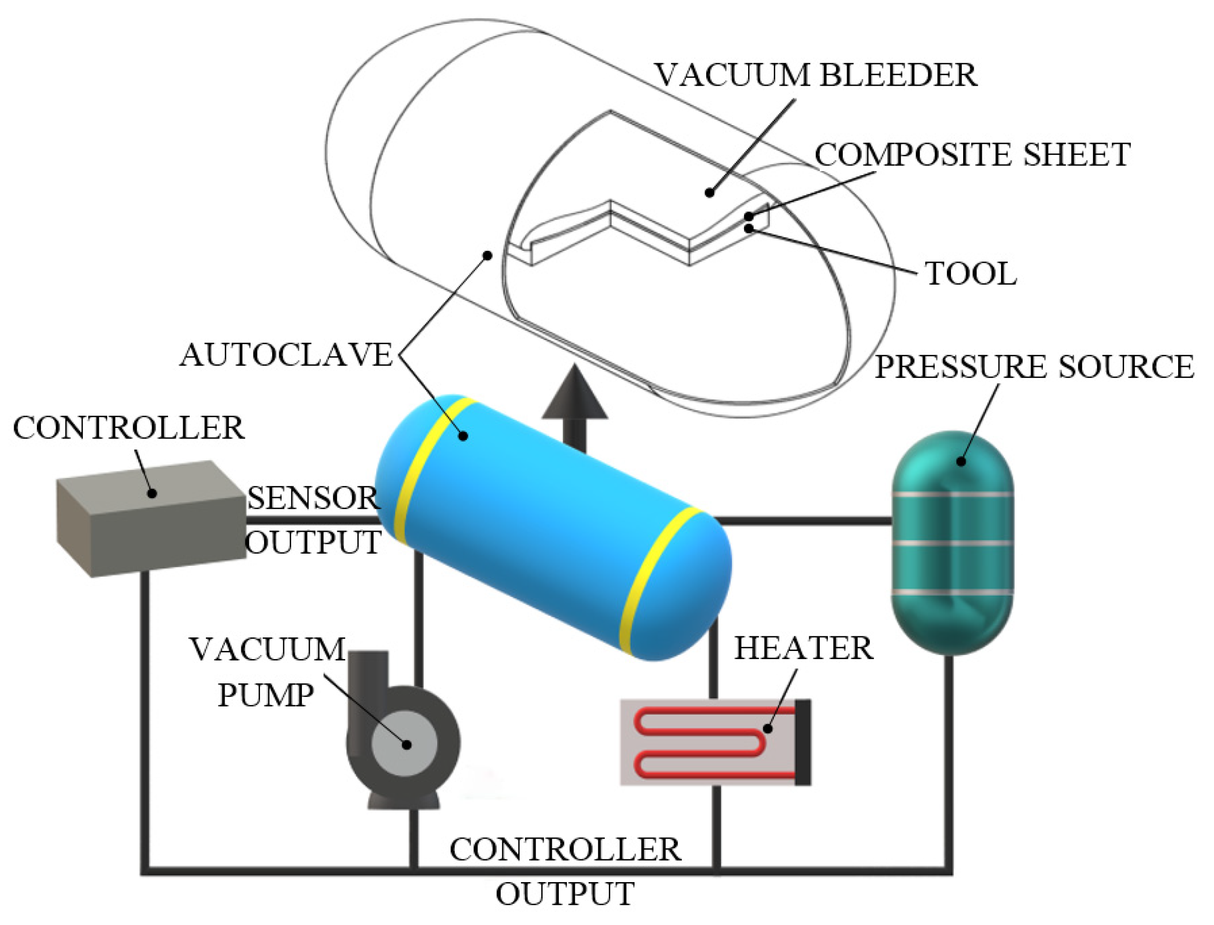
3.2.5. Autoclave Molding Process
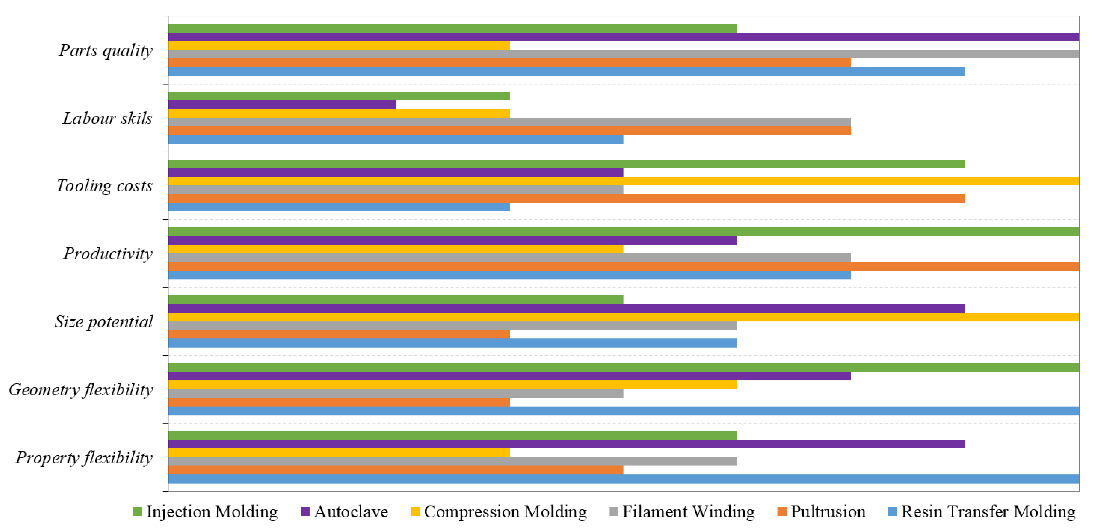
3.3. Advantages and Limitations of FRP Manufacturing Methodologies
4. Properties of GFRP and CFRP Composites
4.1. Mechanical Properties

| Reference | Type of CF | Resin | Curing Agent | Testing Standard | Fiber Volume Fraction (%) | Process Type | Sample Thickness (mm) | Tensile Strength (MPa) | Flexural Strength (MPa) | Elongation at Break (%) |
|---|---|---|---|---|---|---|---|---|---|---|
| [114] | PAN- based carbon fiber | Polyamide6 and polyphenylene sulphide | - | - | - | Injection molding | 2 | 70 | - | - |
| [115] | Polyacrylonitrile | - | GB/T1040–1992 | - | Hand lay-up | 5 | 135 | - | - | |
| [116] | Polyphenylene sulfide/Polytetrafluoroethylene | Standard–GB 3960-83 | - | Mixing and molding | 4 | 113 | - | - | ||
| [117] | Epoxy | Hardner | - | 40 | Mixing method | 2 | 3720 | - | 1.6 | |
| [118] | Epoxy | Hardner | ISO 178-1993 | - | - | - | - | 1154 | - | |
| [119] | Epoxy | Hardner | ASTM D-2344 | 15 | Drum winding | 0.5 | 277 | - | ||
| [120] | Epoxy/phenoxy | Hardner | ISO 180/1A | - | Extrusion | 4 | - | - | - |
4.2. Vibration Properties
4.3. Environmental Properties
4.4. Tribological Properties
4.5. Thermal Properties
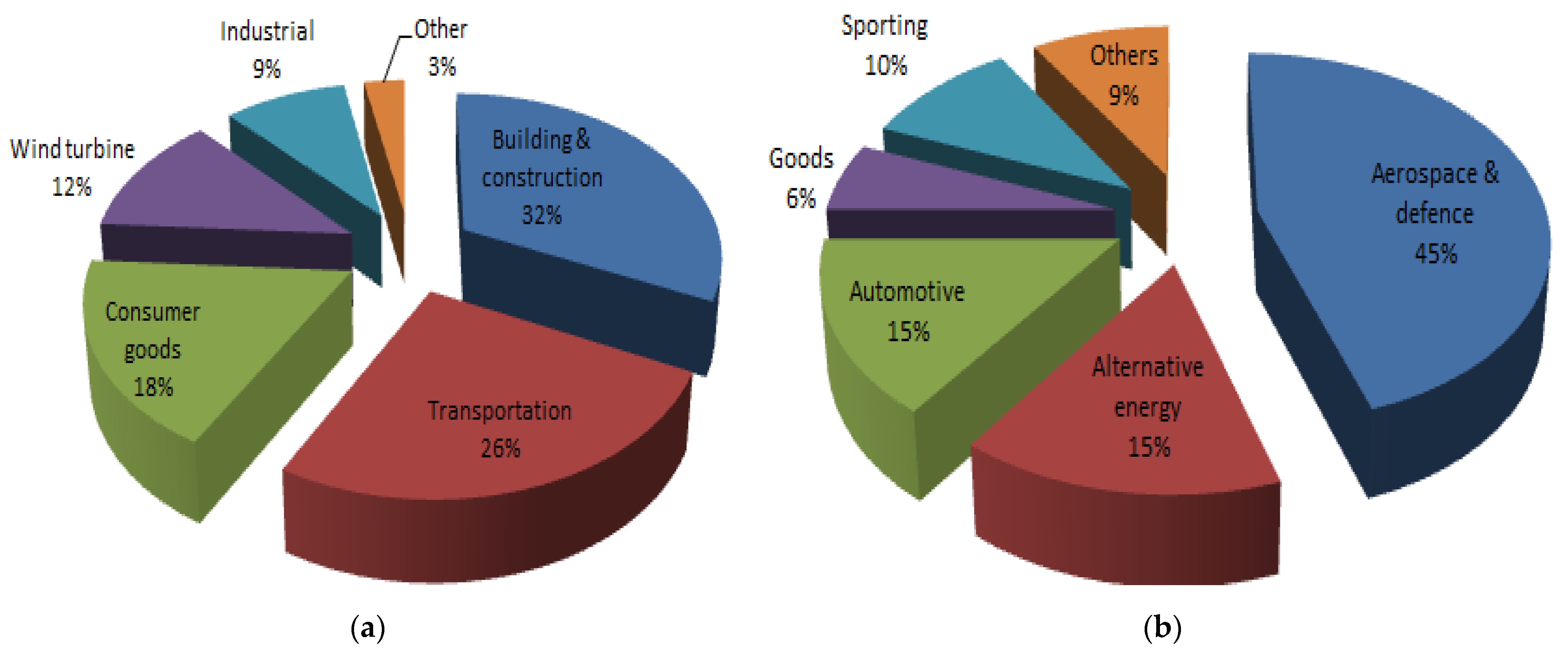
5. Applications of GFRP and CFRP Composites
- ▪
- Space: satellites, space centers, launch vehicles, spaceports, remote manipulator arm, payload bay doors, antenna struts and ribs, high-gain antenna, etc.
- ▪
- Aircraft: floorings and panels of airplanes, drive shafts, elevators, rudders, landing gear doors, bearings, etc.
- ▪
- Marine: offshore construction (seawater piping, stairways and walkways, firewater piping, grating, fire and blast walls, cables and ropes, storage vessels, etc.), valves and strainers, fans and blowers, propeller vanes, gear cases, condenser shells, etc.
- ▪
- Automotive: body panels and doors, engine blocks, drive shafts, automotive racing brakes, clutch plates, filament–wound fuel tanks, push rods, bumpers, frames, valve guides, rocker arm covers, etc.
- ▪
- Civil engineering: the execution of new advanced structures (roofs, plate and shell elements, linear elements, pipes and tanks, folded structures, etc.) and the rehabilitation of existing metallic and concrete structures such as buildings, bridges, pipelines, masonry construction, etc.
- ▪
- Sport industry: golf club shafts, tennis rackets, bicycle framework, fishing rods, etc.
- ▪
- Electrical and Electronics: power line insulators, fiber optics tensile members, lighting poles, etc.
- ▪
- Chemical Industries: racked bottles for fire service, composite vessels for substances, mountain climbing, ducts and stacks, underground storage tanks, etc.
- ▪
- Medical applications: tissue engineering (blood vessels, bone, oral tissues, skin, etc.), wound dressing, dental resin-based composites, etc.
- ▪
- Highway structures: sound barrier, bridge deck, beams, stringer, rebar, abutment panel, dowel bar, signboard and signpost, pole and post, drainage system (pipe, culvert), guardrail system, etc.
- ▪
- Agricultural and industrial buildings: for structural and nonstructural elements.
- ▪
- Renewable energy: wind turbine blades.

6. Conclusions and Future Trends
Author Contributions
Funding
Conflicts of Interest
References
- Weiland, K.; Jones, M.P.; Zinsser, F.; Kontturi, E.; Mautner, A.; Bismarck, A. Grow it yourself composites: Delignification and hybridisation of lignocellulosic material using animals and fungi. Green Chem. 2021, 19, 7506–7514. [Google Scholar] [CrossRef]
- Park, S.; Alammar, A.; Fülöp, Z.; Pulido, B.; Nunes, S.; Szekely, G. Hydrophobic thin film composite nanofiltration membranes derived solely from sustainable sources. Green Chem. 2020, 23, 1175–1184. [Google Scholar] [CrossRef]
- Upton, R.L.; Fedosyuk, A.; Edel, J.B.; Crick, C.R. Carbon Nanofiber/SiO2 Nanoparticle/HDPE composites as physically resilient and submersible water-repellent coatings on HDPE Substrates. ACS Appl. Nano Mater. 2021, 4, 10090–10102. [Google Scholar] [CrossRef]
- Sherif, G.; Chukov, D.; Tcherdyntsev, V.; Torokhov, V. Effect of Formation Route on the Mechanical Properties of the Polyethersulfone Composites Reinforced with Glass Fibers. Polymers 2019, 11, 1364. [Google Scholar] [CrossRef] [Green Version]
- Sun, G.; Yu, H.; Wang, Z.; Xiao, Z.; Li, Q. Energy absorption mechanics and design optimization of CFRP/Alumimun hybrid structures for transverse loading. Int. J. Mech. Sci. 2018, 150, 767–783. [Google Scholar] [CrossRef]
- Yue, H.; Zheng, Y.; Zheng, P.; Guo, J.; Fernández-Blázquez, J.P.; Clark, J.H.; Cui, Y. On the improvement of properties of bioplastic composites derived from wasted cottonseed protein by rational cross-linking and natural fiber reinforcement. Green Chem. 2020, 22, 8642–8655. [Google Scholar] [CrossRef]
- Zheng, S.; D’Angelo, A.; Zell, U.; Chen, Y.; Silverthorne, K.E.C.; Brook, M.A. Naked alpaca wool works better with silicone elastomers. Green Chem. 2021, 23, 7692–7700. [Google Scholar] [CrossRef]
- Ghassemieh, E. Materials in automotive application, state of the art and prospects. New Trends Dev. Automot. Ind. 2011, 20, 365–394. [Google Scholar] [CrossRef] [Green Version]
- Nieuwenhuis, P.; Wells, P. The Automotive Industry and the Environment; Woodhead Publishing: Cambridge, UK, 2003; 272p. [Google Scholar]
- Witik, R.A.; Payet, J.; Michaud, V.; Ludwig, C.; Månson, J.A.E. Assessing the life cycle costs and environmental performance of lightweight materials in automobile applications. Compos. Part A 2011, 42, 1694–1709. [Google Scholar] [CrossRef]
- Acosta Ortiz, R.; Garcia Valdez, A.E.; Garcia Padilla, E.E.; Aguirre Flores, R.; Espinoza Muñoz, J.F. Development of a photocurable glass-fiber reinforced epoxy-amine/thiol-ene composite. J. Polym. Res. 2016, 23, 30. [Google Scholar] [CrossRef]
- Chou, S.; Wu, C. An impact study of epoxy resin composites reinforced with glass fiber fabrics. J. Polym. Res. 1994, 1, 255–264. [Google Scholar] [CrossRef]
- Epasto, G.; Distefano, F.; Gu, L.; Mozafari, H.; Linul, E. Design and optimization of Metallic Foam Shell protective device against flying ballast impact damage in railway axles. Mater. Des. 2020, 196, 109120. [Google Scholar] [CrossRef]
- Linul, E.; Marsavina, L.; Kovacik, J.; Sadowski, T. Dynamic and Quasi-Static Compression Tests of Closed-Cell Aluminium Alloy Foams. Proc. Rom. Acad. Ser. A 2017, 18, 361–369. [Google Scholar]
- Erhard, G.; Thompson, M. Designing with Plastics; Hanser: Munich, Germany, 2006. [Google Scholar]
- Mangalgiri, P.D. Composite materials for aerospace applications. Bull. Mater. Sci. 1999, 22, 657–664. [Google Scholar] [CrossRef] [Green Version]
- Ho, K.C.; Jeng, M.C. Tribological characteristics of short glass fibre reinforced polycarbonate composites. Wear 1997, 206, 60–68. [Google Scholar] [CrossRef]
- Jendli, Z.; Fitoussi, J.; Meraghni, F.; Baptiste, D. Anisotropic strain rate effects on the fibre-matrix interface decohesion in sheet moulding compound composites. Compos. Sci. Technol. 2005, 65, 387–393. [Google Scholar] [CrossRef]
- Anand, P.; Rajesh, D.; Senthil Kumar, M.; Raj, I.S. Investigations on the performances of treated jute/Kenaf hybrid natural fiber reinforced epoxy composite. J. Polym. Res. 2018, 25, 94. [Google Scholar] [CrossRef]
- Fortin, G.Y.; Elbadry, E.A.; Hamada, H. Crashworthiness of recycled cardboard panels reinforced with hybrid columnar aluminum tube-GFRP rods. Polym. Compos. 2019, 40, 4215–4227. [Google Scholar] [CrossRef]
- Jin, Q.; Wang, G.; Liang, T.; Chen, P. Bond-Slip Behavior Between GFRP Bars and Mortar Based on Pull-Out Tests. Polym. Compos. 2019, 40, 2840–2849. [Google Scholar] [CrossRef]
- ASM International Handbook Committee. Engineered Materials Handbook, Volume 1 Composites; ASM International: Almere, OH, USA, 1987; pp. 105–171. [Google Scholar]
- Li, G.; Xian, G.; Li, H. Tension-tension fatigue performance of a large-diameter pultruded carbon/glass hybrid rod. Int. J. Fatig. 2019, 120, 141–149. [Google Scholar] [CrossRef]
- Kar, N.K.; Hu, Y.; Barjasteh, E.; Nutt, S.R. Tension–Tension fatigue of hybrid composite rods. Compos. Part B 2012, 43, 2115–2124. [Google Scholar] [CrossRef]
- Tsai, Y.I.; Bosze, E.J.; Barjasteh, E.; Nutt, S.R. Influence of hygrothermal environment on thermal and mechanical properties of carbon fiber/fiberglass hybrid composites. Compos. Sci. Technol. 2009, 69, 432–437. [Google Scholar] [CrossRef]
- Xian, G.; Guo, R.; Li, C.; Hong, B. Effects of rod size and fiber hybrid mode on the interface shear strength of carbon/glass fiber composite rods exposed to freezing-thawing and outdoor environments. J. Mater. Res. Technol. 2021, 14, 2812–2831. [Google Scholar] [CrossRef]
- Linul, E.; Marsavina, L. Prediction of fracture toughness for open cell polyurethane foams by finite element micromechanical analysis. Iran. Polym. J. 2011, 20, 736–746. [Google Scholar]
- Rajak, D.K.; Wagh, P.H.; Menezes, P.L.; Chaudhary, A.; Kumar, R. Critical overview of coatings technology for Metal Matrix Composites. J. Bio. Tribocorros. 2019, 6, 12. [Google Scholar] [CrossRef]
- Voiconi, T.; Linul, E.; Marşavina, L.; Sadowski, T.; Kneć, M. Determination of flexural properties of rigid PUR foams using digital image correlation. Solid State Phenom. 2014, 216, 116–121. [Google Scholar] [CrossRef]
- Rajak, D.K.; Pagar, D.D.; Kumar, R.; Pruncu, C. Recent progress of reinforcement materials: A comprehensive overview of composite materials. J. Mater. Res. Technol. 2019, 8, 6354–6374. [Google Scholar] [CrossRef]
- Rajak, D.K.; Pagar, D.D.; Menezes, P.L.; Linul, E. Fiber-Reinforced Polymer composites: Manufacturing, properties, and applications. Polymers 2019, 11, 1667. [Google Scholar] [CrossRef] [Green Version]
- Mamalis, A.; Manolakos, D.; Ioannidis, M.; Papapostolou, D. Crashworthy characteristics of axially statically compressed thin-walled square CFRP composite tubes: Experimental. Compos. Struct. 2004, 63, 347–360. [Google Scholar] [CrossRef]
- Linul, E.; Vălean, C.; Linul, P.A. Compressive behavior of aluminum microfibers reinforced semi-rigid polyurethane foams. Polymers 2018, 10, 1298. [Google Scholar] [CrossRef] [Green Version]
- Kim, H.K.; Sohn, J.S.; Ryu, Y.; Kim, S.W.; Cha, S.W. Warpage Reduction of Glass Fiber Reinforced Plastic Using Microcellular Foaming Process Applied Injection Molding. Polymers 2019, 11, 360. [Google Scholar] [CrossRef] [Green Version]
- Ju, M.; Park, K.; Park, C. Punching Shear Behavior of Two-Way Concrete Slabs Reinforced with Glass-Fiber-Reinforced Polymer (GFRP) Bars. Polymers 2018, 10, 893. [Google Scholar] [CrossRef] [Green Version]
- Mishra, S.P. A Text Book of Fibre Science and Technology; New Age International: New Delhi, India, 2000; 363p. [Google Scholar]
- Mane, V.; Markad, C. An overview of glass. Fiber Polym. 2015, 1–15. [Google Scholar]
- Alsalihi, M.A.J. Mechanical Properties of Glass Fiber Reinforced Polymer Bars after Exposure to Elevated Temperatures. Master’s Thesis, The University of Wisconsin–Milwaukee, Milwaukee, WI, USA, 2014. [Google Scholar]
- Sathishkumar, T.P.; Satheeshkumar, S.; Naveen, J. Glass fiber-reinforced polymer composites—A review. J. Reinf. Plastic. Compos. 2014, 33, 1258. [Google Scholar] [CrossRef]
- Roth, S.; Stoll, M.; Weidenmann, K.A.; Coutandin, S.; Fleischer, J. A new process route for the manufacturing of highly formed fiber-metal-laminates with elastomer interlayers (FMEL). Int. J. Adv. Manuf. Technol. 2019, 104, 1293–1301. [Google Scholar] [CrossRef]
- Available online: http://www.matweb.com/ (accessed on 19 March 2020).
- De Souza, A.; Gomes, G.F.; Peres, E.P.; Ancelotti, A.C., Jr. A numerical-experimental evaluation of the fatigue strain limits of CFRP subjected to dynamic compression loads. Int. J. Adv. Manuf. Technol. 2019, 103, 219–237. [Google Scholar] [CrossRef]
- Jeon, Y.P.; Alway-Cooper, R.; Morales, M.; Ogale, A.A. Carbon Fibers, Handbook of Advanced Ceramics, 2nd ed.; Materials, Applications, Processing, and Properties; Academic Press: Cambridge, MA, USA, 2013; pp. 143–154. [Google Scholar] [CrossRef]
- Available online: https://textilelearner.blogspot.com/2012/03/carbon-fiber-characteristicsproperties.html (accessed on 13 March 2020).
- Abhilas, E.; Joseph, M.A. Carbon Fibre Reinforced Aluminum Matrix Composite: Development & Evaluation of Mechanical Behaviors. Processing, Properties, and Performance of Composite Materials. In Proceedings of the Materials Science &Technology (MS&T) 2008 Conference & Exhibition, Pittsburgh, PA, USA, 5–9 October 2008. [Google Scholar]
- Leong, Y.W.; Thitithanasarn, S.; Yamada, K.; Hamada, H. Compression and injection molding techniques for natural fiber composites. In Natural Fibre Composites; Woodhead Publishing: Sawston, UK, 2014; pp. 216–232. [Google Scholar] [CrossRef]
- Werner, V.M.K.; Krumpholz, R.; Rehekampff, C.; Scherzer, T.; Eblenkamp, M. Thermoplastic encapsulations of a sensor platform by high-temperature injection molding up to 360 °C. Polym. Eng. Sci. 2019, 59, 1315–1331. [Google Scholar] [CrossRef]
- González-López, M.E.; Pérez-Fonseca, A.A.; Manríquez-González, R.; Arellano, M.; Rodrigue, D.; Robledo-Ortíz, J.R. Effect of surface treatment on the physical and mechanical properties of injection molded poly(lactic acid)-coir fiber biocomposites. Polym. Compos. 2018, 40, 2132–2141. [Google Scholar] [CrossRef]
- Nagahanumaiah; Ravi, B. Indirect Rapid Tooling. Compr. Mater. Process. 2014, 10, 345–373. [Google Scholar]
- Chung, S.; Im, Y.; Kim, H.; Jeong, H.; Dornfeld, D.A. Evaluation of micro-replication technology using silicone rubber molds and its applications. Int. J. Mach. Tool. Manuf. 2003, 43, 1337–1345. [Google Scholar] [CrossRef]
- Sakata, K.; Ben, G. Fabrication method and compressive properties of CFRP isogrid cylindrical shells. Adv. Compos. Mater. 2012, 21, 445–457. [Google Scholar] [CrossRef]
- Aramide, F.O.; Atanda, P.O.; Olorunniwo, O.O. Mechanical properties of a polyester fibre glass composite. Int. J. Compos. Mater. 2012, 2, 147–151. [Google Scholar]
- Zhao, J. Carbon Fiber Composite Springs and Method of Making Thereof. U.S. Patent Application No. 14/271,424, 18 June 2015. [Google Scholar]
- Xi, Z.; Ghita, O.R.; Evans, K.E. The unusual thermal expansion behaviour of PTFE/GF composites incorporating PTFE/GF recyclate. Compos. Part A 2012, 43, 1999–2006. [Google Scholar] [CrossRef]
- Hameed, N.; Sreekumar, P.A.; Francis, B.; Yang, W.; Thomas, S. Morphology, dynamic mechanical and thermal studies on poly (styrene-co-acrylonitrile) modified epoxy resin/glass fibre composites. Compos. Part A 2007, 38, 2422–2432. [Google Scholar] [CrossRef]
- Chauhan, S.; Kumar, A.; Patnaik, A.; Satapathy, A.; Singh, I. Mechanical and wear characterization of gf reinforced vinyl ester resin composites with different co-monomers. J. Reinf. Plast. Compos. 2008, 28, 2675–2684. [Google Scholar] [CrossRef]
- Yoon, M.-K.; Baidoo, J.; Gillespie, J.W.; Heider, D. Vacuum Assisted Resin Transfer Molding (VARTM) Process Incorporating Gravitational Effects: A Closed-form Solution. J. Compos. Mater. 2005, 39, 2227–2242. [Google Scholar] [CrossRef]
- Uddin, N.; Cauthen, S.; Ramos, L.; Vaidya, U.K. Vacuum assisted resin transfer molding (VARTM) for external strengthening of structures. In Developments in Fiber-Reinforced Polymer (FRP) Composites for Civil Engineering; Wooden Publishing: Cambridge, UK, 2013; pp. 77–114. [Google Scholar]
- Duan, Y.; Tan, Z.; Zhao, Y.; Sun, J. Compression responses of preform in vacuum infusion process. Chin. J. Aeronaut. 2008, 21, 370–377. [Google Scholar]
- Song, X. Vacuum Assisted Resin Transfer Molding (VARTM): Model Development and Verification. Ph.D. Thesis, Virginia Polytechnic Institute and State University, Blacksburg, VA, USA, 2003. [Google Scholar]
- Gajjar, T.; Shah, D.B.; Joshi, S.J.; Patel, K.M. Experimental Study of Thickness Gradient and Flow Simulation in VARTM Process. Fibers Polym 2020, 21, 384–391. [Google Scholar] [CrossRef]
- Gajjar, T.; Shah, D.B.; Joshi, S.J.; Patel, K.M. Analysis of process parameters for composites manufacturing using vacuum infusion process. Mater. Today Proc. 2020, 21, 1244–1249. [Google Scholar] [CrossRef]
- Vila, J.; González, C.; LLorca, J. Fabric compaction and infiltration during vacuum-assisted resin infusion with and without distribution medium. J. Compos. Mater. 2017, 51, 687–703. [Google Scholar] [CrossRef]
- Gajjar, T.; Shah, D.B.; Joshi, S.J.; Patel, K.M. Prediction of spring-back deformation for CFRP reflectors manufactured using various processes. J. Appl. Eng. Res. 2018, 13, 144–148. [Google Scholar]
- Gajjar, T.; Shah, D.B.; Joshi, S.J.; Patel, K.M. Investigation on Dimensional Accuracy for CFRP Antenna Reflectors Using Autoclave and VARTM Processes. In Advances in Computational Methods in Manufacturing; Springer: Berlin/Heidelberg, Germany, 2019; pp. 693–702. [Google Scholar]
- Akif Yalcinkaya, M.; Murat Sozer, E. Effect of part thickness variation on the mold filling time in vacuum infusion process. J. Reinf. Plast. Compos. 2014, 33, 2136–2150. [Google Scholar] [CrossRef]
- Hammami, A.; Gebart, B.R. Analysis of the vacuum infusion molding process. Polym. Compos. 2000, 21, 28–40. [Google Scholar] [CrossRef]
- Hammami, A.; Gebart, B.R. Model for vacuum infusion moulding process. Plast. Rubber Compos. Process. Appl. 1998, 27, 185–189. [Google Scholar]
- Song, X.; Loos, A.C.; Grimsley, B.; Cano, R.; Hubert, P. Simulation of the Vacuum Assisted Resin Transfer Molding Process; Southern Illinois University: Carbondale, IL, USA, 2004. [Google Scholar]
- Konstantopoulos, S.; Hueber, C.; Antoniadis, I.; Summerscales, J.; Schledjewski, R. Liquid composite molding reproducibility in real-world production of fiber reinforced polymeric composites: A review of challenges and solutions. Adv. Manuf. Polym. Compos. Sci. 2019, 5, 85–99. [Google Scholar] [CrossRef]
- Van Oosterom, S.; Allen, T.; Battley, M.; Bickerton, S. An objective comparison of common vacuum assisted resin infusion processes. Compos. Part A 2019, 125, 105528. [Google Scholar] [CrossRef]
- Lionetto, F.; Moscatello, A.; Totaro, G.; Raffone, M.; Maffezzoli, A. Experimental and Numerical Study of Vacuum Resin Infusion of Stiffened Carbon Fiber Reinforced Panels. Materials 2020, 13, 4800. [Google Scholar] [CrossRef] [PubMed]
- Suresha, B.; Chandramohan, G. Three-body abrasives wear behaviour of particulate-filled glass–vinyl ester composites. J. Mater. Process. Technol. 2008, 200, 306–311. [Google Scholar] [CrossRef]
- Perna, A.S.; Viscusi, A.; Astarita, A.; Boccarusso, L.; Carrino, L.; Durante, M.; Sansone, R. Manufacturing of a metal matrix composite coating on a polymer matrix composite through cold gas dynamic spray technique. J. Mater. Eng. Perform. 2019, 28, 3211–3219. [Google Scholar] [CrossRef]
- Marques, A.T. Fibrous materials reinforced composites production techniques. In Fibrous and Composite Materials for Civil Engineering Applications; Woodhead Publishing: Sawston, UK, 2011; pp. 191–215. [Google Scholar] [CrossRef]
- Quanjin, M.; Rejab, M.; Idris, M.; Bachtiar, B.; Siregar, J.; Harith, M. Design and optimize of 3-axis filament winding machine. IOP Conf. Ser. Mater. Sci. Eng. 2017, 257, 012039. [Google Scholar] [CrossRef]
- Frketic, J.; Dickens, T.; Ramakrishnan, S. Automated manufacturing and processing of fiber-reinforced polymer (FRP) composites: An additive review of contemporary and modern techniques for advanced materials manufacturing. Addit. Manuf. 2017, 14, 69–86. [Google Scholar] [CrossRef] [Green Version]
- Laval, C. CADWIND 2006-20 years of filament winding experience. Reinf. Plast. 2006, 50, 34–37. [Google Scholar] [CrossRef]
- Abdalla, F.H.; Mutasher, S.A.; Khalid, Y.A.; Sapuan, S.M.; Hamouda, A.M.S.; Sahari, B.B.; Hamdan, M.M. Design and fabrication of low cost filament winding machine. Mater. Des. 2007, 28, 234–239. [Google Scholar] [CrossRef]
- Mallick, P.K. Fiber-Reinforced Composites: Materials, Manufacturing, and Design; CRC Press: Boca Raton, FL, USA, 1993. [Google Scholar]
- Elmar, W.; Michael, S.; Michael, K. Composites Market Report, Market Developments, Trends, Outlook and Challenges. 2017. Available online: https://www.avk-tv.de/files/20181115_avk_ccev_market_report_2018_final.pdf (accessed on 20 October 2021).
- Sandberg, M.; Yuksel, O.; Comminal, R.B.; Sonne, M.R.; Jabbari, M.; Larsen, M.; Hattel, J.H. Numerical Modeling of the Mechanics of Pultrusion; Mechanics of Materials in Modern Manufacturing Methods and Processing Techniques; Elsevier: Amsterdam, The Netherlands, 2020; pp. 173–195. [Google Scholar] [CrossRef]
- Kafodya, I.; Xian, G.; Li, H. Durability study of pultruded CFRP plates immersed in water and seawater under sustained bending: Water uptake and effects on the mechanical properties. Compos. Part B 2015, 70, 138–148. [Google Scholar] [CrossRef]
- European Pultrusion Technology Association (EPTA). Pultrusion. Available online: https://pultruders.org/pultrusion.php (accessed on 19 January 2021).
- Schafer, J.; Gries, T. Braiding Pultrusion of Thermoplastic Composites, Advances in Braiding Technology; Wooden Publishing: Cambridge, UK, 2016. [Google Scholar] [CrossRef]
- Starr, T. Pultrusion for Engineers; Taylor & Francis: Abingdon, UK, 2000; 336p. [Google Scholar]
- Fiberline Composites. 2019. Available online: https://fiberline.com/news/fiberline-composites-forefront-ce-certification (accessed on 19 January 2021).
- Stefaniak, D.; Kappel, E.; Sprowitz, T.; Huhne, C. Experimental identification of process parameters inducing warpage of autoclave-processed CFRP parts. Compos. Part A 2012, 43, 1081–1091. [Google Scholar] [CrossRef]
- Potter, K. Introduction to Composite Products: Design, Development and Manufacture; Springer Science & Business Media: Berlin/Heidelberg, Germany, 1996; 276p. [Google Scholar]
- Zhang, W.; Wu, J.; Gao, L.; Zhang, B.; Jiang, J.; Hu, J. Recyclable, reprocessable, self-adhered and repairable carbon fiber reinforced polymers using full biobased matrices from camphoric acid and epoxidized soybean oil. Green Chem. 2021, 23, 2763–2772. [Google Scholar] [CrossRef]
- Savignac, L.; Danis, A.S.; Charbonneau, M.; Schougaard, S.B. Valorization of carbon fiber waste from the aeronautics sector: An application in Li-ion batteries. Green Chem. 2021, 23, 2464–2470. [Google Scholar] [CrossRef]
- Castro Protasio, F.; Carino, N.J. Tensile and Nondestructive Testing of FRP Bars. J. Compos. Constr. 1998, 2, 17–27. [Google Scholar] [CrossRef]
- Bakis, C.E.; Nanni, A.; Terosky, J.A. Smart, Pseudo-ductile, Reinforcing Rods for Concrete: Manufacture and Test. In Proceedings of the First International Conference on Composites in Infrastructure, Tucson, AZ, USA, 15–17 January 1996; pp. 95–108. [Google Scholar]
- Chen, Z.; Liu, X.; Lü, R.; Li, T. Mechanical and tribological properties of PA66/PPS blend. III. Reinforced with GF. J. Appl. Polym. Sci. 2006, 102, 523–529. [Google Scholar] [CrossRef]
- Faizal, M.A.; Beng, Y.K.; Dalimin, M.N. Tensile property of hand lay-up plain-weave woven e glass/polyester composite: Curing pressure and ply arrangement effect. Borneo Sci. 2006, 19, 27–34. [Google Scholar]
- Khalili, S.M.R.; Mittal, R.K.; Kalibar, S.G. A study of the mechanical properties of steel/aluminium/GRP laminates. Mater. Sci. Eng. A 2005, 412, 137–140. [Google Scholar] [CrossRef]
- Soden, P.D.; Hinton, M.J.; Kaddour, A.S. Lamina properties, lay-up configurations and loading conditions for a range of fibre-reinforced composite laminates. Compos. Sci. Technol. 1998, 58, 1011–1022. [Google Scholar] [CrossRef]
- Vallittu, P.K.; Lassila, V.P.; Lappalainen, R. Transverse strength and fatigue of denture acrylic-glass fiber composite. Dent. Mater. 1994, 10, 116–121. [Google Scholar] [CrossRef]
- Withers, G.J.; Yu, Y.; Khabashesku, V.N.; Cercone, L.; Hadjiev, V.G.; Souza, J.M.; Davis, D.C. Improved mechanical properties of an epoxy glass–fiber composite reinforced with surface organomodified nanoclays. Compos. Part B 2015, 72, 175–182. [Google Scholar] [CrossRef]
- Patnaik, A.; Satapathy, A.; Biswas, S. Investigations on three-body abrasive wear and mechanical properties of particulate filled glass epoxy composites. Malays. Polym. J. 2010, 5, 37–48. [Google Scholar]
- Al-alkawi, J.H.; Al-Fattal, S.D.; Ali, H.A.J. Fatigue behavior of woven glass fiber reinforced polyester under variable temperature. Elixir. Mech. Eng. 2012, 53, 12045–12050. [Google Scholar]
- Abdurohman, K.; Satrio, T.; Muzayadah, N.L.; Teten. A comparison process between hand lay-up, vacuum infusion and vacuum bagging method toward e-glass EW 185/lycal composites. J. Phys. Conf. Ser. 2018, 1130, 012018. [Google Scholar] [CrossRef]
- Torabizadeh, M.A. Tensile, compressive and shear properties of unidirectional glass/epoxy composites subjected to mechanical loading and low temperature services. Indian J. Eng. Mater. Sci. 2013, 20, 299–309. [Google Scholar]
- Godara, A.; Raabe, D. Influence of fiber orientation on global mechanical behavior and mesoscale strain localization in a short glass-fiber-reinforced epoxy polymer composite during tensile deformation investigated using digital image correlation. Compos. Sci. Technol. 2007, 67, 2417–2427. [Google Scholar] [CrossRef]
- Leonard, L.W.H.; Wong, K.J.; Low, K.O.; Yousif, B.F. Fracture behaviour of glass fibre-reinforced polyester composite. Proc. Inst. Mech. Eng. Part L 2009, 223, 83–89. [Google Scholar] [CrossRef] [Green Version]
- Suresha, B.; Chandramohan, G.; Renukappa, N.M. Mechanical and tribological properties of glass–epoxy composites with and without graphite particulate filler. J. Appl. Polym. Sci. 2006, 103, 2472–2480. [Google Scholar] [CrossRef]
- Biswas, S.; Satapathy, A. A Study on Tribological Behavior of Alumina-Filled Glass–Epoxy Composites Using Taguchi Experimental Design. Tribol. Trans. 2010, 53, 520–532. [Google Scholar] [CrossRef]
- Sudheer, M.; Hemanth, K.; Raju, K.; Bhat, T. Enhanced Mechanical and Wear Performance of Epoxy/glass Composites with PTW/Graphite Hybrid Fillers. Proc. Mater. Sci. 2014, 6, 975–987. [Google Scholar] [CrossRef] [Green Version]
- Alam, S.; Habib, F.; Irfan, M.; Iqbal, W.; Khalid, K. Effect of orientation of glass fiber on mechanical properties of GRP composites. J. Chem. Soc. Pak. 2010, 32, 265–269. [Google Scholar]
- Gupta, N.; Singh Brar, B.; Woldesenbet, E. Effect of filler addition on the compressive and impact properties of glass fibre reinforced epoxy. Bull. Mater. Sci. 2001, 24, 219–223. [Google Scholar] [CrossRef]
- Karippal, J.J.; Narasimha Murthy, H.N.; Rai, K.S.; Sreejith, M.; Krishna, M. Study of mechanical properties of epoxy/glass/nanoclay hybrid composites. J. Compos. Mater. 2011, 45, 1893–1899. [Google Scholar] [CrossRef]
- Yuanjian, T.; Isaac, D.H. Combined impact and fatigue of glass fiber reinforced composites. Compos. Part B 2008, 39, 505–512. [Google Scholar] [CrossRef]
- Botelho, E. Mechanical behavior of carbon fiber reinforced polyamide composites. Compos. Sci. Technol. 2003, 63, 1843–1855. [Google Scholar] [CrossRef]
- Zhou, S.; Zhang, Q.; Wu, C.; Huang, J. Effect of carbon fiber reinforcement on the mechanical and tribological properties of polyamide6/polyphenylene sulfide composites. Mater. Des. 2013, 44, 493–499. [Google Scholar] [CrossRef]
- Li, J. The effect of surface modification with nitric acid on the mechanical and tribological properties of carbon fiber-reinforced thermoplastic polyimide composite. Surf. Interface Anal. 2009, 41, 759–763. [Google Scholar] [CrossRef]
- Luo, W.; Liu, Q.; Li, Y.; Zhou, S.; Zou, H.; Liang, M. Enhanced mechanical and tribological properties in polyphenylene sulfide/polytetrafluoroethylene composites reinforced by short carbon fiber. Compos. Part B 2016, 91, 579–588. [Google Scholar] [CrossRef]
- Hussain, M.; Nakahira, A.; Niihara, K. Mechanical property improvement of carbon fiber reinforced epoxy composites by Al2O3 filler dispersion. Mater. Lett. 1996, 26, 185–191. [Google Scholar] [CrossRef]
- Torbjörner, A.; Karlsson, S.; Syverud, M.; Hensten-Pettersen, A. Carbon fiber reinforced root canal posts Mechanical and cytotoxic properties. Eur. J. Oral Sci. 1996, 104, 605–611. [Google Scholar] [CrossRef] [PubMed]
- Shim, H.-B.; Seo, M.-K.; Park, S.-J. Thermal conductivity and mechanical properties of various cross-section types carbon fiber-reinforced composites. J. Mater. Sci. 2002, 37, 1881–1885. [Google Scholar] [CrossRef]
- Ozkan, C.; Gamze Karsli, N.; Aytac, A.; Deniz, V. Short carbon fiber reinforced polycarbonate composites: Effects of different sizing materials. Compos. Part B 2014, 62, 230–235. [Google Scholar] [CrossRef]
- Zhou, Y.; Pervin, F.; Jeelani, S.; Mallick, P.K. Improvement in mechanical properties of carbon fabric–epoxy composite using carbon nanofibers. J. Mater. Process. Technol. 2008, 198, 445–453. [Google Scholar] [CrossRef]
- Shariatnia, S.; Kumar, A.V.; Kaynan, O.; Asadi, A. Hybrid Cellulose Nanocrystals-Bonded Carbon Nanotubes/Carbon Fiber Polymer Composites for Structural Applications. ACS Appl. Nano Mater. 2020, 3, 5421–5436. [Google Scholar] [CrossRef]
- Castellano, A.; Foti, P.; Fraddosio, A.; Marzano, S.; Piccioni, M.D. Mechanical characterization of CFRP composites by ultrasonic immersion tests: Experimental and numerical approaches. Compos. Part B 2014, 66, 299–310. [Google Scholar] [CrossRef]
- Zhang, Z.; Wilson, J.L.; Kitt, B.R.; Flaherty, D.W. Effects of Oxygen Plasma Treatments on Surface Functional Groups and Shear Strength of Carbon Fiber Composites. ACS Appl. Nano Mater. 2021, 3, 986–995. [Google Scholar] [CrossRef]
- Richardson, M.O.W.; Wisheart, M.J. Review of low-velocity impact properties of composite materials. Compos. Part A 1996, 27, 1123–1131. [Google Scholar] [CrossRef]
- Castellano, A.; Fraddosio, A.; Piccioni, M.D. Quantitative analysis of QSI and LVI damage in GFRP unidirectional composite laminates by a new ultrasonic approach. Compos. Part B 2018, 151, 106–117. [Google Scholar] [CrossRef]
- Aoki, Y.; Suemasu, H.; Ishikawa, T. Damage propagation in CFRP laminates subjected to low velocity impact and static indentation. Adv. Compos. Mater. 2007, 16, 45–61. [Google Scholar] [CrossRef]
- Lee, S.M.; Zahuta, P. Instrumented impact and static indentation of composites. J. Compos. Mater. 1991, 25, 204–222. [Google Scholar] [CrossRef] [Green Version]
- Karakassides, A.; Ganguly, A.; Tsirka, K.; Paipetis, A.S.; Papakonstantinou, P. Radially grown graphene nanoflakes on carbon fibres as reinforcing interface for polymer composites. ACS Appl. Nano Mater. 2020, 3, 2402–2413. [Google Scholar] [CrossRef] [Green Version]
- Pietras, D.; Linul, E.; Sadowski, T.; Rusinek, A. Out-of-plane crushing response of aluminum honeycombs in-situ filled with graphene-reinforced polyurethane foam. Compos. Struct. 2020, 249, 112548. [Google Scholar] [CrossRef]
- Khezrzadeh, O.; Mirzaee, O.; Emadoddin, E.; Linul, E. Anisotropic compressive behavior of metallic foams under extreme temperature conditions. Materials 2020, 13, 2329. [Google Scholar] [CrossRef] [PubMed]
- Adams, R.D.; Flitcroft, J.E.; Hancox, N.L.; Reynolds, W.N. Effects of shear damage on the torsional behaviour of carbon fibre reinforced plastics. J. Compos. Mater. 1973, 7, 68–75. [Google Scholar] [CrossRef]
- Marsavina, L.; Kováčik, J.; Linul, E. Experimental validation of micromechanical models for brittle aluminium alloy foam. Theor. Appl. Fract. Mech. 2016, 83, 11–18. [Google Scholar] [CrossRef]
- Cottell, G.A.; Entwistle, K.M.; Thompson, F.C. The measurement of damping capacity of metals in torsional vibration. J. Inst. Met. 1948, 74, 373–424. [Google Scholar]
- Hemmatnezhad, M.; Rahimi, G.H.; Tajik, M.; Pellicano, F. Experimental, numerical and analytical investigation of free vibrational behavior of GFRP-stiffened composite cylindrical shells. Compos. Struct. 2015, 120, 509–518. [Google Scholar] [CrossRef]
- Yuvaraja, M.; Senthilkumar, M. Comparative Study on Vibration Characteristics of a Flexible GFRP Composite Beam Using SMA and PZT Actuators. Procedia Eng. 2013, 64, 571–581. [Google Scholar] [CrossRef] [Green Version]
- Awad, Z.K.; Aravinthan, T.; Zhuge, Y. Investigation of the free vibration behaviour of an innovative GFRP sandwich floor panel. Constr. Build. Mater. 2012, 37, 209–219. [Google Scholar] [CrossRef]
- Bledzki, A.; Kessler, A.; Rikards, R.; Chate, A. Determination of elastic constants of glass/epoxy unidirectional laminates by the vibration testing of plates. Compos. Sci. Technol. 1999, 59, 2015–2024. [Google Scholar] [CrossRef]
- Naghipour, M.; Taheri, F.; Zou, G.P. Evaluation of Vibration Damping of Glass-Reinforced-Polymer-Reinforced Glulam Composite Beams. J. Struct. Eng. 2005, 131, 1044–1050. [Google Scholar] [CrossRef]
- Gürgen, S.; Sofuoğlu, M.A. Experimental investigation on vibration characteristics of shear thickening fluid filled CFRP tubes. Compos. Struct. 2019, 226, 111236. [Google Scholar] [CrossRef]
- Sargianis, J.; Suhr, J. Core material effect on wave number and vibrational damping characteristics in carbon fiber sandwich composites. Compos. Sci. Technol. 2012, 72, 1493–1499. [Google Scholar] [CrossRef]
- Lin, D.X.; Ni, R.G.; Adams, R.D. Prediction and Measurement of the Vibrational Damping Parameters of Carbon and Glass Fibre-Reinforced Plastics Plates. J. Compos. Mater. 1984, 18, 132–152. [Google Scholar] [CrossRef]
- Ray, B.C.; Rathore, D. Durability and integrity studies of environmentally conditioned interfaces in fibrous polymeric composites: Critical concepts and comments. Adv. Colloid Interface Sci. 2014, 209, 68–83. [Google Scholar] [CrossRef] [PubMed]
- Guigon, M.; Klinklin, E. The interface and interphase in carbon fibre-reinforced composites. Composites 1994, 25, 534–539. [Google Scholar] [CrossRef]
- Stoia, D.I.; Linul, E.; Marsavina, L. Influence of Manufacturing Parameters on Mechanical Properties of Porous Materials by Selective Laser Sintering. Materials 2019, 12, 871. [Google Scholar] [CrossRef] [Green Version]
- Marsavina, L.; Linul, E. Fracture toughness of rigid polymeric foams: A review. Fatig. Fract. Eng. Mater. Struct. 2020, 43, 2483–2514. [Google Scholar] [CrossRef]
- Linul, E.; Marşavina, L.; Vălean, C.; Bănică, R. Static and dynamic mode I fracture toughness of rigid PUR foams under room and cryogenic temperatures. Eng. Fract. Mech. 2020, 225, 106274. [Google Scholar] [CrossRef]
- Ray, B.C. Effects of Changing Environment and Loading Speed on Mechanical Behavior of FRP Composites. J. Reinf. Plast. Compos. 2006, 25, 1227–1240. [Google Scholar] [CrossRef]
- Mishra, G.; Mohapatra, S.; Behera, P.; Dash, B.; Mohanty, U.; Ray, B. Environmental stability of GFRP laminated composites: An emphasis on mechanical behavior. Aircraft Eng. Aerosp. Technol. 2010, 82, 258–266. [Google Scholar] [CrossRef]
- Araújo, E.M.; Araújo, K.D.; Pereira, O.D.; Ribeiro, P.C.; Melo, T.J.A. Fiberglass wastes/polyester resin composites: Mechanical properties and water sorption. Polímeros 2006, 16, 332–335. [Google Scholar] [CrossRef]
- Botelho, E.C.; Bravim Júnior, J.C.; Costa, M.L.; De Faria, M.C.M. Environmental Effects on Thermal Properties of PEI/Glass Fiber Composite Materials. J. Aerosp. Technol. Manag. 2013, 5, 241–254. [Google Scholar] [CrossRef]
- Ellyin, F.; Maser, R. Environmental effects on the mechanical properties of glass-fiber epoxy composite tubular specimens. Compos. Sci. Technol. 2004, 64, 1863–1874. [Google Scholar] [CrossRef]
- Abbasi, A.; Hogg, P.J. Temperature and environmental effects on glass fibre rebar: Modulus, strength and interfacial bond strength with concrete. Compos. Part B 2005, 36, 394–404. [Google Scholar] [CrossRef]
- Zhou, J.; Lucas, J.P. The effects of a water environment on anomalous absorption behavior in graphite/epoxy composites. Compos. Sci. Technol. 1995, 53, 57–64. [Google Scholar] [CrossRef]
- Shan, Y.; Liao, K. Environmental fatigue behavior and life prediction of unidirectional glass-carbon/epoxy hybrid composites. Int. J. Fatig. 2001, 24, 847–859. [Google Scholar] [CrossRef]
- Dickson, R.F.; Jones, C.J.; Harris, B.; Leach, D.C.; Moore, D.R. The environmental fatigue behaviour of carbon fibre reinforced polyether ether ketone. J. Mater. Sci. 1985, 20, 60–70. [Google Scholar] [CrossRef]
- Srivastava, V.K.; Wahne, S. Wear and friction behaviour of soft particles filled random direction short GFRP composites. Mater. Sci. Eng. A 2007, 458, 25–33. [Google Scholar] [CrossRef]
- Srinivasan, V.; Karthikeyan, R.; Raffi, N.M.; Ganesan, G. Wear Characterisitcs of Nano-Particle Filled GFRP Composites. Adv. Compos. Lett. 2010, 19, 5–16. [Google Scholar] [CrossRef] [Green Version]
- Kishore Sampathkumaran, P.; Seetharamu, S.; Vynatheya, S.; Murali, A.; Jumar, R.K. SEM observations of the effects of velocity and load on the sliding wear characteristics of glass fabric–epoxy composites with different fillers. Wear 2000, 237, 20–27. [Google Scholar] [CrossRef]
- Kishore Sampathkumaran, P.; Seetharamu, S.; Murali, A.; Kumar, R. On the SEM features of glass–epoxy composite system subjected to dry sliding wear. Wear 2001, 247, 208–213. [Google Scholar] [CrossRef]
- Yousif, B.F.; El-Tayeb, N.S.M. Wear and friction characteristics of CGRP composite under wet contact condition using two different test techniques. Wear 2008, 265, 856–864. [Google Scholar] [CrossRef]
- Mohan, N.; Natarajan, S.; KumareshBabu, S.P. Investigation on sliding wear behaviour and mechanical properties of jatropha oil cake-filled glass-epoxy composites. J. Am. Oil Chem. Soc. 2010, 88, 111–117. [Google Scholar] [CrossRef]
- Chauhan, S.R.; Kumar, A.; Singh, I. Study on friction and sliding wear behavior of woven S-glass fiber reinforced vinylester composites manufactured with different comonomers. J. Mater. Sci. 2009, 44, 6338–6347. [Google Scholar] [CrossRef]
- Chang, L.; Zhang, Z.; Zhang, H.; Friedrich, K. Effect of nanoparticles on the tribological behaviour of short carbon fibre reinforced poly(etherimide) composites. Tribol. Int. 2005, 38, 966–973. [Google Scholar] [CrossRef]
- Xu, Y.; Zhang, Y.; Cheng, L.; Zhang, L.; Lou, J.; Zhang, J. Preparation and friction behavior of carbon fiber reinforced silicon carbide matrix composites. Ceram. Int. 2007, 33, 439–445. [Google Scholar] [CrossRef]
- Werner, P.; Altstädt, V.; Jaskulka, R.; Jacobs, O.; Sandler, J.K.W.; Shaffer, M.S.P. Tribological behaviour of carbon-nanofibre-reinforced poly(ether ether ketone). Wear 2004, 257, 1006–1014. [Google Scholar] [CrossRef]
- Caruso, J.; Cristos, C.C. Assessment of simplified composite micromechanics using three dimensional finite element analysi. J. Compos. Technol. Res. 1986, 8, 77–83. [Google Scholar]
- Hashin, Z. Analysis of properties of fiber composites with anisotropic constituents. ASME Appl. Mech 1979, 46, 543–550. [Google Scholar] [CrossRef]
- Springer, G.S.; Tsai, S.W. Thermal conductivity of unidirectional materials. J. Compos. Mater. 1967, 1, 166–173. [Google Scholar] [CrossRef]
- Muralidhar, K. Equivalent conduction of a heterogeneous medium. Int. J. Heat Mass Trans. 1989, 33, 1759–1766. [Google Scholar] [CrossRef]
- Gowayed, Y.; Hwang, J.C. Thermal conductivity of composite materials made from plain weaves and 3-D weaves. Compos. Eng. 1995, 5, 1177–1186. [Google Scholar] [CrossRef]
- Yung, K.; Zhu, B.; Yue, T.; Xie, C. Preparation and properties of hollow glass microsphere-filled epoxy-matrix composites. Compos. Sci. Technol. 2009, 69, 260–264. [Google Scholar] [CrossRef]
- López, F.A.; Martín, M.I.; Alguacil, F.J.; Rincón, J.M.; Centeno, T.A.; Romero, M. Thermolysis of fibreglass polyester composite and reutilisation of the glass fibre residue to obtain a glass–ceramic material. J. Anal. Appl. Pyrolysis 2012, 93, 104–112. [Google Scholar] [CrossRef] [Green Version]
- Phonthammachai, N.; Li, X.; Wong, S.; Chia, H.; Tjiu, W.W.; He, C. Fabrication of CFRP from high performance clay/epoxy nanocomposite: Preparation conditions, thermal–mechanical properties and interlaminar fracture characteristics. Compos. Part A 2011, 42, 881–887. [Google Scholar] [CrossRef]
- Jerz, J.; Mináriková, N.; Marsavina, L.; Linul, E. Scaling of compression strength in disordered solids: Metallic foams. Frat. Ed Integrita Strutt. 2016, 10, 55–62. [Google Scholar] [CrossRef] [Green Version]
- Rao, H.G.; Liang, R. Applications of fiber reinforced polymer composites. ICERP 2006, 2006, 23–25. [Google Scholar]
- Chun, H.; Guo, X.; Kim, J.S.; Lee, C.B. A review: Additive manufacturing of flexure mechanism for nanopositioning system. Int. J. Adv. Manuf. Technol. 2020, 110, 681–703. [Google Scholar] [CrossRef]
- Golewski, G.L. The Beneficial Effect of the Addition of Fly Ash on Reduction of the Size of Microcracks in the ITZ of Concrete Composites under Dynamic Loading. Energies 2021, 14, 668. [Google Scholar] [CrossRef]
- Golewski, G.L.; Gil, D.M. Studies of Fracture Toughness in Concretes Containing Fly Ash and Silica Fume in the First 28 Days of Curing. Materials 2021, 14, 319. [Google Scholar] [CrossRef]
- Adesina, O.T.; Jamiru, T.; Sadiku, E.R.; Ogunbiyi, O.F.; Beneke, L.W. Mechanical evaluation of hybrid natural fibre–reinforced polymeric composites for automotive bumper beam: A review. Int. J. Adv. Manuf. Technol. 2019, 103, 1781–1797. [Google Scholar] [CrossRef]
- Marsavina, L.; Constantinescu, D.M.; Linul, E.; Stuparu, F.A.; Apostol, D.A. Experimental and numerical crack paths in PUR foams. Eng. Fract. Mech. 2016, 167, 68–83. [Google Scholar] [CrossRef]
- Soutis, C. Fibre reinforced composites in aircraft construction. Prog. Aerosp. Sci. 2005, 41, 143–151. [Google Scholar] [CrossRef]
- Aamir, M.; Tolouei-Rad, M.; Giasin, K.; Nosrati, A. Recent advances in drilling of carbon fiber–reinforced polymers for aerospace applications: A review. Int. J. Adv. Manuf. Technol. 2019, 105, 2289–2308. [Google Scholar] [CrossRef]
- Szostak, B.; Golewski, G.L. Improvement of Strength Parameters of Cement Matrix with the Addition of Siliceous Fly Ash by Using Nanometric C-S-H Seeds. Energies 2020, 13, 6734. [Google Scholar] [CrossRef]
- Golewski, G.L. New principles for implementation and operation of foundations for machines: A review of recent advances. Struct. Eng. Mech. 2019, 71, 317–327. [Google Scholar]
- Stoia, D.I.; Marşavina, L.; Linul, E. Correlations between Process Parameters and Outcome Properties of Laser-Sintered Polyamide. Polymers 2019, 11, 1850. [Google Scholar] [CrossRef] [PubMed] [Green Version]
- Available online: https://www.transparencymarketresearch.com/glass-fibers-market.html (accessed on 11 March 2020).
- Available online: https://www.mordorintelligence.com/industry-reports/carbon-fiber-market (accessed on 22 April 2020).
- Nash, N.H.; Portela, A.; Bachour, C.; Manolakis, I. Effect of environmental conditioning on the properties of thermosetting- and thermoplastic-matrix composite materials by resin infusion for marine applications. Compos. Part B 2019, 177, 107271. [Google Scholar] [CrossRef]
- Ricciardi, M.R.; Papa, I.; Antonucci, V.; Lopresto, V.; Langella, A. Impact behavior of polyester GFRP for naval applications: Influence of the clamping device and fluid–material interaction. J. Mater. Eng. Perform. 2019, 28, 3196–3202. [Google Scholar] [CrossRef]
- Crupi, V.; Palomba, G. Design of honeycomb structures for naval applications. In Proceedings of the 18th International Congress of the Maritme Association of the Mediterranean, Varna, Bulgaria, 9–11 September 2019; CRC Press: Boca Raton, FL, USA, 2019. [Google Scholar]
- Rahmanian, S.; Thean, K.S.; Suraya, A.R.; Shazed, M.A.; Salleh, M.M.; Yusoff, H.M. Carbon and glass hierarchical fibers: Influence of carbon nanotubes on tensile, flexural and impact properties of short fiber reinforced composites. Mater. Des. 2013, 43, 10–16. [Google Scholar] [CrossRef]
- Ramesh, M.; Palanikumar, K.; Reddy, K.H. Mechanical property evaluation of sisal–jute–glass fiber reinforced polyester composites. Compos. Part B 2013, 48, 1–9. [Google Scholar] [CrossRef]
- Forintos, N.; Czigány, T. Multifunctional application of carbon fiber reinforced polymer composites: Electrical properties of the reinforcing carbon fibers—A short review. Compos. Part B 2019, 162, 331–343. [Google Scholar] [CrossRef]
- Chabaud, G.; Castro, M.; Denoual, C.; Le Duigou, A. Hygromechanical properties of 3D printed continuous carbon and glass fibre reinforced polyamide composite for outdoor structural applications. Addit. Manuf. 2019, 26, 94–105. [Google Scholar] [CrossRef]
- Akderya, T.; Çevik, M. Investigation of thermal-oil environmental ageing effect on mechanical and thermal behaviours of E-glass fibre/epoxy composites. J. Polym. Res. 2018, 25, 214. [Google Scholar] [CrossRef]
- Jiang, X.; Luo, C.; Qiang, X.; Zhang, Q.; Kolstein, H.; Bijlaard, F. Coupled Hygro-Mechanical Finite Element Method on Determination of the Interlaminar Shear Modulus of Glass Fiber-Reinforced Polymer Laminates in Bridge Decks under Hygrothermal Aging Effects. Polymers 2018, 10, 845. [Google Scholar] [CrossRef] [PubMed] [Green Version]
- Available online: https://www.gminsights.com/industry-analysis/fiber-reinforced-polymer-frp-rebars-market (accessed on 8 March 2020).
- Available online: https://www.variantmarketresearch.com/report-categories/automotive/marine-propulsion-engine-market (accessed on 19 June 2020).
- Friedrich, K.; Almajid, A.A. Manufacturing Aspects of Advanced Polymer Composites for Automotive Applications. Appl. Composi. Mater. 2012, 20, 107–128. [Google Scholar] [CrossRef]
- Pingkuo, L.; Yi, G. Graphene’s potential in the future industrial development of China. Resour. Policy 2019, 61, 118–127. [Google Scholar] [CrossRef]
- Huang, J.; Ouyang, Q.; Li, M.; Heng, F.; Ma, H.; Chen, Y. Thermal behavior and thermal stabilization of guanidine hydrochloride-modified acrylic fiber for preparation of low-cost carbon fiber. J. Therm. Anal. Calorim. 2018, 136, 2195–2203. [Google Scholar] [CrossRef]
- Yang, J.Y.; Chen, L.; Tang, Z. Shang Gong Europe: The Odyssey of a State-Owned Chinese Enterprise to the West. Management for Professionals. In Chinese M&As in Germany; Springer: Berlin, Germany, 2018; pp. 19–43. [Google Scholar] [CrossRef]
- Drifte, R. Arms Production in Japan: The Military Applications of Civilian Technology; eBook; Routledge: New York, NY, USA, 2019; 148p. [Google Scholar]


| Fiber Category | Composition | Characteristics | Applications |
|---|---|---|---|
| A-Glass | alkali-lime glass with little or no boron oxide |
|
|
| C-Glass | alkali-lime glass with high boron oxide content | resistant to chemical attack and most acids which dissolve e-glass | when higher chemical resistance to acid-induced corrosion is required: glass staple fibers and insulation |
| D-Glass | borosilicate glass | low dielectric constant | when low dielectric constant is preferred |
| E-Glass | alumino-borosilicate glass with less than 1 wt.% alkali oxides |
|
|
| AR-Glass | resistant to alkali environment |
| |
| R-Glass | alumino-silicate glass without MgO and CaO content |
|
|
| S-Glass | alumino-silicate glass without CaO but with high MgO content |
|
|
| Properties | Type of Glass Fiber | ||||||||
|---|---|---|---|---|---|---|---|---|---|
| A | C | D | E | AR | R | S | S-2 | ||
| Physical | Density (g/cm3) | 2.44 | 2.52–2.56 | 2.11–2.14 | 2.54–2.60 | 2.70 | 2.54 | 2.48–2.49 | 2.46 |
| Mechanical | Tensile Strength (MPa) | 3310 | 3310 | 2415 | 3450 | 3241 | 4135 | 4585 | 4890 |
| Elongation at Break (%) | 4.8 | 4.8 | 4.6 | 4.8 | 4.4 | 4.8 | 5.4 | 5.7 | |
| Young’s Modulus (GPa) | 68.9 | 68.9 | 51.7 | 72.4 | 73.1 | 85.5 | 85.5–46.9 | 46.9 | |
| Poisson’s Ratio (-) | 0.183 | 0.276 | 0.200 | 0.22 | 0.230 | ||||
| Shear Modulus (GPa) | 29.1 | 27.0 | 30.0 | 35.0 | 35.0 | ||||
| Electrical | Electrical Resistivity (Ω-cm) | 108 | - | 4.02 × 10¹² | 2.03 ×10¹² | 9.05 × 10¹⁰ | 9.05 × 10¹⁰ | ||
| Dielectric Constant (-) | 6.2 | 6.9 | 3.8 | 5.9–6.4 | 8.1 | 6.4 | 5.1–5.34 | 5.3 | |
| Dissipation Factor (-) | - | 0.0085 | 0.0025 | 0.0034 | |||||
| Dielectric Strength (kV/mm) | 10.3 | 13.0 | |||||||
| Thermal | CTE, linear (μm/m-°C) | 9.0 | 6.3 | 2.5 | 5.0 | 6.5 | 3.3 | 5.2–5.6 | 1.6 |
| Specific Heat Capacity (J/g-°C) | 0.796 | 0.787 | 0.733 | 0.810 | 0.732 | 0.737 | 0.737 | ||
| Softening Point (°C) | 727.0 | 750 | 771 | 840.6 | 773 | 952 | 1056 | ||
| Thermal Conductivity (W/m-K) | - | 1.1 | 1.3 | 1.45 | |||||
| Thermal expansion coeff. (×10−7) | 73 | 63 | 25 | 54 | 65 | 33 | 16 | ||
| Melting Point (°C) | ≥1725 | ≥1725 | |||||||
| Annealing point (°C) | 588 | 521 | 657 | 816 | |||||
| Strain point (°C) | 522 | 477 | 615 | 736 | 766 | ||||
| Optical | Refractive Index (-) | 1.538 | 1.533 | 1.465 | 1.558 | 1.562 | 1.546 | 1.525 | 1.521 |
| Fiber Type | Precursor Material | Density (g/cm3) | Tenacity (GPa) | Modulus (GPa) | Breaking Extension (%) | Characteristics | Applications |
|---|---|---|---|---|---|---|---|
| HS | PAN | 1.7–1.8 | 2.8–4 | 230–250 | 1.0–2.0 |
|
|
| UHS | PAN | 1.7–1.8 | 4.1–5.7 | 260–290 | 0.8–1.0 |
|
|
| LM | Pitch | 1.3–1.7 | 0.6–1.0 | 40–60 | 2.0–5.0 |
|
|
| HM | PAN/Mesophase pitch | 1.8–2.0 | 1.7–3.5 | 450–750 | 0.5 |
|
|
| UHM | Mesophase pitch | 2.0–2.2 | 2.1–2.4 | 600–900 | 0.2 |
|
|
| Reference | Type of GF | Resin | Curing Agent | Volume of Fiber (%) | Process Type | Sample Thickness (mm) | Testing Standard | Tensile Strength (MPa) | Flexural Strength (MPa) | Elongation at Break (%) |
|---|---|---|---|---|---|---|---|---|---|---|
| [98] | E-glass fiber | Heat-cured acrylic resin | - | - | Pultrusion | 2.17 ± 0.15 | - | - | 265.4 | 1.000 |
| [99] | E-glass fiber | Bispenol a type epoxy resin | Blend of TEPA and NP) | - | Autoclave | 2.5 | - | 270 | - | - |
| [100] | Randomly Oriented | Epoxy (10 wt.% Sic) | - | 4.817 | Hand lay-up | - | ASTM D 3039-76 (T), D 256 (I) | 179.4 | 297.82 | - |
| [101] | Woven mat | Polyester | - | - | - | - | ASTM D 638-97 (T) | 249 | - | - |
| [102] | E-glass fiber | epoxy resin (lycal type) | - | 61 | Hand lay-up | 2.96 | ASTM D3039/D3039M-17 | 260.98 | - | 6 |
| [103] | Unidirectional | Epoxy | - | 55 | Hand lay-up | 2 | ASTM D3039 (T) | 784.98 | 0.032 | |
| [104] | Woven + (35 wt.% Short Borosilicate) | Epoxy | - | - | Hand lay-up | 1 | - | 355 | 1.65 | |
| [105] | Chopped strand Mat | Polyester | - | 60 | Hand lay-up | 0.1 ± 0.005 | ASTM D638 (T) | 250 | - | 0.022 |
| [106] | Woven glass fabrics | Epoxy resin | Polyamine | - | Dry Hand lay-up | 3 | ASTM D 638 | 205.1 | - | 3.30 |
| [107] | E-glass fiber | Epoxy | Hardener | 6.88 | Molding process | 3 | ASTM G76 | 516 | 393.1 | - |
| [108] | Plain-woven fabric | Epoxy resin | Amino based hardener | - | Vacuum bagging | 3 | ASTM 3039-08, D790-10, D256-10, D3039-08 | 278.38 | 319.50 | - |
| [109] | Chopped Strand + verticalRoving | Polyester | - | - | - | - | ASTM D 3039, D 5379 | 103.472 | - | - |
| [110] | Chopped strand | Epoxy | Hardener | 4.2 | Hand lay-up | 75 | ASTM C618-99, D695-96 | - | - | - |
Publisher’s Note: MDPI stays neutral with regard to jurisdictional claims in published maps and institutional affiliations. |
© 2021 by the authors. Licensee MDPI, Basel, Switzerland. This article is an open access article distributed under the terms and conditions of the Creative Commons Attribution (CC BY) license (https://creativecommons.org/licenses/by/4.0/).
Share and Cite
Rajak, D.K.; Wagh, P.H.; Linul, E. Manufacturing Technologies of Carbon/Glass Fiber-Reinforced Polymer Composites and Their Properties: A Review. Polymers 2021, 13, 3721. https://doi.org/10.3390/polym13213721
Rajak DK, Wagh PH, Linul E. Manufacturing Technologies of Carbon/Glass Fiber-Reinforced Polymer Composites and Their Properties: A Review. Polymers. 2021; 13(21):3721. https://doi.org/10.3390/polym13213721
Chicago/Turabian StyleRajak, Dipen Kumar, Pratiksha H. Wagh, and Emanoil Linul. 2021. "Manufacturing Technologies of Carbon/Glass Fiber-Reinforced Polymer Composites and Their Properties: A Review" Polymers 13, no. 21: 3721. https://doi.org/10.3390/polym13213721