Article

High Cyclability Energy Storage Device with Optimized Hydroxyethyl Cellulose-Dextran-Based Polymer Electrolytes: Structural, Electrical and Electrochemical Investigations

by
Muhammad A. S. Azha
1,
Elham M. A. Dannoun
2,
Shujahadeen B. Aziz
3,4,
Mohd F. Z. Kadir
5,*,
Zaki Ismail Zaki
6,
Zeinhom M. El-Bahy
7,
Mazdida Sulaiman
8 and
Muaffaq M. Nofal
9
1
Institute for Advanced Studies, Universiti Malaya, Kuala Lumpur 50603, Malaysia
2
Associate Director of General Science Department, Woman Campus, Prince Sultan University, P.O. Box 66833, Riyadh 11586, Saudi Arabia
3
Hameed Majid Advanced Polymeric Materials Research Lab, Physics Department, College of Science, University of Sulaimani, Kurdistan Regional Government, Qlyasan Street, Sulaimani 46001, Iraq
4
Department of Civil Engineering, College of Engineering, Komar University of Science and Technology, Kurdistan Regional Government, Sulaimani 46001, Iraq
5
Physics Division, Center for Foundation Studies in Science, Universiti Malaya, Kuala Lumpur 50603, Malaysia
6
Department of Chemistry, College of Science, Taif University, P.O. Box 11099, Taif 21944, Saudi Arabia
7
Department of Chemistry, Faculty of Science, Al-Azhar University, Nasr City, Cairo 11884, Egypt
8
Chemistry Division, Center for Foundation Studies in Science, Universiti Malaya, Kuala Lumpur 50603, Malaysia
9
Department of Mathematics and General Sciences, Prince Sultan University, P.O. Box 66833, Riyadh 11586, Saudi Arabia
*
Author to whom correspondence should be addressed.
Polymers 2021, 13(20), 3602; https://doi.org/10.3390/polym13203602
Submission received: 2 September 2021 / Revised: 6 October 2021 / Accepted: 12 October 2021 / Published: 19 October 2021
(This article belongs to the Special Issue Advanced Polymers for Electrochemical Applications)

Abstract

:
The preparation of a dextran (Dex)-hydroxyethyl cellulose (HEC) blend impregnated with ammonium bromide (NH4Br) is done via the solution cast method. The phases due to crystalline and amorphous regions were separated and used to estimate the degree of crystallinity. The most amorphous blend was discovered to be a blend of 40 wt% Dex and 60 wt% HEC. This polymer blend serves as the channel for ions to be conducted and electrodes separator. The conductivity has been optimized at (1.47 ± 0.12) × 10−4 S cm−1 with 20 wt% NH4Br. The EIS plots were fitted with EEC circuits. The DC conductivity against 1000/T follows the Arrhenius model. The highest conducting electrolyte possesses an ionic number density and mobility of 1.58 × 1021 cm−3 and 6.27 × 10⁻⁷ V−1s−1 cm2, respectively. The TNM and LSV investigations were carried out on the highest conducting system. A non-Faradic behavior was predicted from the CV pattern. The fabricated electrical double layer capacitor (EDLC) achieved 8000 cycles, with a specific capacitance, internal resistance, energy density, and power density of 31.7 F g−1, 80 Ω, 3.18 Wh kg−1, and 922.22 W kg−1, respectively.

1. Introduction

Solid polymer electrolytes (SPEs) have been investigated as electrode separators or ionic conductors in energy source devices (ESDs) by researchers worldwide [1,2]. Due to its exceptional mechanical characteristics, as well as other unique properties, such as being less flammable and having a low toxicity, SPEs have been the subject of active research [3]. Biopolymers offer a successful alternative to non-biodegradable synthetic polymers because of their biocompatibility, biodegradability, and renewability [4]. Common biopolymers that are used in electrolytes are cellulose [5], gelatin [6], chitosan [7], and starch [8]. In recent years, green technologies have become the main focus of the research community due to awareness of the environment. This effort is to reduce the plastic waste in the ocean.
Hydroxyethyl cellulose (HEC) consists of β-1,4 glycosidic linkages that connect the glucose rings [9]. HEC is commonly acknowledged in the cosmetic, paint, and pharmaceutical industries as a thickening and gelling agent. The properties of HEC, such as excellent thermal stability and great electrochemical efficiency, have made it suitable for HEC to be a polymer electrolyte material for many applications [10]. Zhang et al. [11] have documented that two porous polyvinylidene fluoride (PVDF) layers sandwiching a thick HEC membrane has led to an enhancement of electrochemical devices due to its ability in preventing micro short circuits. This is due the hydroxyethyl group attached to HEC’s cellulose backbone. In the study carried out by Li et al. [12], the preparation of a gel membrane is done through soaking the HEC membrane in an organic electrolyte composed of a LiPF6 solution in carbonate/ethyl methyl carbonate/dimethyl carbonate, which has shown that the electrolyte could uptake up to 78.3 wt% of the organic liquid electrolyte, also exhibiting excellent electrochemical efficiency and great ionic conductivity at room temperature. HEC can dissolve in different organic solvents, thus making HEC the polymer host for this study [13].
Dextran (Dex) is a natural polymer that is extracted from bacteria (Leuconostocmesenteroides) in a sucrose medium. Excess dextransucraseis converted into Dex [14]. There are few studies regarding the employment of Dex as the polymer host although Dex can form a transparent film. Dexpossesses many oxygen functional groups, such as hydroxyl groups (–OH) and glycosidic linkages (C–O–C) [15]. These oxygen atoms contain lone pair electrons that are beneficial for ionic conduction. Moreover, Dex has good water solubility, low toxicity, and relative inertness. Dex has been used in various applications, primarily in medical lines such as plasma expanders, blood substitutes, and bone curing [16].
The desired physical and electrical properties can be enhanced or amplified through the blending of polymers [17]. This method has resulted in polymer blend films that possess better properties than single polymer-based films. Rajendran and Mahendran [18] reported that PMMA-PVA has a higher ionic conductivity than the unblended PMMA and PVA-based electrolytes. A study by Shukur et al. [19,20] has revealed that the ionic conductivity value increased when chitosan is incorporated into a starch–ammonium bromide electrolyte from (5.57 ± 1.88) × 10−5 to (9.72 ± 0.95) × 10−5 S cm−1. Phosphoric acid [21] and sulfuric acid [22] are proton donors but suffer from chemical degradation and deteriorate mechanical integrity, making them less suitable for practical applications [23]. Thus, ammonium salts are regularly reported as proton donors. The most common ammonium salts used are ammonium nitrate (NH4NO3) [24], ammonium chloride (NH4Cl) [25], ammonium thiocyanate (NH4SCN) [17], and ammonium bromide (NH4Br) [26]. The highest room temperature conductivity achieved by the starch-NH4NO3 electrolyte is 2.83 × 10⁻⁵ S cm−1 [24]. A report by Hamsan et al. [27] shows that Dex-NH4NO3 electrolyte obtained a conductivity of 3.00 × 10⁻⁵ S cm−1. A report by Samsudin et al. [28] shows that carboxymethyl cellulose–NH4Br exhibited room temperature conductivity at 1.12 × 10⁻⁴ S cm−1.
An electrical double-layer capacitor (EDLC) is one of the alternatives for energy storage device. It can be substituting the conventional chemical batteries as it relies on the energy storage mechanism that obeys the non-Faradaic reactions. Adding salt to the electrolyte produces negatively charged ions (anions) and positively charged ions (cations). Once the EDLC is attached to a power source (charging), one of the electrodes will be positive as the electric field that build around it will attract anions and repel cations. The opposite reaction will occur at the negative electrode. The strong electrical field retains ions from the electrolyte and electrons from the electrode. This is called the formation of a double layer charge where energy is stored as potential energy [29]. Instead, the opposite action takes place during the discharge process. The advantages of EDLC are easy to manufacture, safe, and cheap. Moreover, EDLCs have a longer life cycle, higher power density, more excellent reversibility, and better thermal stability, unlike Faradaic capacitors or pseudo capacitors [30]. This study reports the electrical behavior of Dex-HEC blend-based electrolytes incorporated with NH4Br. Ammonium salt was chosen as it is reported to be suitable for low-energy-density device applications. The highest conducting electrolyte was used in EDLC as the separator of electrodes.

2. Experimental

2.1. Electrolyte Preparation

In 100 mL of distilled water, different amounts of HEC (Sigma Aldrich, Kuala Lumpur, Malaysia) were dissolved. Dex (Sigma Aldrich, avgmolwt 35,000–45,000) was then added after the HEC solution had been fully dissolved. The mixture was stirred until the solution became homogeneous. The most amorphous system was selected to prepare the solid-based electrolytes. Various NH4Br (Bendozen, Kuala Lumpur, Malaysia) quantities were employed to prepare the salted system in the most amorphous Dex-HEC solutions, and the mixture was stirred until complete dissolution was achieved. The solutions were cast into different Petri dishes and allowed to dry for 4–5 days (25 °C, relative humidity, RH ~ 50%). All the films were stored in a silica geldesiccator package and then coded as presented in Table 1 and Table 2.

2.2. Electrolyte Characterization

For the XRD analysis, a Siemens D5000 X-ray diffractometer (1.5406 Å) (Malvern Panalytical Ltd., Malvern, UK) was used. The angle of 2θ varied from 5° to 80° with a resolution of 0.1°. The degree of electrolyte crystallinity (χc) was checked with
χ c = A c r y A s × 100 %
where the areas are defined as As and Acry, for the sum of the hump and crystalline peaks, respectively. The deconvolution method (OriginPro8 Software) was used to calculate the areas of the peaks.
The impedance study was performed using the frequency range between 50 Hz and 5 MHz using a HIOKI 3532-50 LCR HiTESTER (HIOKI, Nagano, Japan) at room temperature. An AC voltage of the peak-to-peak amplitude of 10 mV was superimposed onto the DC voltage of 40 mV. The electrolytes were sandwiched between two electrodes made of stainless steel. The electrolyte’s conductivity was determined using the following formula:
σ = d × R b 1 A 1
where Rb denotes the bulk resistance, A stands for the electrolyte-electrode contact surface area, and d is the electrolyte’s thickness. The results of the impedance analysis were also employed in the dielectric study analysis. The stability of the electrolyte against the applied potential was measured using linear sweep voltammetry (LSV) analysis at a sweep rate of 5 mV s−1. Cyclic voltammetry (CV) was also performed to show the capacitive behavior of the sample at various scan rates. The cell was connected to the three electrode systems, namely, the counter electrode, working electrode, and reference electrode, using a Digi-IVY DY2300 potentiostat. The current was measured between the working electrode and the counter electrode while the potential was measured between the reference electrode and the working electrode.

2.3. EDLC Preparation

The EDLC was constructed using carbon black, PVDF, and activated carbon. Under gentle stirring, 0.50 g of PVDF was incorporated into 15 mL of N-methyl pyrrolidone (NMP). Using a planetary ball miller, a mixed powder was created by mixing 0.25 g of black carbon with 3.25 g of activated carbon. After that, the mixed powder was added to the NMP-PVDF solution. The mixture was then cast on an aluminum foil with a doctor blade and heated for a certain amount of time at 60 °C. To eliminate excess moisture, the electrodes were placed in a desiccator containing silica gel. An area of 2.01 cm2 was taken out of the electrode. The highest conductive electrolyte was sandwiched between two electrodes, then packed into a CR2032 coin cell. The electrode had a thickness of 0.0025 cm. At a potential range of 0 to 0.9V and a sweep rate of 5, 10, 20, 50, and 100 mV s−1, the Digi-IVY DY2300 potentiostat was utilized to conduct cyclic voltammetry (CV) analysis.

3. Result and Discussion

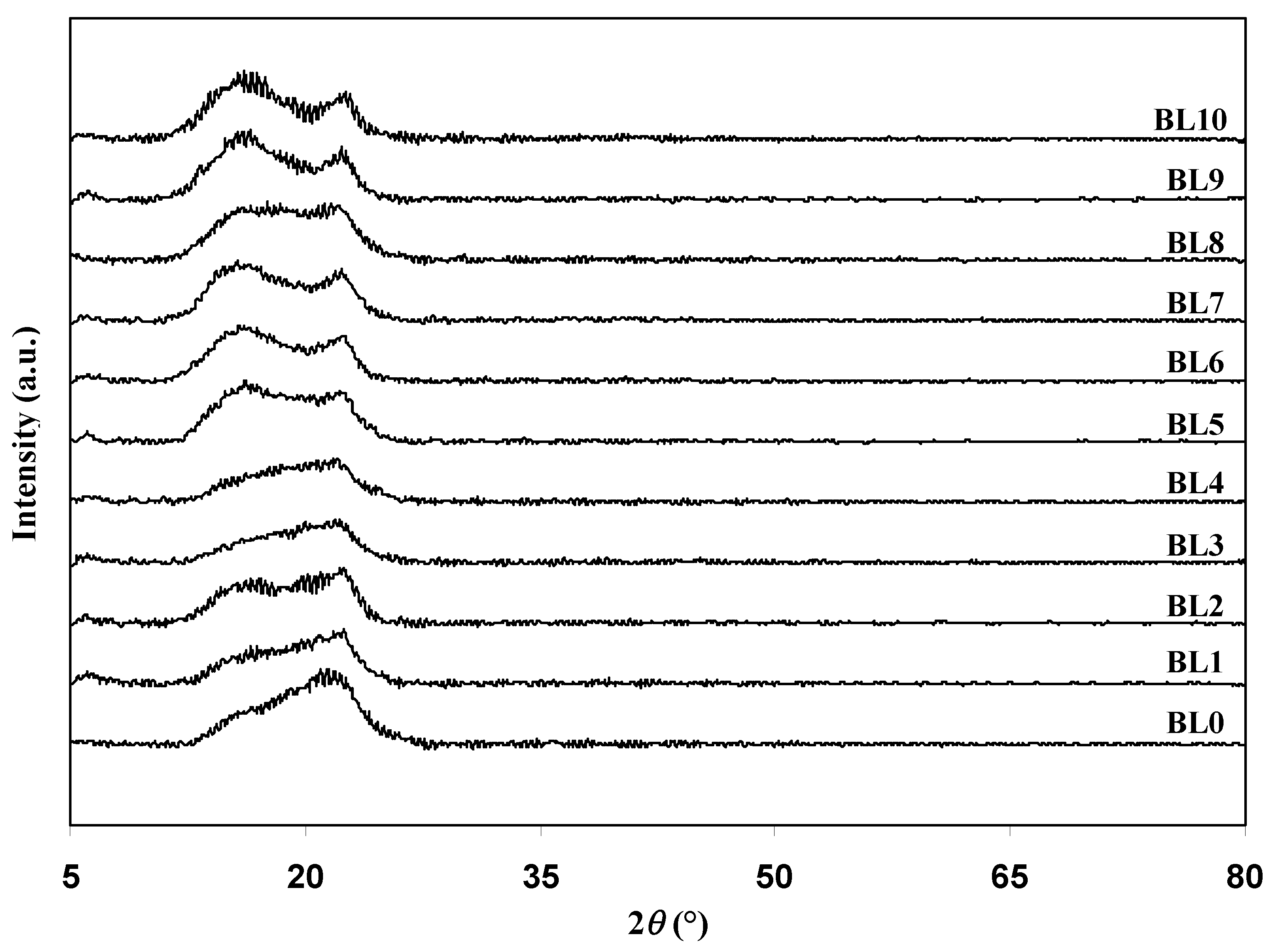
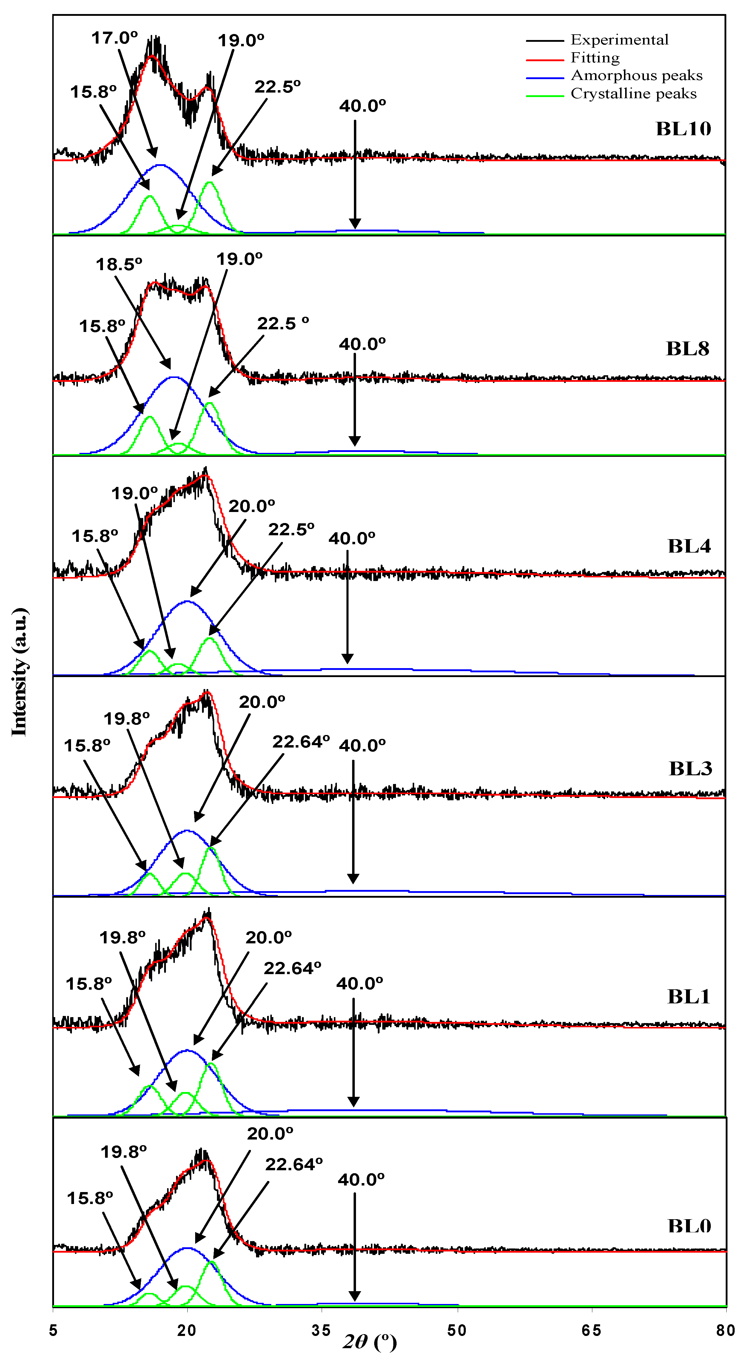
3.1. Ideal Composition for the Polymer Blend Host of the Electrodes Separator

Figure 1 shows the XRD patterns of the polymer blends. The pattern of the XRD for BL0 has two humps at 2θ = 15.8° and 22.64°, where the peak at 15.8° is less prominent. This is a typical XRD pattern of semi-crystalline materials. As more Dex is added into the polymer blend, these two peaks changed their intensity and position. The trend inthe XRD pattern moved towards the pattern of BL10 as more Dex was added. This indicates that the oxygen-containing functional groups of Dex and hydrogen in the structure of HEC, or vice versa, have formed an interaction via hydrogen bonding. Furthermore, it is a sign that the crystalline structure in the blend has been reduced [31]. From the plot in Figure 1, BL4 has the most negligible intensity among other blends, which signifies that BL4 has the most amorphous structure compared to the other blends. However, this statement has to be further confirmed through the deconvolution technique as it helps to separate any potential amorphous and crystalline peaks that may overlap. In this method, prominent peaks signify amorphous regions, while the narrow peaks indicate that the region is crystalline [32].
Figure 2 shows the deconvoluted XRD patterns of the chosen polymer blend films. BL0 and BL10 can serve as the references for detecting changes in the peak position or intensity in the diffractogram of the polymer blends. The XRD pattern of BL0 has three crystalline peaks at 2θ = 15.8°, 19.8°, and 22.64°, as well as two amorphous peaks at 2θ = 20.0° and 40.0°. This finding is similar to the results obtained by Hanif et al. [33]. In another study [34], for BL10, three crystalline peaks at 2θ = 15.8°, 19.0°, and 22.5° and two amorphous peaks at 2θ = 20.0° and 40.0° have similarly appeared [34]. The XRD pattern in BL4 indicates a reduction in the intensity of three crystalline peaks at 2θ = 15.8°, 19.0°, and 22.5°, indicating the increase in amorphousness of the blend. Equation (1) calculates the degree χc, and the results are tabulated in Table 3. BL4 blend has the most amorphous blend as it displays the lowest χc; therefore, the blend of 40 wt% Dex and 60 wt% HEC is chosen as the polymer host.

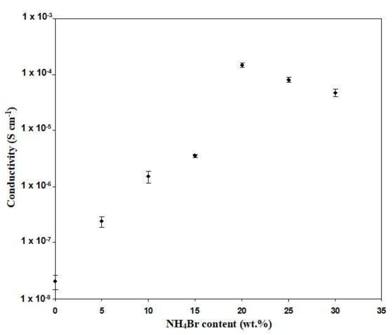
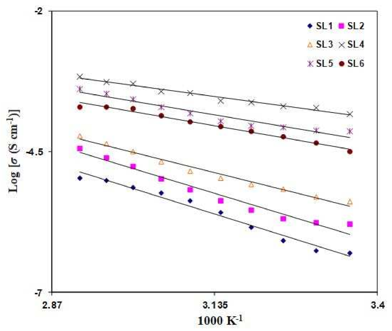
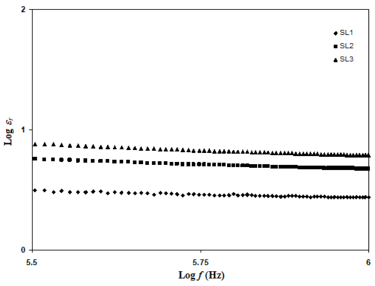
3.2. Conductivity Analysis

Figure 3 displays the variation in room temperature DC conductivity (with error bars) when the NH4Br content is changed. It is observed that the conductivity increases from (2.04 ± 0.57) × 10−8 to (2.42 ± 0.54) × 10−7 S cm−1 as 5 wt% of NH4Br is added into the Dex-HEC host. It can be seen that the conductivity value has been maximized up to (1.47 ± 0.12) × 10−4 S cm−1 with the inclusion of 20 wt% NH4Br into the polymer host. This inclination in the conductivity value is a result of the increment in the charge carrier [24]. However, the trend stops at 20 wt% NH4Br content. Any increment surpassing the 20 wt% of NH4Br content leads to a decreasing conductivity value. This finding was verified by Mohamed et al. [35], who concluded that the reduction in conductivity value is due to ion pairs, ion triplets, and higher ion aggregations, which significantly reduce the mobility and ionic number density. The variation in conductivity for the salted electrolytes as a function of temperature is depicted in Figure 4. Conductivity is observed to increase with the rise of the temperature. Due to the linear relation between conductivity and temperature (R2 ~ 0.97–0.99), all electrolytes in this study obey the Arrhenius law. Therefore, the polymer host structure does not have a phase transition when the salt is added [36]. The equation of Arrhenius is given as
σ = σ o exp E a c k T
where Eac is the ion activation energy for the migration from one site to another, k is the Boltzmann constants, σ o stands for a pre-exponential component, and T is the absolute temperature. Other proton-based polymer electrolyte studies have also reported Arrhenius behavior, such as PVA-NH4SCN [37], MC-PVA-NH4NO3 [38], and PVA-NH4Cl [23]. The plot slope in Figure 4 is used to evaluate Eac. As illustrated in Table 4, the Eac value is 0.68 when 5 wt% NH4Br is infused and further decreases to 0.26 with the presence of 20 wt% NH4Br. Sohaimy et al. [39] reported that the highest conducting electrolyte, carboxymethylcellulose (CMC) doped with ammonium carbonate ((NH4)2CO3), has the lowest Eac value. The number density of ions in the electrolyte increases as the NH4Br concentration rises, reducing the energy barrier [40]. As a result, the increased conductivity value is explained. In the transport section, the rise in conductivity with rising temperature will be discussed further.

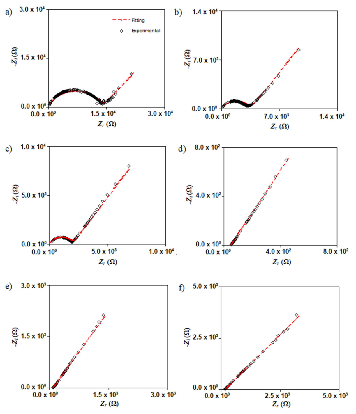
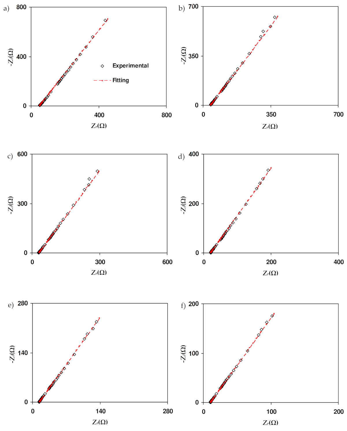
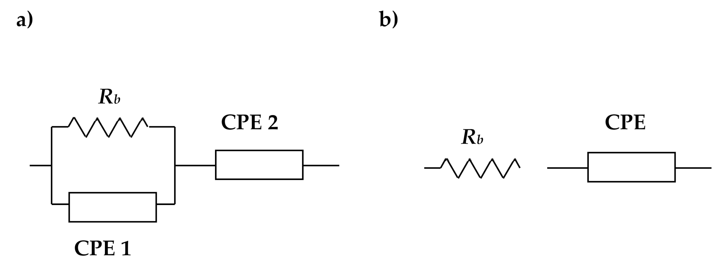
3.3. Impedance Analysis

Figure 5 displays the Nyquist plot for SL1, SL2, SL3, SL4, SL5, and SL6 at room temperature. SL1 (Figure 5a) shows a semicircle and spike. Rb can be obtained from the interception of the semicircle and spike. Ionic migration in the bulk of electrolytes caused the shape of the semicircle at higher frequencies while the spike at low frequencies indicates a polarization effect [41]. As the concentration of salt increases, theSL2 and SL3 semicircles decreased; this denotes that there are more ions available. Thus, more ions can travel from one electrode to the other, as the concentration of NH4Br increases [42]. As seen in Figure 5d, the addition of 20 wt% NH4Br (SL4) resulted in the disappearance of the semicircle. Compared with the previous SL1, Rb is taken from the intersection point of the spike and horizontal axis. Shukur [43] stated that the disappearance of the semicircle is due to the dominance of resistive parts of the polymer. This condition also suggests that there is an increment in the number density of ions. The Rb value for SL5 and SL6 increase, implying that the salt was recrystallized [44]. This means that the conductivity value of SL5 and SL6 is lower than SL4. The SL4 electrolyte is selected for impedance analysis at different temperatures, as shown in Figure 6. The increment in temperature leads to a decrease in the Rb value. The temperature enhances the salt dissociation and the segmental movement of the polymer as well [45]. Hence, the electrolyte conductivity will be increased as the temperature rises.
The equivalent electrical circuit is used because it gives an easy and direct picture of the device. Figure 7a,b shows the corresponding circuit for the semicircle-spike and spike plots, respectively. Due to the electrolyte’s inhomogeneity, it was categorized as an “imperfect capacitor”, known as the constant-phase element (CPE). CPE is given as [46]
Z C P E = 1 C ω p cos π p 2 i sin π p 2
where p relates to the plot’s deviation from the axis. Zi and Zr are the imaginary and real parts of the impedance, respectively. C is the CPE’s capacitance, while ω is the radial frequency. The circuit in Figure 7a (for the spike and semicircle) can be expressed via the following equations:
Z r = R b C 1 ω p 1 cos π p 1 2 + R b 2 R b C 1 ω p cos π p 2 + R b 2 C 2 ω 2 p + 1 + cos π p 2 2 C 2 ω p 2
Z i = R b C 1 ω p 1 sin π p 1 2 2 R b C 1 ω p cos π p 2 + R b 2 C 2 ω 2 p + 1 + sin π p 2 2 C 2 ω p 2
where p2 is the spike deviation from the horizontal axis and p1 is the spike deviation from the vertical axis for semicircle deviation. C1 and C2 are related to the high- and low-frequency capacitance, respectively. As shown in Figure 7b, the impedance plot with a spike has a circuit of series combination between Rb and CPE. This set of impedance can be expressed in these equations:
Z r = cos π p 2 C ω p + R b
Z i = sin π p 2 C ω p
The circuit elements for salted electrolytes with various circuit element parameters have been determined and are shown in Table 5 and Table 6. Based on Table 5, the C value is higher at a low frequency than at a high frequency. This phenomenon is consistent with the following equation:
C = A ε o ε r d
In this equation, εr and εo stand for the dielectric constant and vacuum permittivity, respectively. The value of εr is low at a high frequency, which, successively, gives a low value of C [47]. Dielectric information will be further explained in the dielectric section. It is observed that the value of C increases as more salt is incorporated. The high value of C indicates that more ions are produced at a high concentration of salt. Table 6 shows the circuit element of SL4 at 298, 303, 313, 323, 333, and 343 K, respectively. The increase in C at a higher temperature is due to the enhancement of mobile ions at a high temperature. Shuhaimi et al. [48] stated that the rise in C value with increasing temperature means that the electrolyte is suitable for the implementation in technologies of electrochemical devices.

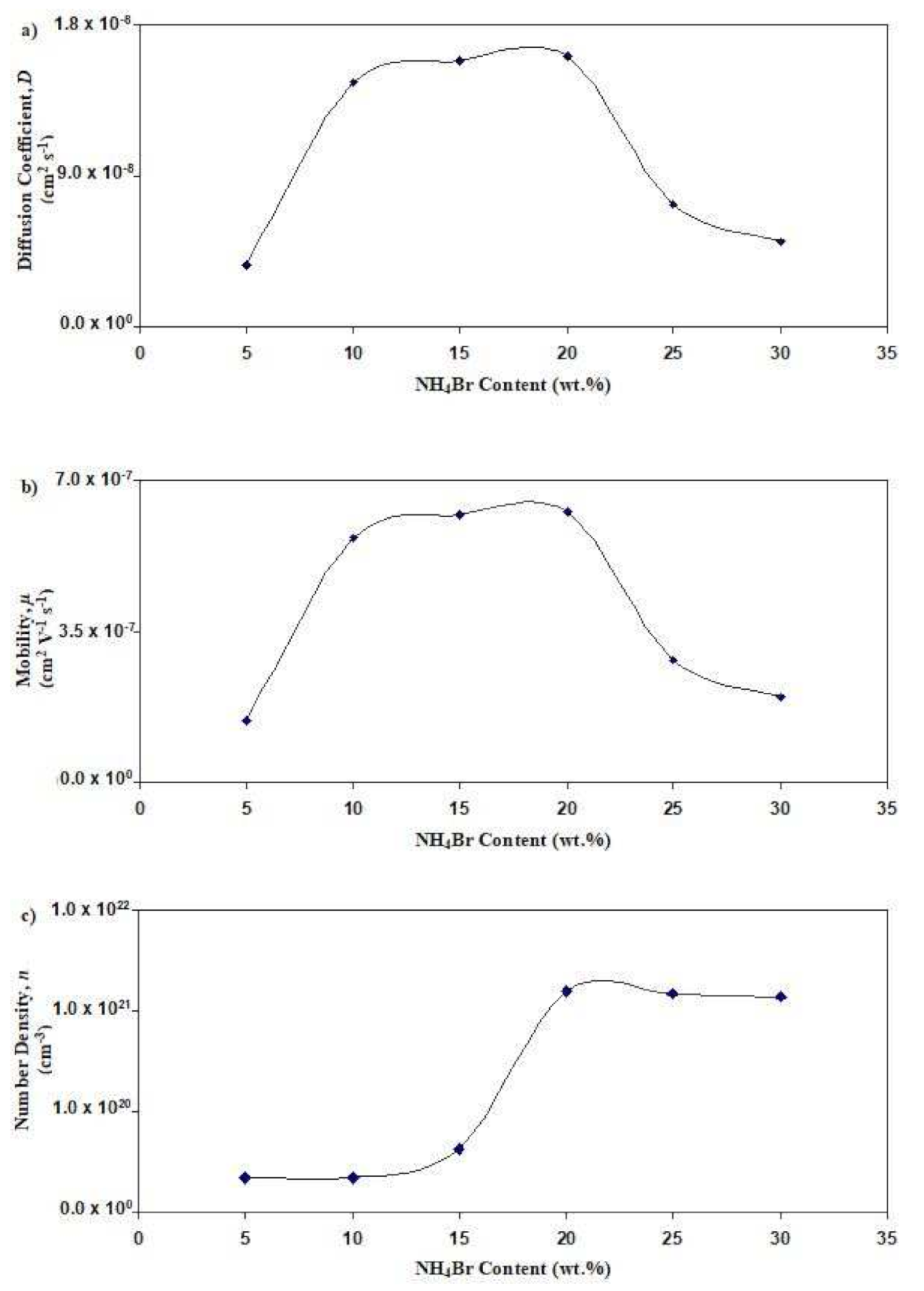
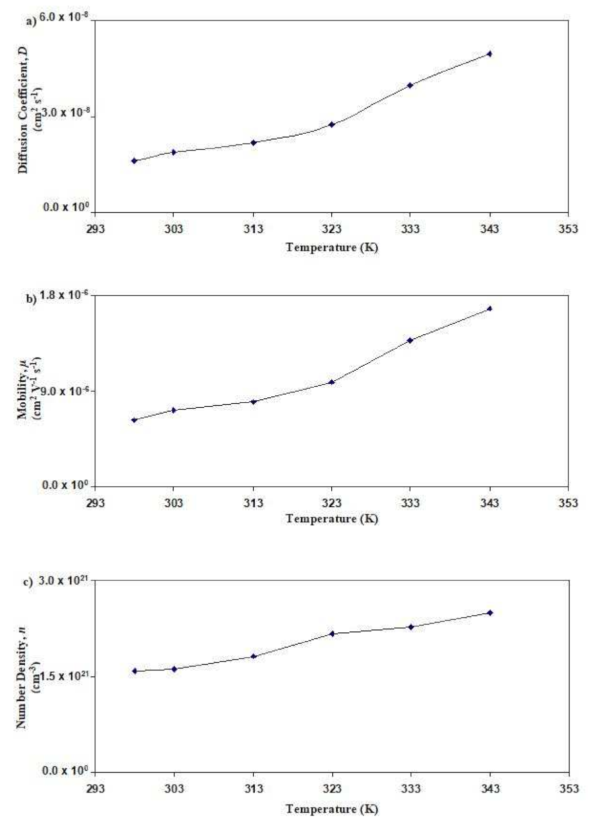
3.4. Determination of Transport Parameters

Transport analysis is a pivotal study as it identifies the value of the mobility (μ) of ions and the number density (n). The conductivity value is affected by these two parameters, n and μ, as shown in the following equation:
σ = n e μ
where e is the electronic charge. The Arof-Noor (A-N) method is used to study the transport properties of electrolytes [49]. By utilizing the A-N method, it enables us to determine the transport properties of impedance analysis. The μ value is expressed as:
μ = e D k T
where the coefficient of diffusion (D) for impedance plots with a combination of a semicircle and spike can be described as
D = A k 2 ε r ε o 2 τ 2
Here, k2 can be extracted from the impedance where k2 is inverse to C2, and τ2 is taken from the Zi minimum. Fadzallah et al. [50] stated that the value of εr can be determined where log εr is constant. For impedance plots with a spike only, the value of D can be determined from
D = D o exp 0.0297 ln D o 2 1.4348 ln D o 14.504
D o = 4 k 4 d 2 × R b 4 ω m 3 1
where ωm stands for angular frequency associated with the minimum Zi, while k is the inverse of C of the impedance fitting. In Figure 5, the Nyquist plot of SL1, SL2, and SL3 consists of a semi-circle and an inclined spike. Equation (12) is therefore used to calculate the value of D. According to Equation (12), by plotting the log εr vs. log f, the constant value of εr can be determined. Based on Figure 8, εr is obtained by log εr > 5.5.
Figure 9 displays the salted electrolyte’s transport parameters at room temperature. In Figure 9a, the concentration of NH4Br increases from 5 wt% to 20 wt%; it is observed that the value of D increases from 3.65 × 10⁻⁹ cm2 s−1 to 1.61 × 10⁻⁸ cm2 s−1, respectively. However, when 25 wt% and 30 wt% of NH4Brare added, the value of D drops to 7.26 × 10⁻⁹ cm2 s−1 and 5.02 × 10⁻⁹ cm2 s−1, respectively. A similar pattern is observed for μ as displayed in Figure 9b, as the most conductive salted electrolyte (with 20 wt% NH4Br) has the highest value of μ (6.27 × 10⁻⁷ cm2 V−1 s−1). In Figure 9c, it is observed that the value of n at 20 wt% NH4Br achieved the maximum value of 1.58 × 1021 cm−3. The n value decreases as the concentration of NH4Br reaches 25 wt%. This shows that the ionic conductivity trend at room temperature for the salted electrolyte is aligned with the trend of D, μ, and n. Hence, it can be concluded that the decrement of the transport parameters at a high salt content is relatively caused by the close distance between the cations and anions, which leads to the reduction in the number density of the ion and ionic conductivity [51]. Figure 10 displays the transport parameters for SL4 at various temperatures. Figure 10a shows that the D value increases from 1.61 × 10⁻⁸ cm2 s−1 to 4.97 × 10⁻⁸ cm2 s−1 as the temperature increases from 298 K to 343 K. The same pattern for μ is obtained, whose maximum value is observed in Figure 10b at 1.68 × 10⁻⁶ cm2 V−1 s−1. It is visible from Figure 10c that the value of n increases from 1.58 × 1021 cm−3 to 2.51 × 1021 cm−3. This segment of polymers vibrates at high temperatures, resulting in free volume enhancement. This volume allows ion pairs to dissociate and form free ions that indirectly increase the diffusivity and mobility of ions.

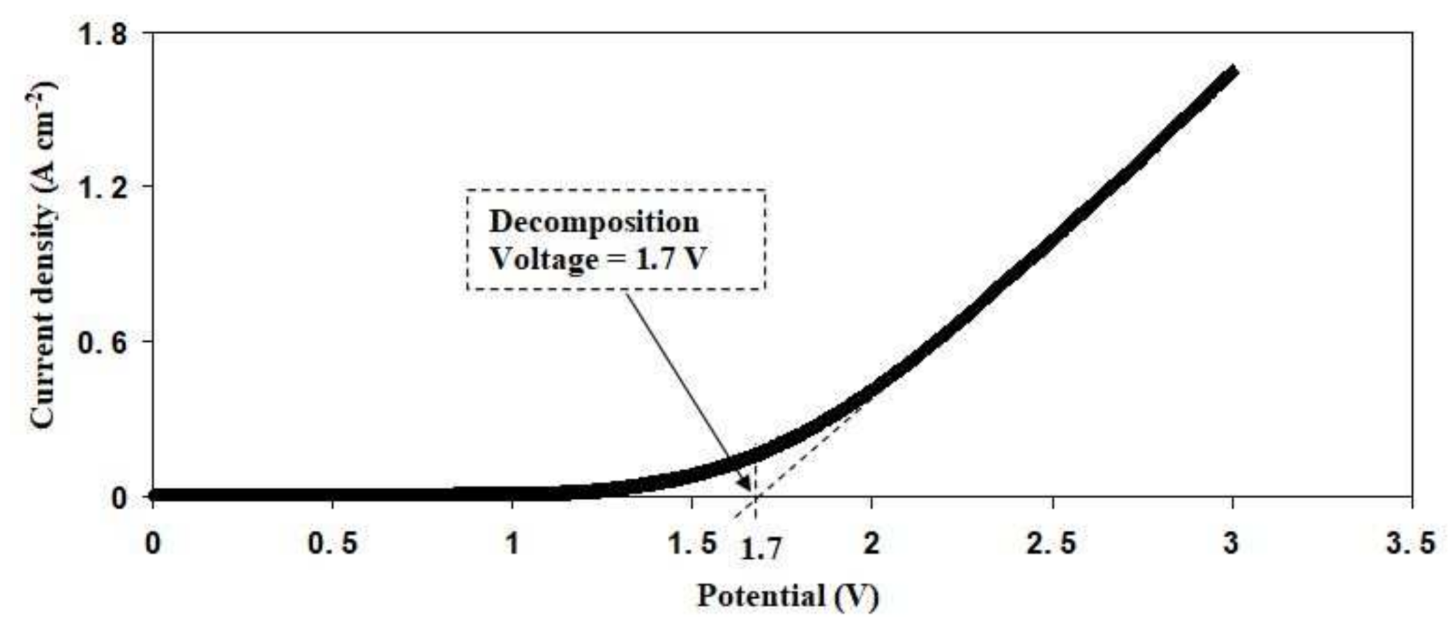
3.5. Linear Sweep Voltammetry (LSV)

A linear sweep voltammetry (LSV) study is an essential tool used to check the suitability of the electrolyte in electrochemical device applications. Figure 11 displays the LSV plot for SL4. There are no apparent changes in the current value at a potential less than 1.7 V as the potentials are swept linearly from 0 to 3 V. This means that SL4 is electrochemically stable up to 1.7 V [52]. The increase in current over 1.7 V is due to the electrolyte decomposition at the surface of the inert electrode [53]. Aziz et al. [54] reported an ammonium salt-based biopolymer electrolyte, where it started to decompose at 1.27 V. This finding is very similar to other polymer electrolytes with an ammonium salt. Electrochemical stability up to 1.6 V has been reported by Noor and Isa [55] for a polymer electrolyte system of CMC doped with NH4SCN. The CS-NH4I-Zn-glycerol system is reported to be potentially stable up to 1.37 V [53]. As a consequence of this finding, it can be stated that the highest conducting electrolyte provides sufficient potential stability for the use of energy storage devices.

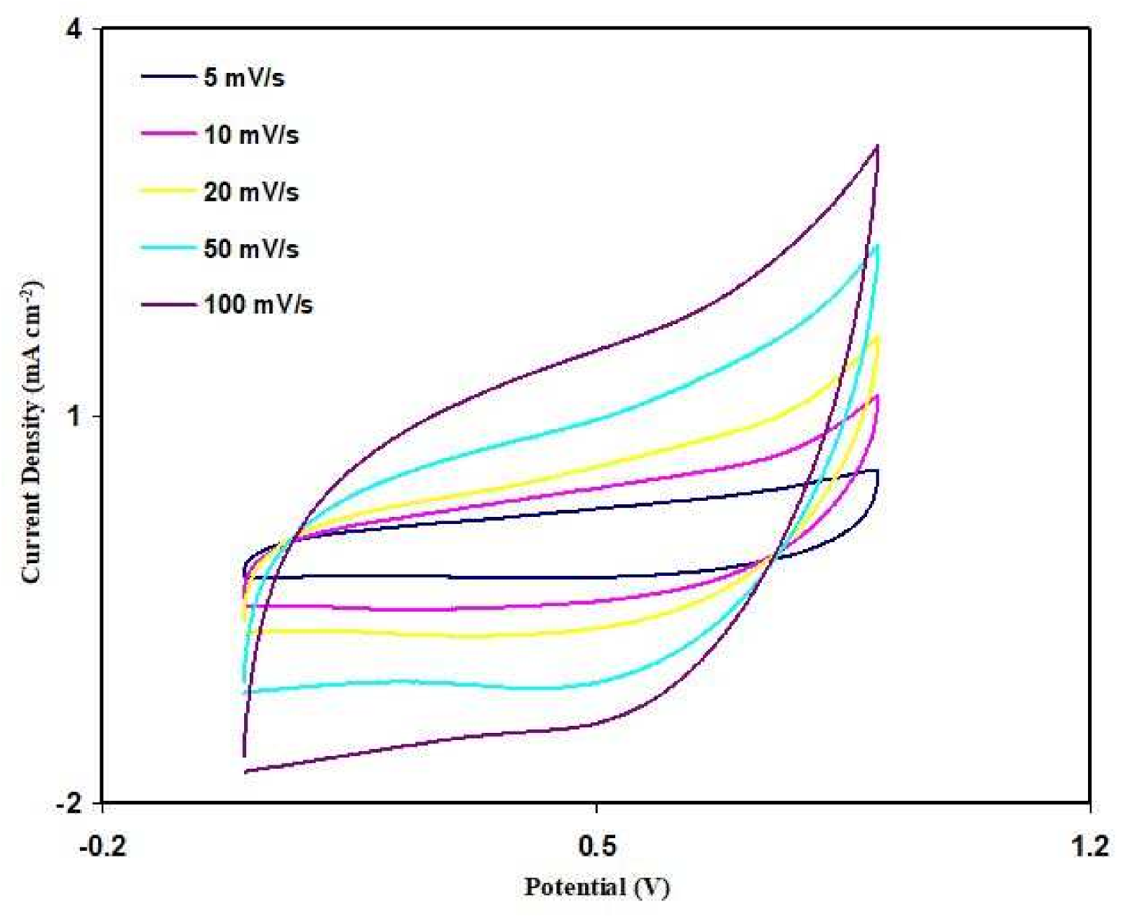
3.6. Cyclic Voltammetry (CV)

Cyclic voltammetry (CV) analysis has been used to test the EDLC fabricated using SL4. The CV curve for the fabricated EDLC is shown in Figure 12 at a series of scan rates. It is observed that redox reactions do not occur in the potential range between 0 and 0.9 V, as the peaks that indicate that situation is absent. This situation tallies with the energy storage mechanism of an EDLC [56]. It is noticeable that as the scan rate decreases, the CV shape shifts from a leaf shape to nearly a rectangular shape. Kant et al. [57] mentioned that the rectangular CV curve indicates a good charge transport. The specific capacitance (CCV) of the EDLC can be obtained from the CV curve using the following equation:
C C V = V i V f I ( V ) d V 2 m a ( V f V i )
where the area of the CV curve (∫I(V)dV)in cm2 is extracted using the integration feature of Origin 8.5 software. The scan rate in V/s is represented by a, while the mass of the activated material with gram (g) is represented by m. Vf, and Vi, respectively, representing the final voltage of 0.9 V and the initial voltage of 0 V. Table 7 shows the calculated values of CCV. As the scan rate decreases, the CCV value increases. Ions can form proper Helmholtz layers at the surface of activated carbon electrodes at low scan rates. At higher scan rates, some ions undergo recombination and the transportation of ions is unstable, thus providing a low capacitance value [58,59].

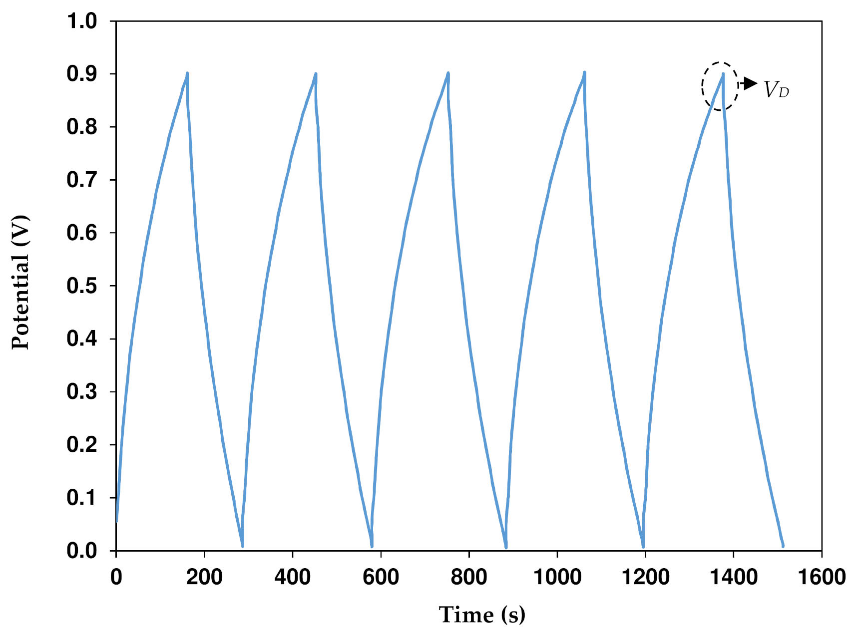
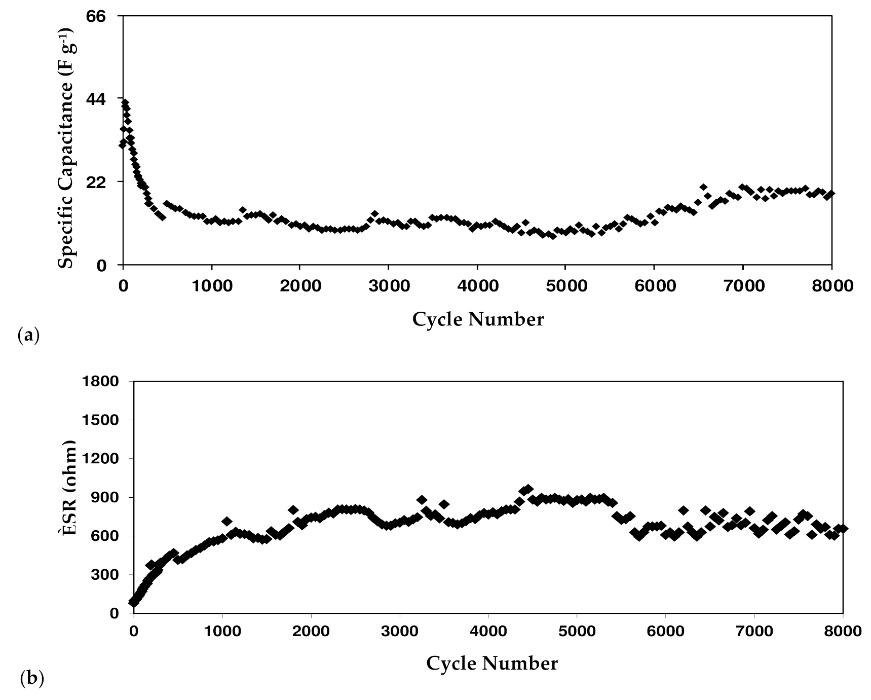
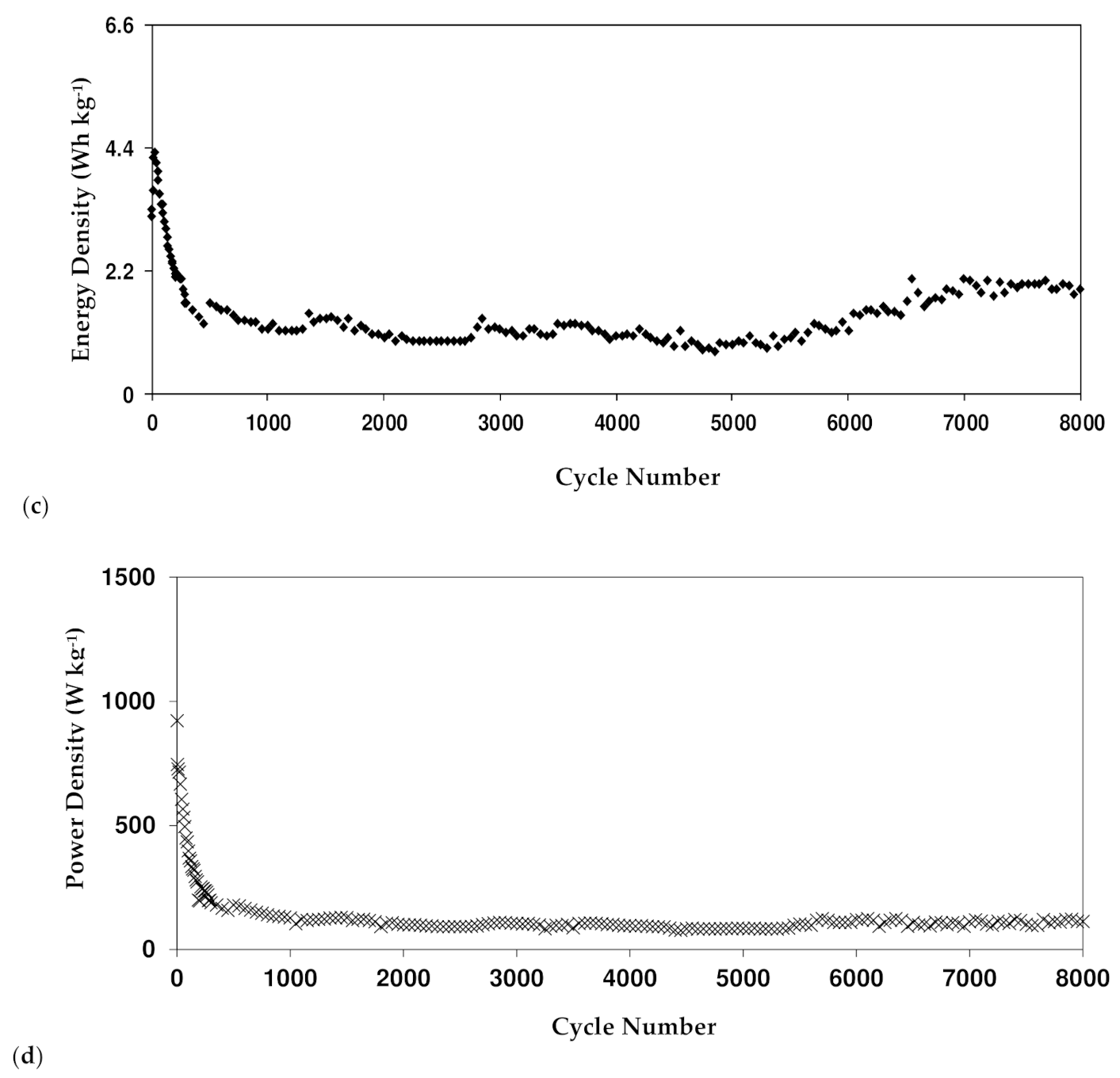
3.7. Dex-HEC-NH4Br-Based EDLC

At 0.25 mA cm−2 and a potential range of 0 to 0.9 V, the EDLC’s rechargeability is tested for 8000 cycles. Figure 13 shows the EDLC’s charge-discharge plot. The EDLC’s capacitive behavior can be seen by the discharge slope, which is nearly linear [60]. Since the slope of the discharge curve (s) is known, the specific capacitance (CCD) can be calculated using the following equation:
C C D = i s m
where i is the constant current. Figure 14a shows the CCD of the EDLC where the 1st cycle is 31.7 F g−1. This value is comparable to the one obtained from CV analysis. The CCD increases to 42.8 F g−1 as the cycle number reaches the 30th cycle but reduces to 12.4 F g−1 until 450th cycles. Some ions are recombined in the rapid charge and discharge process creating ion pairs or aggregations. Ion pairs or aggregations block the conduction of ions, thus reducing the value of the capacitance [61]. It is common in EDLC that at the beginning cycles the performance is unstable as cations and anions are still trying to recognize the polarization pattern. The stabilization of CCD can be observed from 450th to the 8000th cycle with an average of 13.1 F g−1. Table 8 shows EDLC reported in other works with their respective parameters.
The ideal charge-discharge curve is similar to a triangular shape. However, the poor triangular shape could be due to the roughness of the carbon electrode, the type of electrolytes, and the internal resistance. As shown in Figure 13, the discharge process is started by a slight potential drop (VD). It can be linked to internal resistance in the EDLC, which is called the equivalent series resistance (RESR). Based on the following equation, we can obtain the RESR:
R E S R = V D i
Figure 14b shows the RESR of the EDLC for 8000 cycles and it varies from 80 to 880 Ω. To begin, a double-layer charge or potential energy might emerge in the gap between the electrolyte and the electrode. The presence of ions from the electrolyte and electrons from the carbon electrode results in a double-layer charge [62]. Second, it is from the electrolyte itself that the fast charge/discharge process induces recombination of free ions and reduces the ionic conductivity. Finally, it is the current collectors. In this case, it is aluminum foil.
The energy density (ED) of the EDLC can be expressed as
E D = C C D V 2
where V is the applied voltage (0.9 V). ED is found to be 3.18 Wh kg−1 in the 1st cycle in Figure 14c. The stabilization can be observed as soon as the cycle number reaches 450 where it fluctuates with an average of 1.31 Wh kg−1 up to the 8000th cycle. The pattern of ED is harmonized with the pattern of CCD. This stabilization of the ED values indicates that the ions face the same energy barrier during migration towards the electrodes from 450th to 8000th cycle. [32] Another crucial parameter of the EDLC is power density (PD) which can be determined using:
P D = V 2 4 m R E S R
As shown in Figure 14d, the value of PD is plotted up to 8000 cycles. In the 1st cycle, the value of PD is 922.22 W kg−1, but it decreases down to 319.6 W kg−1 at the 150th cycle. The PD then further reduces to 158.4 W kg−1 at the 450th cycle before it become constant at an average of 109 W kg−1. This may be linked to the electrolyte depletion and growth of ion aggregates/pairs during the quick charge-discharge process. Ion aggregates/pairs are the critical drawbacks of polymer electrolyte membranes. As a result, the accumulated ion in the double-layer formed at the surface of the electrodes is lowered and thus the power density is decreased [56].

4. Conclusions

The solid polymer electrolyte systems based on a Dex-HEC blend and doped with ammonium bromide (NH4Br) were effectively prepared viathe solution casting technique. The 40 wt% Dex-60 wt% HEC blend has the most suitable polymer host ratio. A 20 wt% NH4Br increased the conductivity to up to (1.47 ± 0.12) × 10−4 S cm−1. The number density and mobility of ions in the highest conducting electrolyte (SL4) were 1.58 × 1021 cm−3 and 6.27 × 10⁻⁷ V−1s−1 cm2, respectively. Up to 1.7V, the electrolyte is potentially stable. The EDLC’s specific capacitance and energy density were stable at 13.1 F g−1 and 1.31 Wh kg−1, respectively. Even though the EDLC has been subjected to rapid charge-discharge, there are no extreme changes in the internal resistance value. The pattern of power density is highly related to the ESR, where it becomes constant at 109 W kg−1. The performance of the EDLC at a cycle below 450 is unstable because ions in the electrolyte are still in the process of recognizing the pattern of adsorption/desorption and conduction. Thus, it can be concluded that the Dex-HEC-NH4Br-based EDLC has shown an excellent performance. A plasticizer or filler can be added to the electrolyte to enhance the ionic conductivity for future improvement. The procedure and materials used in electrode fabrication can be modified to enhance the EDLC’s performance.

Author Contributions

Conceptualization, S.B.A., M.F.Z.K. and M.S.; Data curation, Z.I.Z. and Z.M.E.-B.; Formal analysis, E.M.A.D.; Funding acquisition, E.M.A.D. and M.M.N.; Investigation, M.A.S.A.; Methodology, M.A.S.A.; Project administration, S.B.A., M.F.Z.K., Z.I.Z. and M.S.; Supervision, M.F.Z.K. and M.S.; Validation, E.M.A.D., M.F.Z.K., Z.I.Z., Z.M.E.-B. and M.M.N.; Writing—original draft, M.A.S.A.; Writing—review & editing, S.B.A., M.F.Z.K., Z.I.Z., Z.M.E.-B., M.S. and M.M.N. All authors have read and agreed to the published version of the manuscript.

Funding

This research was funded by VOCO GmbH, grant number BGAAF-1683.

Institutional Review Board Statement

Not applicable.

Informed Consent Statement

Not applicable.

Data Availability Statement

Data is contained within the article.

Acknowledgments

The authors would like to thank the University of Malaya for the facilities provided and grant Fundamental Research Grant Scheme (FP039-2019A). This work was financially supported by the Taif Researchers Supporting Project (TURSP-2020/42), Taif University, Taif, Saudi Arabia. We would like to acknowledge all support for this work by the University of Sulaimani, University of Malaya and Komar University of Science and Technology.

Conflicts of Interest

The authors declare no conflict of interest.

References

  1. Iqbal, M.Z.; Rafiuddin, S. Structural, electrical conductivity and dielectric behavior of Na2SO4–LDT composite solid electrolyte. J. Adv. Res. 2016, 7, 135–141. [Google Scholar] [CrossRef] [Green Version]
  2. Tomboc, G.M.; Kim, H. Derivation of both EDLC and pseudocapacitance characteristics based on synergistic mixture of NiCo2O4 and hollow carbon nanofiber: An efficient electrode towards high energy density supercapacitor. Electrochim. Acta 2019, 318, 392–404. [Google Scholar] [CrossRef]
  3. Amran, N.N.A.; Manan, N.S.A.; Kadir, M.F.Z. The effect of LiCF3SO3 on the complexation with potato starch-chitosan blend polymer electrolytes. Ionics 2016, 22, 1647–1658. [Google Scholar] [CrossRef]
  4. Arya, A.; Sharma, A.L. Polymer electrolytes for lithium ion batteries: A critical study. Ionics 2017, 23, 497–540. [Google Scholar] [CrossRef]
  5. Salleh, N.S.; Aziz, S.B.; Aspanut, Z.; Kadir, M.F.Z. Electrical impedance and conduction mechanism analysis of biopolymer electrolytes based on methyl cellulose doped with ammonium iodide. Ionics 2016, 22, 2157–2216. [Google Scholar] [CrossRef]
  6. Li, H.; Han, C.; Huang, Y.; Huang, Y.; Zhu, M.; Pei, Z.; Zhi, C. An extremely safe and wearable solid-state zinc ion battery based on a hierarchical structured polymer electrolyte. Energy Environ. Sci. 2018, 11, 941–951. [Google Scholar] [CrossRef]
  7. Du, B.W.; Hu, S.Y.; Singh, R.; Tsai, T.T.; Lin, C.C.; Ko, F.U. Eco-friendly and biodegradable biopolymer chitosan/Y2O3 composite materials in flexible organic thin-film transistors. Materials 2017, 10, 1026. [Google Scholar] [CrossRef] [PubMed] [Green Version]
  8. Azli, A.A.; Manan, N.S.A.; Kadir, M.F.Z. The development of Li+ conducting polymer electrolyte based on potato starch/graphene oxide blend. Ionics 2017, 23, 411–425. [Google Scholar] [CrossRef]
  9. Yusof, Y.M.; Illias, H.A.; Shukur, M.F.; Kadir, M.F.Z. Characterization of starch-chitosan blend-based electrolyte doped with ammonium iodide for application in proton batteries. Ionics 2017, 23, 681–697. [Google Scholar] [CrossRef]
  10. Chong, M.Y.; Numan, A.; Liew, C.-W.; Ramesh, K.; Ramesh, S. Comparison of the performance of copper oxide and yttrium oxide nanoparticle based hydroxylethyl cellulose electrolytes for supercapacitors. J. Appl. Polym. Sci. 2017, 134, 44636. [Google Scholar] [CrossRef]
  11. Zhang, M.Y.; Li, M.X.; Chang, Z.; Wang, Y.F.; Gao, J.; Zhu, Y.S.; Wu, Y.P.; Huang, W. A sandwich PVDF/HEC/PVDF gel polymer electrolyte for lithium ion battery. Electrochim. Acta 2017, 245, 752–759. [Google Scholar] [CrossRef]
  12. Li, M.X.; Wang, X.W.; Yang, Y.Q.; Chang, Z.; Wu, Y.P.; Holze, R. A dense cellulose-based membrane as a renewable host for gel polymer electrolyte of lithium ion batteries. J. Membr. Sci. 2015, 476, 112–118. [Google Scholar] [CrossRef]
  13. Selvanathan, V.; Halim, M.N.A.; Azzahari, A.D.; Rizwan, M.; Shahabudin, N.; Yahya, R. Effect of polar aprotic solvents on hydroxyethyl cellulose-based gel polymer electrolyte. Ionics 2018, 24, 1955–1964. [Google Scholar] [CrossRef]
  14. Tiwari, S.; Patil, R.; Bahadur, P. Polysaccharide based scaffolds for soft tissue engineering applications. Polymers 2019, 11, 1. [Google Scholar] [CrossRef] [Green Version]
  15. Sirisha, V.L.; Souza, J.; Kim, S.-K. Marine OMICS: Principles and Applications; Marine Foodomics; CRC Press: Boca Raton, FL, USA, 2016; pp. 643–682. [Google Scholar]
  16. Netsopa, S.; Niamsanit, S.; Sakloetsakun, D.; Milintawisamai, D. Characterization and rheological behavior of dextran from weissellaconfusa R003. Int. J. Polym. Sci. 2018, 2018, 1–10. [Google Scholar] [CrossRef] [Green Version]
  17. Aziz, S.B.; Hadi, J.M.; Elham, E.M.; Abdulwahid, R.T.; Saeed, S.R.; Marf, A.S.; Karim, W.O.; Kadir, M.F.Z. The study of plasticized amorphous biopolymer blend electrolytes based on polyvinyl alcohol (PVA): Chitosan with high ion conductivity for energy storage electrical double-layer capacitors (EDLC) device application. Polymers 2020, 12, 1938. [Google Scholar] [CrossRef]
  18. Rajendran, S.; Mahendran, O. Experimental investigations on plasticized PMMA/PVA polymer blend electrolytes. Ionics 2001, 7, 463–468. [Google Scholar] [CrossRef]
  19. Shukur, M.F.; Kadir, M.F.Z. Electrical and transport properties of NH4Br-doped cornstarch-based solid biopolymer electrolyte. Ionics 2015, 21, 111–124. [Google Scholar] [CrossRef]
  20. Shukur, M.F.; Majid, N.A.; Ithnin, R.; Kadir, M.F.Z. Effect of plasticization on the conductivity and dielectric properties of starch-chitosan blend biopolymer electrolytes infused with NH4Br. Phys. Scr. 2013, 57, 014051–014057. [Google Scholar] [CrossRef]
  21. Nayak, R.; Dey, T.; Ghosh, P.; Bhattacharyya, A.R. Phosphoric acid doped poly(2,5-benzimidazole)-based proton exchange membrane for high temperature fuel cell application. J. Polym. Eng. Sci. 2016, 56, 20–25. [Google Scholar] [CrossRef]
  22. Pujiastuti, S.; Onggo, H. Effect of various concentration of sulfuric acid for Nafion membrane activation on the performance of fuel cell. AIP Conf. Proc. 2016, 1711, 060006. [Google Scholar]
  23. Hemalatha, R.; Alagar, M.; Selvasekarapandian, S.; Sundaresan, B.; Moniha, V.; Boopathi, G.; Selvin, P.C. Preparation and characterization of proton-conducting polymer electrolyte based on PVA, amino acid proline, and NH4Cl and its applications to electrochemical devices. Ionics 2019, 25, 141–154. [Google Scholar] [CrossRef]
  24. Aziz, S.B.; Dannoun, E.M.A.; Hamsan, M.H.; Ghareeb, H.O.; Nofal, M.M.; Karim, W.O.; Asnawi, A.S.F.M.; Hadi, J.M.; Kadir, M.F.Z.A. A polymer blend electrolyte based on cs with enhanced ion transport and electrochemical properties for electrical double layer capacitor applications. Polymers 2021, 13, 930. [Google Scholar] [CrossRef]
  25. Vijaya, N.; Selvasekarapandian, S.; Hirankumar, G.; Karthikeyan, S.; Nithya, H.; Ramya, C.S.; Prabu, M. Structural, vibrational, thermal, and conductivity studies on proton-conducting polymer electrolyte based on poly (N-vinylpyrrolidone). Ionics 2012, 18, 91. [Google Scholar] [CrossRef]
  26. Hafiza, M.N.; Bashirah, A.N.A.; Bakar, N.Y.; Isa, M.I.N. Electrical properties of carboxyl methylcellulose/chitosan dual-blend green polymer doped with ammonium bromide. Int. J. Polym. Anal. Charact. 2014, 19, 151–158. [Google Scholar] [CrossRef]
  27. Hamsan, M.H.; Shukur, M.F.; Aziz, S.B.; Kadir, M.F.Z. Dextran from Leuconostocmesenteroides-doped ammonium salt-based green polymer electrolyte. Bull. Mater. Sci. 2019, 42, 57. [Google Scholar] [CrossRef] [Green Version]
  28. Samsudin, A.S.; Isa, M.I.N. Structural and ionic transport study on CMC doped NH4Br: A new types of biopolymer electrolytes. J. Appl. Sci. 2012, 12, 174–179. [Google Scholar] [CrossRef]
  29. Aziz, S.B.; Dannou, E.M.A.; Hamsan, M.H.; Abdulwahid, R.T.; Mishra, K.; Nofal, M.M.; Kadir, M.F.Z. Improving EDLC Device Performance Constructed from Plasticized Magnesium Ion Conducting Chitosan Based Polymer Electrolytes via Metal Complex Dispersion. Membranes 2021, 11, 289. [Google Scholar] [CrossRef]
  30. Hadi, J.M.; Aziz, S.B.; Mustafa, M.S.; Hamsan, M.H.; Abdulwahid, R.T.; Kadir, M.F.Z.; Ghareeb, H.O. Role of nano-capacitor on dielectric constant enhancement in PEO:NH4SCN:xCeO2 polymer nano-composites: Electrical and electrochemical properties. J. Mater. Res. Technol. 2020, 9, 9283–9294. [Google Scholar] [CrossRef]
  31. Marf, A.S.; Aziz, S.B.; Abdullah, R.M. Plasticized H+ ion-conducting PVA:CS-based polymer blend electrolytes for energy storage EDLC application. J. Mater. Sci. Mater. Electron. 2020, 31, 18554–18568. [Google Scholar] [CrossRef]
  32. Hamsan, M.H.; Nofal, M.M.; Aziz, S.B.; Brza, M.A.; Dannou, E.M.A.; Murad, A.R.; Kadir, M.F.Z.; Muzakir, S.K. Plasticized Polymer Blend Electrolyte Based on Chitosan for Energy Storage Application: Structural, Circuit Modeling, Morphological and Electrochemical Properties. Polymer 2021, 13, 1233. [Google Scholar] [CrossRef]
  33. Hanif, M.P.M.; Jalilah, A.J.; Badrul, F.; Nuraqmar, S.M.S. The influence of graphite on conductivity, crystallinity and tensile properties of hydroxyethyl cellulose (hec)/graphite composite films. IOP Conf. Ser. Mater. Sci. Eng. 2019, 701, 012015. [Google Scholar] [CrossRef]
  34. Li, R.; Zhang, H.; Hu, X.; Gan, W.; Li, Q. An efficiently sustainable dextran-based flocculant: Synthesis, characterization and flocculation. Chemosphere 2016, 159, 342–450. [Google Scholar] [CrossRef]
  35. Mohamed, A.S.; Shukur, M.F.; Kadir, M.F.Z.; Yusof, Y.M. Ion conduction in chitosan-starch blend based polymer electrolyte with ammonium thiocyanate as charge provider. J. Polym. Res. 2020, 27, 149. [Google Scholar] [CrossRef]
  36. Ahmed, H.T.; Abdullah, O.G. Structural and ionic conductivity characterization of PEO: MC-NH4I proton-conducting polymer blend electrolytes based films. Results Phys. 2020, 16, 102861. [Google Scholar] [CrossRef]
  37. Pandi, D.V.; Selvasekarapandian, S.; Bhuvaneswari, R.; Premalatha, M.; Monisha, S.; Arunkumar, D.; Junichi, K. Development and characterization of proton conducting polymer electrolyte based on PVA, amino acid glycine and NH4SCN. Solid State Ion. 2016, 298, 15–22. [Google Scholar] [CrossRef]
  38. Abdullah, O.G.; Aziz, S.B.; Rasheed, M.A. Incorporation of NH4NO3 into MC-PVA blend-based polymer to prepare proton-conducting polymer electrolyte films. Ionics 2018, 24, 777–785. [Google Scholar] [CrossRef]
  39. Sohaimy, M.I.H.; Isa, M.I.N. Ionic conductivity and conduction mechanism studies on cellulose based solid polymer electrolytes doped with ammonium carbonate. Polym. Bull. 2017, 74, 1371–1386. [Google Scholar] [CrossRef]
  40. Mazuki, N.; Majeed, A.P.P.A.; Samsudin, A.S. Study on electrochemical properties of CMC-PVA doped NH4Br based solid polymer electrolytes system as application for EDLC. J. Polym. Res. 2020, 27, 135. [Google Scholar] [CrossRef]
  41. Samsudin, A.S.; Khairul, W.M.; Isa, M.I.N. Characterization on potential of carboxy methylcellulose for application as proton conducting biopolymer electrolytes. J. Non-Cryst. Solids 2012, 358, 1104–1112. [Google Scholar] [CrossRef]
  42. Kartha, S.A. A Preparation of B2O3-Li2O-MO (M=Pb, Zn) Glass Thin Films and Study of Thin Properties. Ph.D. Thesis, Mahatma Gandhi University, Kerala, India, 2013. [Google Scholar]
  43. Shukur, M.F. Characterization of Ion Conducting Solid Bio-Polymer Electrolytes Based on Starch-Chitosan Blend and Application in Electrochemical Devices. Ph.D. Thesis, University of Malaya, Kuala Lumpur, Malaysia, 2015. [Google Scholar]
  44. Yulianti, E.; Deswita, D.; Sudaryanto, S.; Mashadi, S. Study of solid polymer electrolyte based on biodegradable polymer polycaprolactone. Mal. J. Fund. Appl. Sci. 2019, 15, 467–471. [Google Scholar]
  45. Yao, P.; Yu, P.; Ding, Z.; Liu, Y.; Lu, J.; Lavorgna, M.; Wu, J.; Liu, X. Review on polymer-based composite electrolytes for lithium batteries. Front. Chem. 2019, 7, 1–17. [Google Scholar] [CrossRef] [PubMed] [Green Version]
  46. Qian, X.; Gu, N.; Cheng, Z.; Yang, X.; Wang, E.; Dong, S. Impedance study of (PEO)10LiClO4-Al2O3 composite polymer electrolyte with blocking electrodes. Electrochim. Acta 2001, 46, 1829–1836. [Google Scholar] [CrossRef]
  47. Kumar, M.S.; Rao, M.C. Effect of Al2O3 on structural and dielectric properties of PVP-CH3COONa based solid polymer electrolyte films for energy storage devices. Heliyon 2019, 5, 1–10. [Google Scholar] [CrossRef] [PubMed] [Green Version]
  48. Shuhaimi, N.E.A.; Teo, L.P.; Woo, H.J.; Majid, S.R.; Arof, A.K. Electrical double-layer capacitors with plasticized polymer electrolyte based on methyl cellulose. Polym. Bull. 2012, 69, 807–826. [Google Scholar] [CrossRef]
  49. Arof, A.K.; Amirudin, S.; Yusof, S.Z.; Noor, I.M. A method based on impedance spectroscopy to determine transport properties of polymer electrolytes. Phys. Chem. 2014, 16, 1856–1867. [Google Scholar] [CrossRef] [PubMed] [Green Version]
  50. Fadzallah, I.A.; Noor, I.M.; Careem, M.A.; Arof, A.K. Investigation of transport properties of chitosan-based electrolytes utilizing impedance spectroscopy. Ionics 2016, 22, 1635–1645. [Google Scholar] [CrossRef]
  51. Ahmad, N.H.; Isa, M.I.N. Proton conducting solid polymer electrolytes based carboxymethyl cellulose doped ammonium chloride: Ionic conductivity and transport studies. Int. J. Plast. Technol. 2015, 19, 47–55. [Google Scholar] [CrossRef]
  52. Hamsan, M.H.; Shukur, M.F.; Aziz, S.B.; Yusof, Y.M.; Kadir, M.F.Z. Influence of NH4Br as an ionic source on the structural/electrical properties of dextran-based biopolymer electrolytes and EDLC application. Bull. Mater. Sci. 2020, 43, 30. [Google Scholar] [CrossRef]
  53. Hadi, J.M.; Aziz, S.B.; Saeed, S.R.; Brza, M.A.; Abdulwahid, R.T.; Hamsan, M.H.; Abdullah, R.M.; Kadir, M.F.Z.; Muzakir, S.K. Investigation of ion transport parameters and electrochemical performance of plasticized biocompatible chitosan-based proton conducting polymer composite electrolytes. Membranes 2020, 10, 363. [Google Scholar] [CrossRef]
  54. Aziz, S.B.; Brza, M.A.; Mishra, K.; Hamsan, M.H.; Karim, W.O.; Abdullah, R.M.; Kadir, M.F.Z.; Abdulwahid, R.T. Fabrication of high performance energy storage EDLC device from proton conducting methylcellulose: Dextran polymer blend electrolytes. J. Mater. Res. Technol. 2020, 9, 1137–1150. [Google Scholar] [CrossRef]
  55. Noor, N.A.M.; Isa, M.I.N. Investigation on transport and thermal studies of solid polymer electrolyte based on carboxymethyl cellulose doped ammonium thiocyanate for potential application in electrochemical devices. Int. J. Hydrog. Energy 2019, 44, 8298–8306. [Google Scholar] [CrossRef]
  56. Liew, C.W.; Ramesh, S. Electrical, structural, thermal and electrochemical properties of corn starch-based biopolymer electrolytes. Carbohydr. Polym. 2015, 124, 222–228. [Google Scholar] [CrossRef] [PubMed]
  57. Kant, R.; Singh, M.B. Theory of the electrochemical impedance of mesostructured electrodes embedded with heterogeneous micropores. J. Phys. Chem. C 2017, 121, 7164–7174. [Google Scholar] [CrossRef]
  58. Shukur, M.F.; Hamsan, M.H.; Kadir, M.F.Z. Investigation of plasticized ionic conductor based on chitosan and ammonium bromide for EDLC application. Mater. Today Proc. 2019, 17, 490–498. [Google Scholar] [CrossRef]
  59. Aziz, S.B.; Brza, M.A.; Dannoun, E.M.A.; Hamsan, M.H.; Hadi, J.M.; Kadir, M.F.Z.; Abdulwahid, R.T. The Study of Electrical and Electrochemical Properties of Magnesium Ion Conducting CS: PVA Based Polymer Blend Electrolytes: Role of Lattice Energy of Magnesium Salts on EDLC Performance. Molecules 2020, 25, 4503. [Google Scholar] [CrossRef]
  60. Teoh, K.H.; Liew, C.W.; Ramesh, S. Electric double layer capacitor based on activated carbon electrode and biodegradable composite polymer electrolyte. Ionics 2014, 20, 251–258. [Google Scholar]
  61. Teoh, K.H.; Lim, C.S.; Liew, C.W.; Ramesh, S. Electric double-layer capacitors with corn starch-based biopolymer electrolytes incorporating silica as filler. Ionics 2015, 21, 2061–2068. [Google Scholar] [CrossRef]
  62. Arof, A.K.; Kufian, M.Z.; Syukur, M.F.; Aziz, M.F.; Abdelrahman, A.E.; Majid, S.R. Electrical double layer capacitor using poly(methyl methacrylate)–C4BO8Li gel polymer electrolyte and carbonaceous material from shells of matakucing (Dimocarpuslongan) fruit. Electrochim. Acta 2012, 74, 39–45. [Google Scholar] [CrossRef]
  63. Chong, M.Y.; Numan, A.; Liew, C.W.; Ng, H.; Ramesh, K.; Ramesh, S. Enhancing the performance of green solid-state electric double-layer capacitor incorporated with fumed silica nanoparticles. J. Phys. Chem. Solids 2018, 117, 194–203. [Google Scholar] [CrossRef]
  64. Aziz, S.B.; Hamsan, M.H.; Brza, M.A.; Kadir, M.F.Z.; Muzakir, S.K.; Abdulwahid, R.T. Effect of glycerol on EDLC characteristics of chitosan:methylcellulose polymer blend electrolytes. J. Mater. Res. Technol. 2020, 9, 8355–8366. [Google Scholar] [CrossRef]
  65. Lim, C.S.; Teoh, K.H.; Liew, C.W.; Ramesh, S. Capacitive behavior studies on electrical double layer capacitor using poly (vinyl alcohol)-lithium perchlorate based polymer electrolyte incorporated with TiO2. Mater. Chem. Phys. 2014, 143, 661–667. [Google Scholar] [CrossRef]
  66. Farah, N.; Ng, H.M.; Numan, A.; Liew, C.W.; Latip, N.A.A.; Ramesh, K.; Ramesh, S. Solid polymer electrolytes based on poly(vinyl alcohol) incorporated with sodium salt and ionic liquid for electrical double layer capacitor. Mater. Sci. Eng. B 2019, 251, 114468. [Google Scholar] [CrossRef]
  67. Hamsan, M.H.; Shukur, M.F.; Kadir, M.F.Z. NH4NO3 as charge carrier contributor in glycerolized potato starch-methyl cellulose blend-based polymer electrolyte and the application in electrochemical double-layer capacitor. Ionics 2017, 23, 3429–3453. [Google Scholar] [CrossRef]
Figure 1. XRD patterns for the polymer blend.
Polymers 13 03602 g001
Figure 2. Deconvoluted XRD patterns for the polymer blend.
Polymers 13 03602 g002
Figure 3. Conductivity versus NH4Br content at room temperature.
Polymers 13 03602 g003
Figure 4. Conductivity at various temperatures for the salted electrolytes.
Polymers 13 03602 g004
Figure 5. Nyquist plot for (a) SL1, (b) SL2, (c) SL3, (d) SL4, (e) SL5 and (f) SL6 at room temperature.
Polymers 13 03602 g005
Figure 6. Nyquist plot for SL4 at (a) 298K, (b) 303K, (c) 313K, (d) 323K, (e) 333K and (f) 343K.
Polymers 13 03602 g006
Figure 7. Equivalent circuit for (a) the semicircle-spike plot and (b) spike plot.
Polymers 13 03602 g007
Figure 8. Log εr vs. log f for SL1, SL2, and SL3.
Polymers 13 03602 g008
Figure 9. Graph of (a) D, (b) μ, and (c) n for the salted electrolytes at room temperature.
Polymers 13 03602 g009
Figure 10. Graph of (a) D, (b) μ, and (c) n for the SL4 electrolytes at various temperatures.
Polymers 13 03602 g010
Figure 11. LSV curve for the SL4 electrolyte.
Polymers 13 03602 g011
Figure 12. Cyclic voltammetry (CV) curve of the developed electrical double-layer capacitor (EDLC) for the SL4 film.
Polymers 13 03602 g012
Figure 13. Charge-discharge profiles for the EDLC at 0.25 mA cm−2.
Polymers 13 03602 g013
Figure 14. EDLC parameters: (a) specific capacitance, (b) equivalent series resistance, (c) energy density, and (d) power density of the EDLC for 8000 cycles.
Polymers 13 03602 g014aPolymers 13 03602 g014b
Table 1. Designation for the polymer blend systems and their respective degree of crystallinity.
Dextran:HEC Composition (wt%)Designation
0:100BL0
10:90BL1
20:80BL2
30:70BL3
40:60BL4
50:50BL5
60:40BL6
70:30BL7
80:20BL8
90:10BL9
100:0BL10
Table 2. Designation for the salted systems.
Dextran:HEC:NH4Br Composition (wt%)Designation
40:60:0BL4
38:57:5SL1
36:54:10SL2
34:51:15SL3
32:48:20SL4
30:45:25SL5
28:42:30SL6
Table 3. Designation for the polymer blend systems and their respective degree of crystallinity.
DesignationDegree of Crystallinity (χc)
BL030.53
BL129.97
BL228.57
BL324.44
BL420.17
BL524.59
BL628.52
BL729.02
BL829.93
BL930.88
BL1032.06
Table 4. The value of Eac for the salted electrolytes.
ElectrolyteEac(eV)
SL10.68
SL20.65
SL30.54
SL40.26
SL50.38
SL60.61
Table 5. Room temperature circuit elements for the salted electrolytes.
Electrolytek1 (F−1)k2 (F−1)C1 (F)C2 (F)
SL18.00 × 1083.70 × 1051.25 × 10−92.70 × 10⁻⁶
SL21.40 × 1083.68 × 1057.14 × 10−92.72 × 10⁻⁶
SL31.20 × 1083.65 × 1058.33 × 10−92.74 × 10⁻⁶
SL4-3.80 × 10⁴-2.63 × 10⁻⁵
SL5-9.50 × 10⁴-1.05 × 10⁻⁵
SL6-1.02 × 10⁵-9.80 × 10⁻⁶
Table 6. High temperature circuit elements for the SL4 electrolyte.
Temperature (K)k (F−1)C (F)
2983.80 × 1042.63 × 10−5
3033.55 × 1042.82 × 10−5
3132.92 × 1043.42 × 10−5
3232.10 × 1044.76 × 10−5
3331.45 × 1046.90 × 10−5
3431.10 × 1049.09 × 10−5
Table 7. Capacitance values from cyclic voltammetry (CV) against scan rates.
Scan Rates (mV s−1)Capacitance (F g−1)
1009.51
5013.41
2020.84
1029.70
536.69
Table 8. Various reported activated carbon-based EDLC studies with their respective value of specific capacitance.
Polymer ElectrolyteCurrent DensityCCD (F/g)CyclesReference
Dex-NH4Br0.063 mA/cm22.05100[52]
HEC-MgTf2-EMIMTf-SiO20.400 A/g25.001600[63]
CS-MC-NH4I-Gly0.400 mA/cm29.70100[64]
PVA-Dex-NH4I0.500 mA/cm24.20100[53]
PVA-LiClO4-TiO2-12.501000[65]
PVA-Naft-BmImBr0.200 A/g16.321000[66]
PS-MC-NH4NO3-Gly0.200 mA/cm231.001000[67]
Dex-HEC-NH4Br0.250 mA/cm231.708000This work
Publisher’s Note: MDPI stays neutral with regard to jurisdictional claims in published maps and institutional affiliations.

