
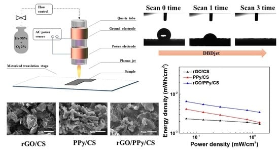
Dielectric Barrier Discharge Plasma Jet (DBDjet) Processed Reduced Graphene Oxide/Polypyrrole/Chitosan Nanocomposite Supercapacitors

 , and
, and
Abstract
:
1. Introduction
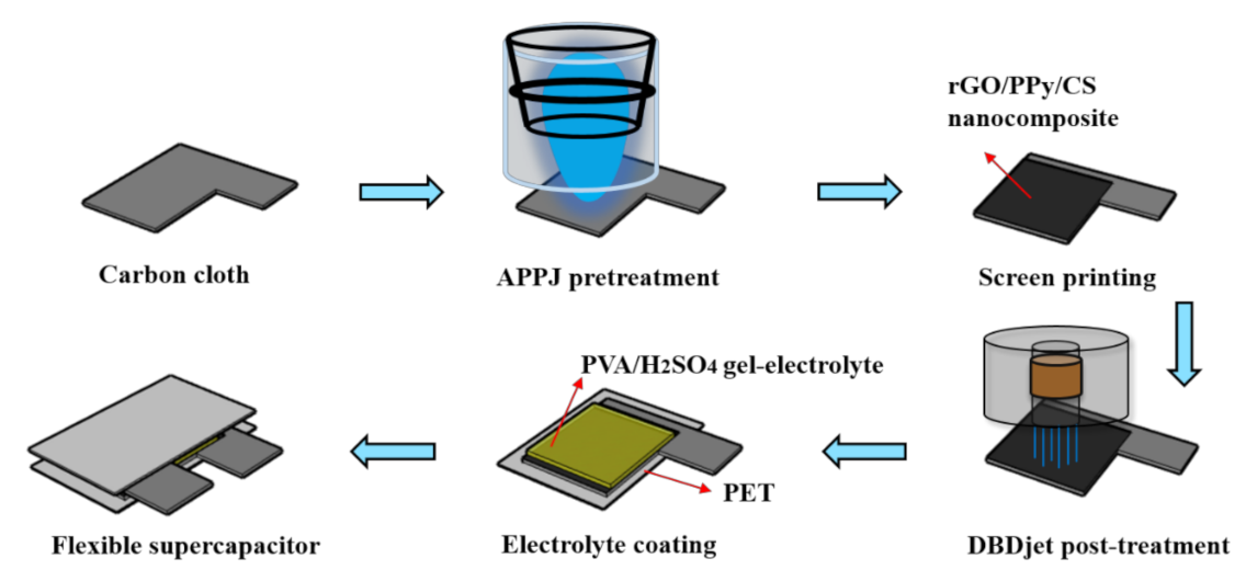
2. Materials and Methods
2.1. Preparation of rGO/PPy/CS, rGO/CS, and PPy/CS Pastes
2.2. Fabrication of rGO/PPy/CS, rGO/CS, and PPy/CS Electrodes
2.3. Preparation of Gel-Electrolyte Solution
2.4. Fabrication of Symmetric Sandwich-Type SCs
2.5. Characterization of rGO/PPy/CS, rGO/CS, and PPy/CS Nanocomposites and SCs
3. Results and Discussion
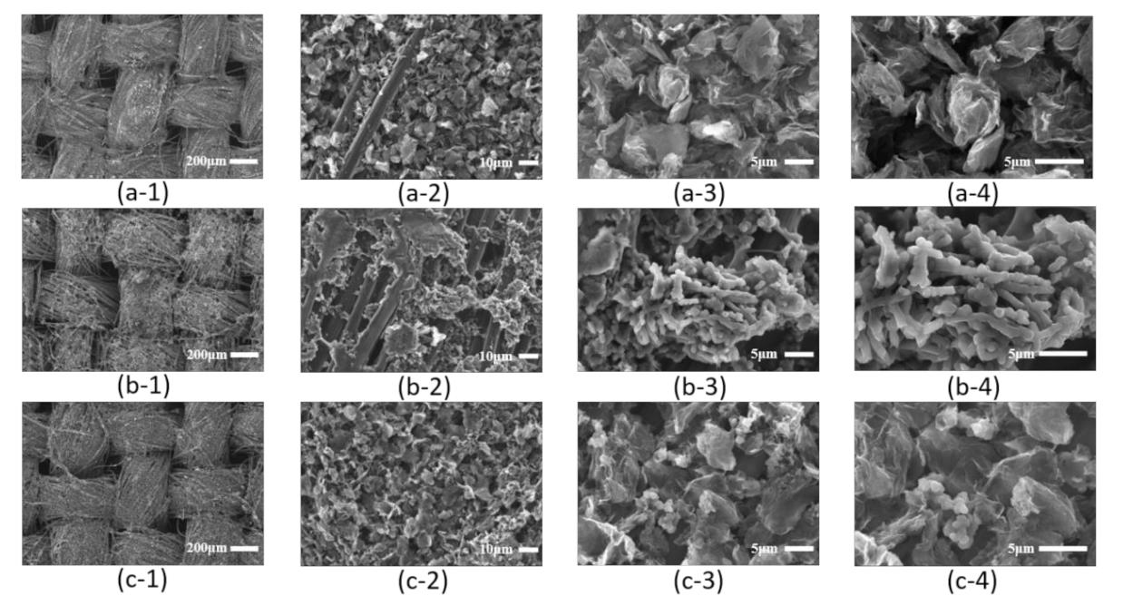
3.1. Surface Morphology of rGO/CS, PPy/CS, and rGO/PPy/CS Electrodes
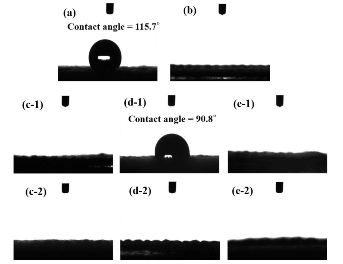
3.2. Hydrophilicity Assessment and XPS Results of rGO/CS, PPy/CS and rGO/PPy/CS Electrodes
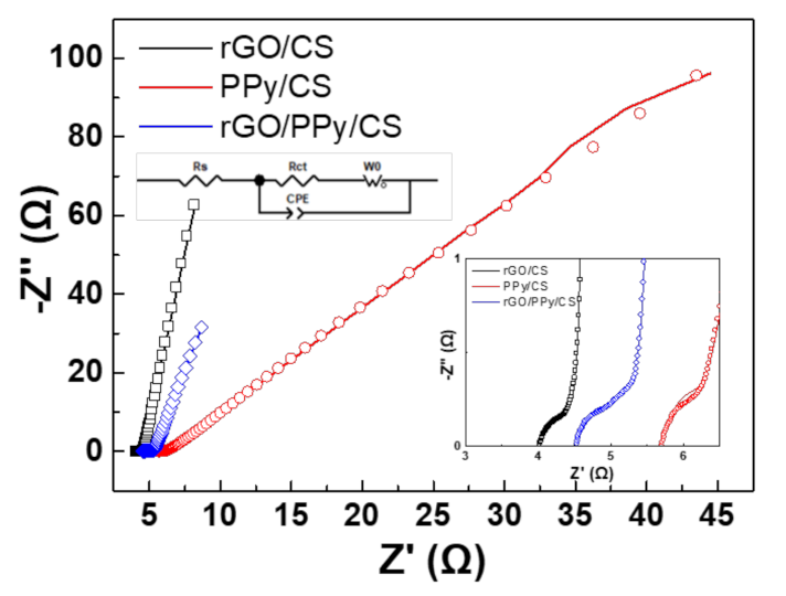
3.3. EIS
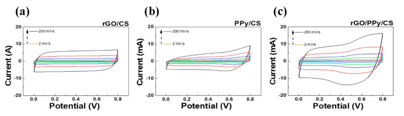
3.4. CV Measurement
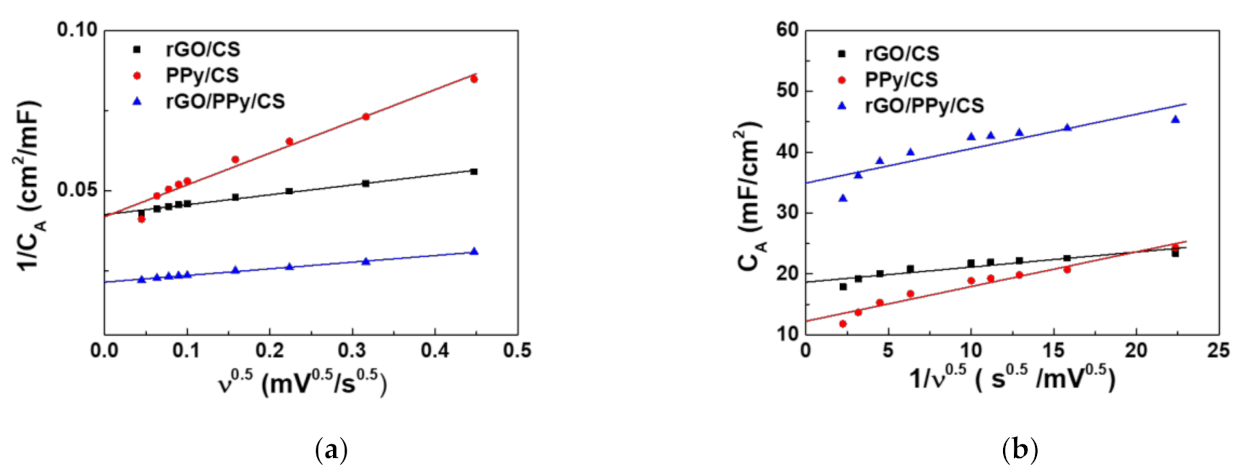
3.5. Trasatti’s Plots
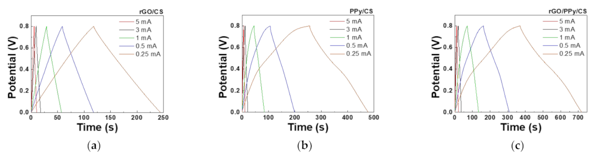
3.6. GCD
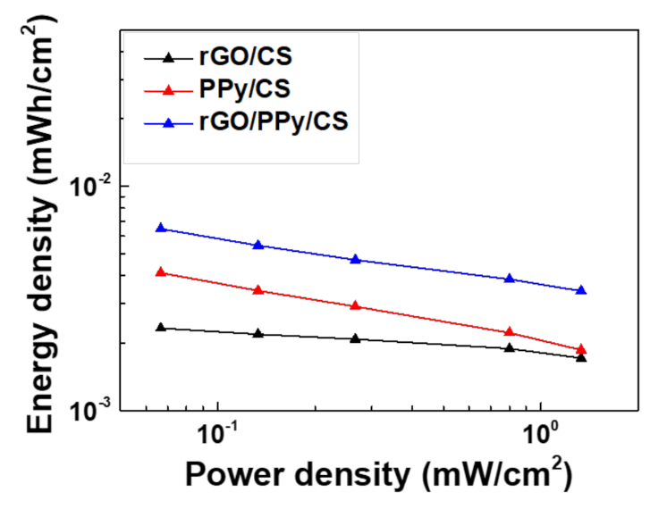
3.7. Ragone Plots
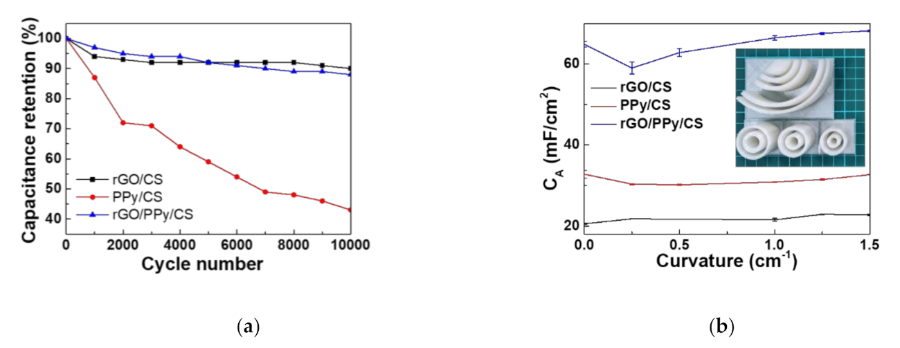
3.8. CV Stability and Bending Tests
4. Conclusions
Supplementary Materials
Author Contributions
Funding
Institutional Review Board Statement
Informed Consent Statement
Data Availability Statement
Acknowledgments
Conflicts of Interest
References
- Tseng, C.-H.; Hsin, J.-C.; Tsai, J.-H.; Chen, J.-Z. Dielectric-barrier-discharge jet treated flexible supercapacitors with carbon cloth current collectors of long-lasting hydrophilicity. J. Electrochem. Soc. 2020, 167, 116511. [Google Scholar] [CrossRef]
- Liu, Y.; Murtaza, I.; Shuja, A.; Meng, H. Interfacial modification for heightening the interaction between PEDOT and substrate towards enhanced flexible solid supercapacitor performance. Chem. Eng. J. 2020, 379, 122326. [Google Scholar] [CrossRef]
- Guan, B.; Li, Y.; Yin, B.; Liu, K.; Wang, D.; Zhang, H.; Cheng, C. Synthesis of hierarchical NiS microflowers for high performance asymmetric supercapacitor. Chem. Eng. J. 2017, 308, 1165–1173. [Google Scholar] [CrossRef]
- Liu, L.; Ye, D.; Yu, Y.; Liu, L.; Wu, Y. Carbon-based flexible micro-supercapacitor fabrication via mask-free ambient micro-plasma-jet etching. Carbon 2017, 111, 121–127. [Google Scholar] [CrossRef]
- Meng, J.; Nie, W.; Zhang, K.; Xu, F.; Ding, X.; Wang, S.; Qiu, Y. Enhancing electrochemical performance of graphene fiber-based supercapacitors by plasma treatment. ACS Appl. Mater. Interfaces 2018, 10, 13652–13659. [Google Scholar] [CrossRef]
- Zhang, X.; Wang, W.; Lu, J.; Hua, L.; Heng, J. Reversible heat of electric double-layer capacitors during galvanostatic charging and discharging cycles. Thermochim. Acta 2016, 636, 1–10. [Google Scholar] [CrossRef]
- Chien, H.-H.; Cheng, Y.-C.; Hao, Y.-C.; Hsu, C.-C.; Cheng, I.-C.; Yu, S.; Chen, J.-Z. Nitrogen DC-pulse atmospheric-pressure-plasma jet (APPJ)-processed reduced graphene oxide (rGO)-carbon black (CB) nanocomposite electrodes for supercapacitor applications. Diam. Relat. Mater. 2018, 88, 23–31. [Google Scholar] [CrossRef]
- Yang, C.-H.; Kuok, F.-H.; Liao, C.-Y.; Wan, T.-H.; Chen, C.-W.; Hsu, C.-C.; Cheng, I.-C.; Chen, J.-Z. Flexible reduced graphene oxide supercapacitor fabricated using a nitrogen dc-pulse atmospheric-pressure plasma jet. Mater. Res. Express 2017, 4, 025504. [Google Scholar] [CrossRef]
- Chen, J.-Z.; Wang, C.; Hsu, C.-C.; Cheng, I.-C. Ultrafast synthesis of carbon-nanotube counter electrodes for dye-sensitized solar cells using an atmospheric-pressure plasma jet. Carbon 2016, 98, 34–40. [Google Scholar] [CrossRef]
- Wang, J.-G.; Yang, Y.; Huang, Z.-H.; Kang, F. Synthesis and electrochemical performance of MnO2/CNTs–embedded carbon nanofibers nanocomposites for supercapacitors. Electrochim. Acta 2012, 75, 213–219. [Google Scholar] [CrossRef]
- Hosseini, M.G.; Shahryari, E. A novel high-performance supercapacitor based on chitosan/graphene oxide-MWCNT/polyaniline. J. Colloid Interface Sci. 2017, 496, 371–381. [Google Scholar] [CrossRef]
- Chien, H.-H.; Liao, C.-Y.; Hao, Y.-C.; Hsu, C.-C.; Cheng, I.-C.; Yu, S.; Chen, J.-Z. Improved performance of polyaniline/reduced-graphene-oxide supercapacitor using atmospheric-pressure-plasma-jet surface treatment of carbon cloth. Electrochim. Acta 2018, 260, 391–399. [Google Scholar] [CrossRef]
- Antolini, E. Graphene as a new carbon support for low-temperature fuel cell catalysts. Appl. Catal. B—Environ. 2012, 123, 52–68. [Google Scholar] [CrossRef]
- Yin, Z.; Zhu, J.; He, Q.; Cao, X.; Tan, C.; Chen, H.; Yan, Q.; Zhang, H. Graphene-based materials for solar cell applications. Adv. Energy Mater. 2014, 4, 1300574. [Google Scholar] [CrossRef]
- Arivu, M.; Masud, J.; Umapathi, S.; Nath, M. Facile synthesis of Ni3B/rGO nanocomposite as an efficient electrocatalyst for the oxygen evolution reaction in alkaline media. Electrochem. Commun. 2018, 86, 121–125. [Google Scholar] [CrossRef]
- Rames, S.; Yadav, H.M.; Lee, Y.J.; Hong, G.W.; Kathalingam, A.; Sivasamy, A.; Kim, H.S.; Kim, H.S.; Kim, J.H. Porous materials of nitrogen doped graphene oxide@SnO2 electrode for capable supercapacitor application. Sci. Rep. 2019, 9. [Google Scholar] [CrossRef]
- Zheng, W.; Li, S.; Yu, X.; Chen, C.; Huang, H.; Huang, Y.; Li, L. Synthesis of hierarchical reduced graphene oxide/SnO2/polypyrrole ternary composites with high electrochemical performance. Mater. Res. Bull. 2016, 80, 303–308. [Google Scholar] [CrossRef]
- Lim, S.P.; Huang, N.M.; Lim, H.N. Solvothermal synthesis of SnO2/graphene nanocomposites for supercapacitor application. Ceram. Int. 2013, 39, 6647–6655. [Google Scholar] [CrossRef]
- Xiang, C.; Li, M.; Zhi, M.; Manivannan, A.; Wu, N. A reduced graphene oxide/Co3O4 composite for supercapacitor electrode. J. Power Sources 2013, 226, 65–70. [Google Scholar] [CrossRef] [Green Version]
- An, H.; Wang, Y.; Wang, X.; Zheng, L.; Wang, X.; Yi, L.; Bai, L.; Zhang, X. Polypyrrole/carbon aerogel composite materials for supercapacitor. J. Power Sources 2010, 195, 6964–6969. [Google Scholar] [CrossRef]
- Ramya, R.; Sivasubramanian, R.; Sangaranarayanan, M. Conducting polymers-based electrochemical supercapacitors—Progress and prospects. Electrochim. Acta 2013, 101, 109–129. [Google Scholar] [CrossRef]
- Snook, G.A.; Kao, P.; Best, A.S. Conducting-polymer-based supercapacitor devices and electrodes. J. Power Sources 2011, 196, 1–12. [Google Scholar] [CrossRef]
- Liu, Y.; Qu, G.; Sun, Q.; Jia, H.; Wang, T.; Zhu, L. Endogenously activated persulfate by non-thermal plasma for Cu(II)-EDTA decomplexation: Synergistic effect and mechanisms. Chem. Eng. J. 2021, 406, 126774. [Google Scholar] [CrossRef]
- Bai, B.C.; Lee, H.-U.; Lee, C.W.; Lee, Y.-S.; Im, J.S. N2 plasma treatment on activated carbon fibers for toxic gas removal: Mechanism study by electrochemical investigation. Chem. Eng. J. 2016, 306, 260–268. [Google Scholar] [CrossRef]
- Zhang, T.; Wu, J.; Chen, J.; Pan, Q.; Wang, X.; Zhong, H.; Tao, R.; Yan, J.; Hu, Y.; Ye, X. Activating Titanium Metal with H2 Plasma for the Hydrogen Evolution Reaction. ACS Appl. Mater. Interfaces 2021, 13, 24682–24691. [Google Scholar] [CrossRef]
- Tao, L.; Duan, X.; Wang, C.; Duan, X.; Wang, S. Plasma-engineered MoS2 thin-film as an efficient electrocatalyst for hydrogen evolution reaction. Chem. Commun. 2015, 51, 7470–7473. [Google Scholar] [CrossRef] [PubMed]
- Abuzairi, T.; Okada, M.; Mochizuki, Y.; Poespawati, N.R.; Purnamaningsih, R.W.; Nagatsu, M. Maskless functionalization of a carbon nanotube dot array biosensor using an ultrafine atmospheric pressure plasma jet. Carbon 2015, 89, 208–216. [Google Scholar] [CrossRef]
- Hsu, C.-T.; Tsai, J.-H.; Huang, T.-M.; Hsin, J.-C.; Chen, J.-Z.; Lee, B.-S.; Yang, T.-C. Atmospheric pressure plasma jet treatment enhances the effect of Alloy Primer on the bond strength between polymethyl methacrylate and stainless steels: Application for retention of magnetic attachment to resin denture base. Colloids Surf. B Biointerfaces 2021, 197, 111440. [Google Scholar] [CrossRef]
- Puač, N.; Gherardi, M.; Shiratani, M. Plasma agriculture: A rapidly emerging field. Plasma Process. Polym. 2018, 15, 1700174. [Google Scholar] [CrossRef]
- Graves, D.B. Low temperature plasma biomedicine: A tutorial review. Phys. Plasmas 2014, 21, 080901. [Google Scholar] [CrossRef] [Green Version]
- Chen, J.-Z.; Hsu, C.-C.; Wang, C.; Liao, W.-Y.; Wu, C.-H.; Wu, T.-J.; Liu, H.-W.; Chang, H.; Lien, S.-T.; Li, H.-C. Rapid atmospheric-pressure-plasma-jet processed porous materials for energy harvesting and storage devices. Coatings 2015, 5, 26–38. [Google Scholar] [CrossRef]
- Gerullis, S.; Kretzschmar, B.S.M.; Pfuch, A.; Beier, O.; Beyer, M.; Grünler, B. Influence of atmospheric pressure plasma jet and diffuse coplanar surface barrier discharge treatments on wood surface properties: A comparative study. Plasma Process. Polym. 2018, 15, 1800058. [Google Scholar] [CrossRef]
- Alotaibi, F.; Tung, T.T.; Nine, M.J.; Kabiri, S.; Moussa, M.; Tran, D.N.; Losic, D. Scanning atmospheric plasma for ultrafast reduction of graphene oxide and fabrication of highly conductive graphene films and patterns. Carbon 2018, 127, 113–121. [Google Scholar] [CrossRef]
- Kuok, F.-H.; Liao, C.-Y.; Wan, T.-H.; Yeh, P.-W.; Cheng, I.-C.; Chen, J.-Z. Atmospheric pressure plasma jet processed reduced graphene oxides for supercapacitor application. J. Alloys Compd. 2017, 692, 558–562. [Google Scholar] [CrossRef]
- Chen, J.-Z.; Liao, W.-Y.; Hsieh, W.-Y.; Hsu, C.-C.; Chen, Y.-S. All-vanadium redox flow batteries with graphite felt electrodes treated by atmospheric pressure plasma jets. J. Power Sources 2015, 274, 894–898. [Google Scholar] [CrossRef]
- Chen, Y.; Zhang, X.; Yu, P.; Ma, Y. Stable dispersions of graphene and highly conducting graphene films: A new approach to creating colloids of graphene monolayers. Chem. Commun. 2009, 4527–4529. [Google Scholar] [CrossRef] [PubMed]
- Xu, J.; Wang, D.; Yuan, Y.; Wei, W.; Duan, L.; Wang, L.; Bao, H.; Xu, W. Polypyrrole/reduced graphene oxide coated fabric electrodes for supercapacitor application. Org. Electron. 2015, 24, 153–159. [Google Scholar] [CrossRef]
- Chang, J.-H.; Lin, M.-F.; Kuo, Y.-L.; Yang, C.-R.; Chen, J.-Z. Flexible rGO-SnO2 supercapacitors converted from pastes containing SnCl2 liquid precursor using atmospheric-pressure plasma jet. Ceram. Int. 2021, 47, 1651–1659. [Google Scholar] [CrossRef]
- Keawploy, N.; Venkatkarthick, R.; Wangyao, P.; Zhang, X.; Liu, R.; Qin, J. Eco-friendly conductive cotton-based textile electrodes using silver-and carbon-coated fabrics for advanced flexible supercapacitors. Energy Fuels 2020, 34, 8977–8986. [Google Scholar] [CrossRef]
- Li, Y.; Zhang, Y.; Zhang, H.; Xing, T.-L.; Chen, G.-Q. A facile approach to prepare a flexible sandwich-structured supercapacitor with rGO-coated cotton fabric as electrodes. RSC Adv. 2019, 9, 4180–4189. [Google Scholar] [CrossRef] [Green Version]
- Dubal, D.P.; Lee, S.H.; Kim, J.G.; Kim, W.B.; Lokhande, C.D. Porous polypyrrole clusters prepared by electropolymerization for a high performance supercapacitor. J. Mater. Chem. 2012, 22, 3044–3052. [Google Scholar] [CrossRef]
- Ardizzone, S.; Fregonara, G.; Trasatti, S. “Inner” and “outer” active surface of RuO2 electrodes. Electrochim. Acta 1990, 35, 263–267. [Google Scholar] [CrossRef]
- Tiwari, P.; Jaiswal, J.; Chandra, R. Hierarchal growth of MoS2@ CNT heterostructure for all solid state symmetric supercapacitor: Insights into the surface science and storage mechanism. Electrochim. Acta 2019, 324, 134767. [Google Scholar] [CrossRef]
- Huang, C.; Zhang, J.; Young, N.P.; Snaith, H.J.; Grant, P.S. Solid-state supercapacitors with rationally designed heterogeneous electrodes fabricated by large area spray processing for wearable energy storage applications. Sci. Rep. 2016, 6, 1–15. [Google Scholar] [CrossRef] [Green Version]
- Shao, J.; Zhou, X.; Liu, Q.; Zou, R.; Li, W.; Yang, J.; Hu, J. Mechanism analysis of the capacitance contributions and ultralong cycling-stability of the isomorphous MnO2@ MnO2 core/shell nanostructures for supercapacitors. J. Mater. Chem. A 2015, 3, 6168–6176. [Google Scholar] [CrossRef]
- Gund, G.S.; Dubal, D.P.; Chodankar, N.R.; Cho, J.Y.; Gomez-Romero, P.; Park, C.; Lokhande, C.D. Low-cost flexible supercapacitors with high-energy density based on nanostructured MnO2 and Fe2O3 thin films directly fabricated onto stainless steel. Sci. Rep. 2015, 5, 1–13. [Google Scholar] [CrossRef] [Green Version]
- Zhang, Y.; Liu, Y.; Bai, Y.; Liu, Y.; Xie, E. Boosting the electrochemical properties of carbon materials as bipolar electrodes by introducing oxygen functional groups. RSC Adv. 2020, 10, 35295–35301. [Google Scholar] [CrossRef]


| RS (Ω) | RCT (Ω) | W0 (Ω) | CPE (µsα/Ω) | |
|---|---|---|---|---|
| rGO/CS | 4.05 | 0.16 | 1.0 | 0.0002 |
| PPy/CS | 5.72 | 0.72 | 704.7 | 0.0015 |
| rGO/PPy/CS | 4.53 | 0.45 | 1.3 | 0.002 |
| Ctotal (mF/cm2) | Cin (mF/cm2) | Cout (mF/cm2) | Capacitive Contribution (EDLC:PC) (%) | |
|---|---|---|---|---|
| rGO/CS | 23.5 | 18.7 | 4.9 | 79.4:20.6 |
| PPy/CS | 23.9 | 12.2 | 11.6 | 51.3:48.7 |
| rGO/PPy/Cs | 46.6 | 34.9 | 11.7 | 75.0:25.0 |
| Areal Capacitance (mF/cm2) | |||||
|---|---|---|---|---|---|
| Discharging Current (mA) | |||||
| 5 | 3 | 1 | 0.5 | 0.25 | |
| rGO/CS | 19.30 | 21.25 | 23.42 | 24.64 | 26.23 |
| PPy/CS | 20.97 | 25.01 | 32.77 | 38.57 | 46.34 |
| rGO/PPy/Cs | 38.44 | 43.32 | 52.91 | 61.33 | 72.79 |
Publisher’s Note: MDPI stays neutral with regard to jurisdictional claims in published maps and institutional affiliations. |
© 2021 by the authors. Licensee MDPI, Basel, Switzerland. This article is an open access article distributed under the terms and conditions of the Creative Commons Attribution (CC BY) license (https://creativecommons.org/licenses/by/4.0/).
Share and Cite
Liu, C.; Hung, C.-W.; Cheng, I.-C.; Hsu, C.-C.; Cheng, I.-C.; Chen, J.-Z. Dielectric Barrier Discharge Plasma Jet (DBDjet) Processed Reduced Graphene Oxide/Polypyrrole/Chitosan Nanocomposite Supercapacitors. Polymers 2021, 13, 3585. https://doi.org/10.3390/polym13203585
Liu C, Hung C-W, Cheng I-C, Hsu C-C, Cheng I-C, Chen J-Z. Dielectric Barrier Discharge Plasma Jet (DBDjet) Processed Reduced Graphene Oxide/Polypyrrole/Chitosan Nanocomposite Supercapacitors. Polymers. 2021; 13(20):3585. https://doi.org/10.3390/polym13203585
Chicago/Turabian StyleLiu, Chen, Cheng-Wei Hung, I-Chung Cheng, Cheng-Che Hsu, I-Chun Cheng, and Jian-Zhang Chen. 2021. "Dielectric Barrier Discharge Plasma Jet (DBDjet) Processed Reduced Graphene Oxide/Polypyrrole/Chitosan Nanocomposite Supercapacitors" Polymers 13, no. 20: 3585. https://doi.org/10.3390/polym13203585