
Material Anisotropy in Additively Manufactured Polymers and Polymer Composites: A Review


Abstract
:1. Introduction
2. Material Anisotropy in Additively Manufactured Polymer Parts
2.1. Mechanical Anisotropy
2.2. Electrical Anisotropy
2.3. Thermal Anisotropy
3. Methods for Mitigating Material Anisotropy
3.1. Polymer and Monomer Alternation
3.2. Adding Fillers
3.3. Altering 3-D Printing Machine Parameters
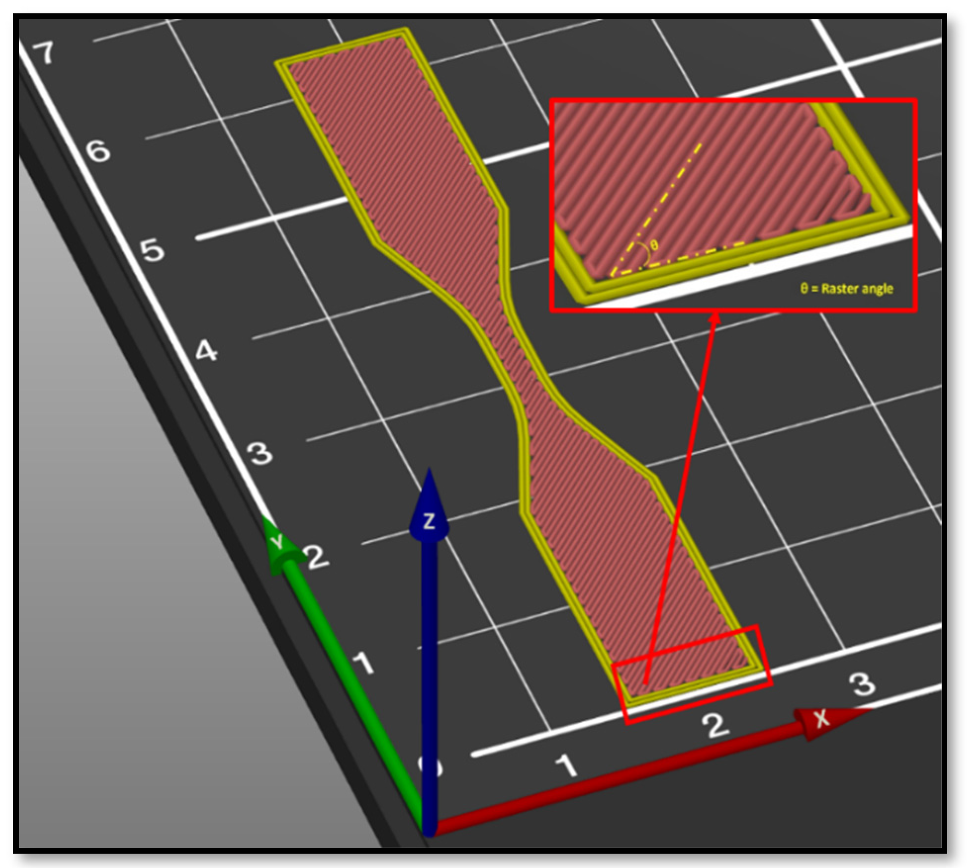
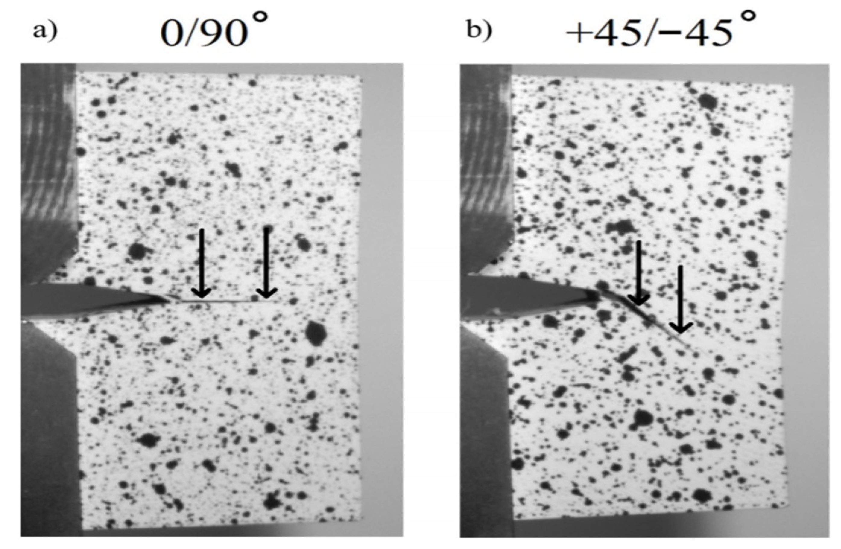
3.3.1. Raster Angle
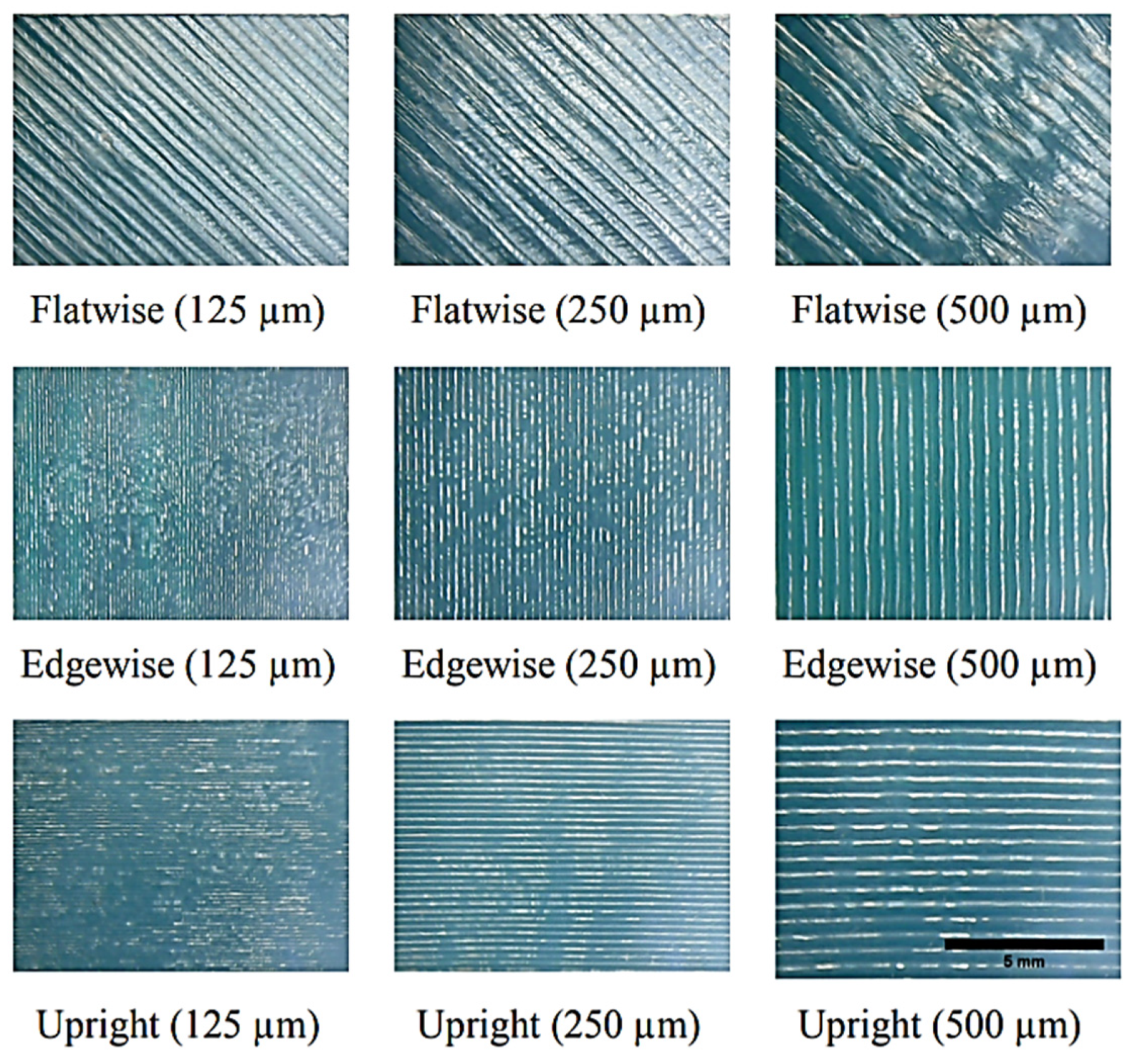
3.3.2. Printing Layer Thickness
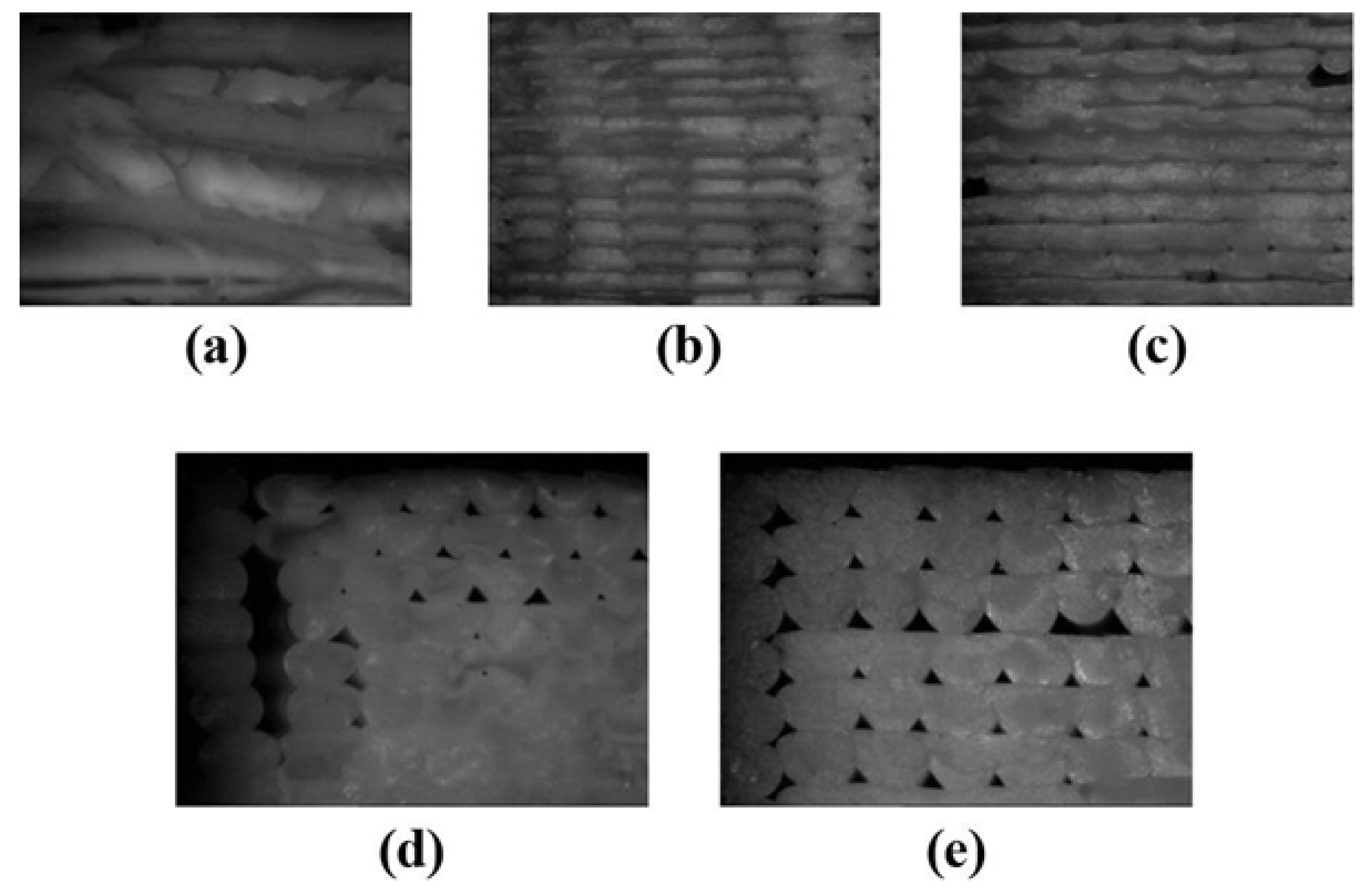
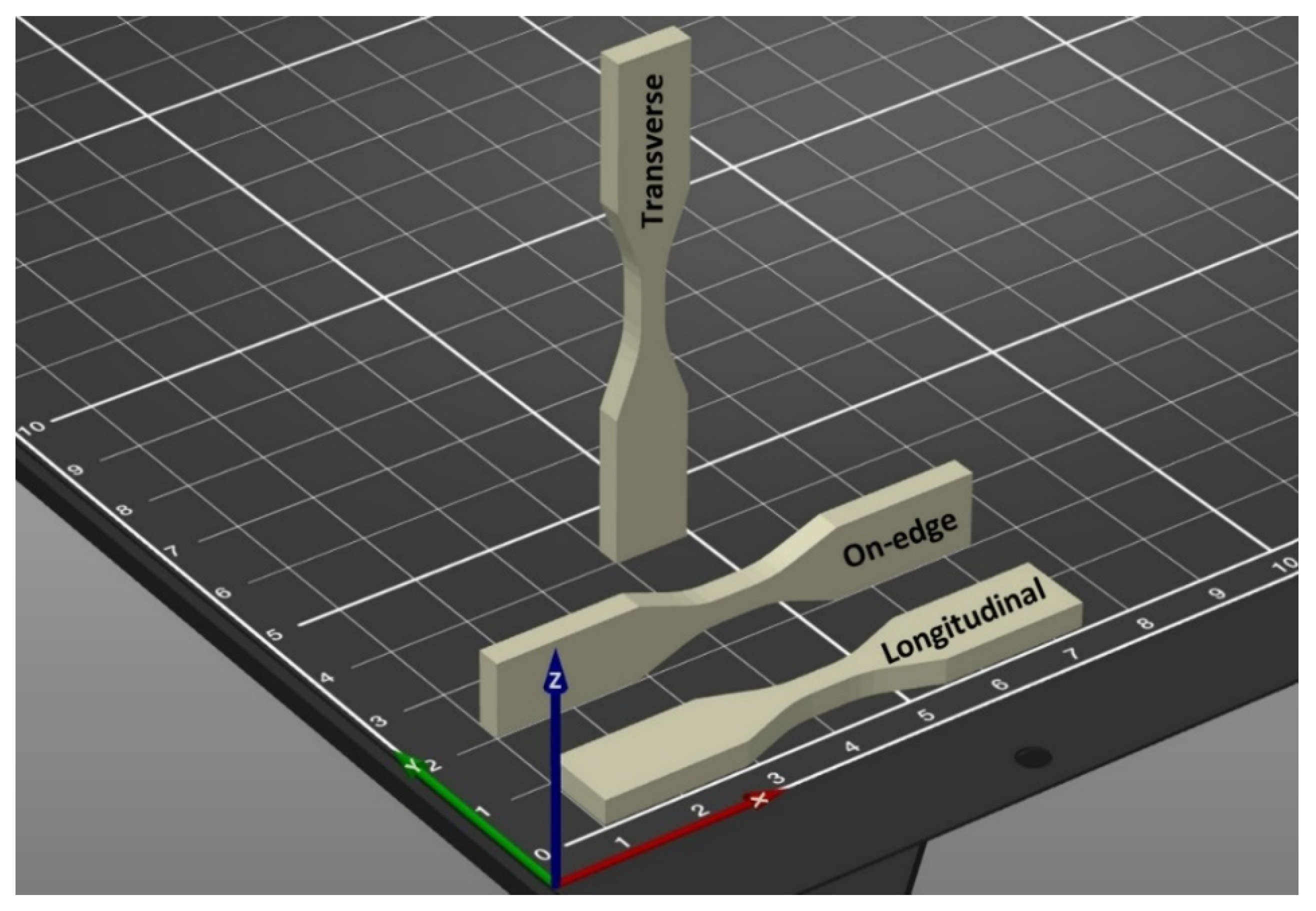
3.3.3. Build Orientation
3.3.4. Feed Rate
3.4. Post-Processing Heat Treatment
Air Gap
3.5. Other Related Factors and Parameters
4. Research Challenges
5. Recommendations on Future Work
6. Concluding Remarks
Author Contributions
Funding
Institutional Review Board Statement
Informed Consent Statement
Data Availability Statement
Acknowledgments
Conflicts of Interest
References
- Ngo, T.D.; Kashani, A.; Imbalzano, G.; Nguyen, K.T.Q.; Hui, D. Additive manufacturing (3D printing): A review of materials, methods, applications and challenges. Compos. Part B Eng. 2018, 143, 172–196. [Google Scholar] [CrossRef]
- Hull, C.W. Apparatus for Production Of Three-Dimensional Objects by Stereolithography. U.S. Patent Application No. 5556590A, 11 September 1996. [Google Scholar]
- Campbell, T.A.; Ivanova, O.S. 3D printing of multifunctional nanocomposites. Nano Today 2013, 8, 119–120. [Google Scholar] [CrossRef]
- De Leon, A.C.; Chen, Q.; Palaganas, N.B.; Palaganas, J.O.; Manapat, J.; Advincula, R.C. High performance polymer nanocomposites for additive manufacturing applications. React. Funct. Polym. 2016, 103, 141–155. [Google Scholar] [CrossRef]
- Feng, X.; Yang, Z.; Rostom, S.S.H.; Dadmun, M.; Xie, Y.; Wang, S. Structural, mechanical, and thermal properties of 3D printed L-CNC/acrylonitrile butadiene styrene nanocomposites. J. Appl. Polym. Sci. 2017, 134. [Google Scholar] [CrossRef]
- Kamrani, A.K.; Nasr, E.A. Rapid Prototyping: Theory and Practice; Springer Science & Business Media: Berlin, Germany, 2006; Volume 6. [Google Scholar]
- Saroia, J.; Wang, Y.; Wei, Q.; Lei, M.; Li, X.; Guo, Y.; Zhang, K. A review on 3D printed matrix polymer composites: Its potential and future challenges. Int. J. Adv. Manuf. Technol. 2020, 106, 1695–1721. [Google Scholar] [CrossRef]
- Kok, Y.; Tan, X.P.; Wang, P.; Nai, M.L.S.; Loh, N.H.; Liu, E.; Tor, S.B. Anisotropy and heterogeneity of microstructure and mechanical properties in metal additive manufacturing: A critical review. Mater. Des. 2018, 139, 565–586. [Google Scholar] [CrossRef]
- Gao, X.; Qi, S.; Kuang, X.; Su, Y.; Li, J.; Wang, D.J.A.M. Fused filament fabrication of polymer materials: A review of interlayer bond. Addit. Manuf. 2020, 37, 101658. [Google Scholar] [CrossRef]
- Goh, G.D.; Yap, Y.L.; Tan, H.K.J.; Sing, S.L.; Goh, G.L.; Yeong, W.Y. Process–structure–properties in polymer additive manufacturing via material extrusion: A review. Crit. Rev. Solid State Mater. Sci. 2020, 45, 113–133. [Google Scholar] [CrossRef]
- Cuan-Urquizo, E.; Barocio, E.; Tejada-Ortigoza, V.; Pipes, R.B.; Rodriguez, C.A.; Roman-Flores, A. Characterization of the mechanical properties of FFF structures and materials: A review on the experimental, computational and theoretical approaches. Materials 2019, 12, 895. [Google Scholar] [CrossRef] [Green Version]
- Baker, A.M.; Mccoy, J.; Majumdar, B.S.; Rumley-Ouellette, B.; Wahry, J.; Marchi, A.N.; Bernardin, J.D.; Spernjak, D. Measurement and modelling of thermal and mechanical anisotropy of parts additively manufactured using fused deposition modelling (FDM). In Proceedings of the 11th International Workshop on Structural Health Monitoring, Stanford, CA, USA, 12–14 September 2017. [Google Scholar]
- Cooke, W.; Anne Tomlinson, R.; Burguete, R.; Johns, D.; Vanard, G. Anisotropy, homogeneity and ageing in an SLS polymer. Rapid Prototyp. J. 2011, 17, 269–279. [Google Scholar] [CrossRef]
- Monzón, M.; Ortega, Z.; Hernández, A.; Paz, R.; Ortega, F. Anisotropy of photopolymer parts made by digital light processing. Materials 2017, 10, 64. [Google Scholar] [CrossRef] [PubMed] [Green Version]
- Kotlinski, J. Mechanical properties of commercial rapid prototyping materials. Rapid Prototyp. J. 2014, 20, 499–510. [Google Scholar] [CrossRef]
- Zohdi, N.; Tareq, S.; Yang, C. Investigation on mechanical anisotropy of high impact polystyrene fabricated via fused deposition modelling. In Proceedings of the International Conference on Mechanical and Manufacturing Engineering Research and Practice, Sydney, Australia, 24–28 November 2019; pp. 24–28. [Google Scholar]
- Dizon, J.R.C.; Espera, A.H.; Chen, Q.; Advincula, R.C. Mechanical characterization of 3D-printed polymers. Addit. Manuf. 2018, 20, 44–67. [Google Scholar] [CrossRef]
- Ajoku, U.; Saleh, N.; Hopkinson, N.; Hague, R.; Erasenthiran, P. Investigating mechanical anisotropy and end-of-vector effect in laser-sintered nylon parts. Proc. Inst. Mech. Eng. Part B J. Eng. Manuf. 2006, 220, 1077–1086. [Google Scholar] [CrossRef] [Green Version]
- Beitz, S.; Uerlich, R.; Bokelmann, T.; Diener, A.; Vietor, T.; Kwade, A. Influence of powder deposition on powder bed and specimen properties. Materials 2019, 12, 297. [Google Scholar] [CrossRef] [PubMed] [Green Version]
- Wörz, A.; Drummer, D. Tribological anisotropy of selective laser sintered PA12 parts. Polym. Test. 2018, 70, 117–126. [Google Scholar] [CrossRef]
- Majewski, C.; Hopkinson, N. Effect of section thickness and build orientation on tensile properties and material characteristics of laser sintered nylon-12 parts. Rapid Prototyp. J. 2011, 17, 176–180. [Google Scholar] [CrossRef]
- Jain, P.K.; Pandey, P.M.; Rao, P.V.M. Experimental investigations for improving part strength in selective laser sintering. Virtual Phys. Prototyp. 2008, 3, 177–188. [Google Scholar] [CrossRef]
- Aznarte, E.; Ayranci, C.; Qureshi, A. Digital light processing (DLP): Anisotropic tensile considerations. In Proceedings of the 28th Annual International Solid Freeform Fabrication Symposium—An Additive Manufacturing Conference, Austin, TX, USA, 7–9 August 2017; pp. 10–203. [Google Scholar]
- Roberson, D.; Shemelya, C.M.; MacDonald, E.; Wicker, R. Expanding the applicability of FDM-type technologies through materials development. Rapid Prototyp. J. 2015, 21, 137–143. [Google Scholar] [CrossRef]
- Türk, D.-A.; Brenni, F.; Zogg, M.; Meboldt, M. Mechanical characterization of 3D printed polymers for fiber reinforced polymers processing. Mater. Des. 2017, 118, 256–265. [Google Scholar] [CrossRef]
- Mohan, N.; Senthil, P.; Vinodh, S.; Jayanth, N. A review on composite materials and process parameters optimisation for the fused deposition modelling process. Virtual Phys. Prototyp. 2017, 12, 47–59. [Google Scholar] [CrossRef]
- Shemelya, C.; de la Rosa, A.; Torrado, A.R.; Yu, K.; Domanowski, J.; Bonacuse, P.J.; Martin, R.E.; Juhasz, M.; Hurwitz, F.; Wicker, R.B.; et al. Anisotropy of thermal conductivity in 3D printed polymer matrix composites for space based cube satellites. Addit. Manuf. 2017, 16, 186–196. [Google Scholar] [CrossRef]
- Gnanasekaran, K.; Heijmans, T.; van Bennekom, S.; Woldhuis, H.; Wijnia, S.; de With, G.; Friedrich, H. 3D printing of CNT- and graphene-based conductive polymer nanocomposites by fused deposition modeling. Appl. Mater. Today 2017, 9, 21–28. [Google Scholar] [CrossRef]
- Prajapati, H.; Ravoori, D.; Woods, R.L.; Jain, A. Measurement of anisotropic thermal conductivity and inter-layer thermal contact resistance in polymer fused deposition modeling (FDM). Addit. Manuf. 2018, 21, 84–90. [Google Scholar] [CrossRef]
- Shih, C.-C.; Burnette, M.; Staack, D.; Wang, J.; Tai, B.L. Effects of cold plasma treatment on interlayer bonding strength in FFF process. Addit. Manuf. 2019, 25, 104–111. [Google Scholar] [CrossRef]
- Rybachuk, M.; Mauger, C.A.; Fiedler, T.; Öchsner, A. Anisotropic mechanical properties of fused deposition modeled parts fabricated by using acrylonitrile butadiene styrene polymer. J. Polym. Eng. 2017, 37, 699–706. [Google Scholar] [CrossRef]
- Lee, J.; Huang, A. Fatigue analysis of FDM materials. Rapid Prototyp. J. 2013, 19, 291–299. [Google Scholar] [CrossRef]
- Wu, W.; Geng, P.; Li, G.; Zhao, D.; Zhang, H.; Zhao, J. Influence of layer thickness and raster angle on the mechanical properties of 3D-printed PEEK and a comparative mechanical study between PEEK and ABS. Materials 2015, 8, 5834–5846. [Google Scholar] [CrossRef] [PubMed]
- Cantrell, J.; Rohde, S.; Damiani, D.; Gurnani, R.; DiSandro, L.; Anton, J.; Young, A.; Jerez, A.; Steinbach, D.; Kroese, C.; et al. Experimental Characterization of the Mechanical Properties of 3D Printed ABS and Polycarbonate Parts; Springer: Cham, Switzerland; pp. 89–105.
- Yang, C.; Tian, X.; Li, D.; Cao, Y.; Zhao, F.; Shi, C. Influence of thermal processing conditions in 3D printing on the crystallinity and mechanical properties of PEEK material. J. Mater. Process. Technol. 2017, 248, 1–7. [Google Scholar] [CrossRef]
- Knoop, F.; Schoeppner, V.; Knoop, F.; Schoeppner, V. Mechanical and thermal properties of FDM parts manufactured with polyamide 12. In Proceedings of the Solid Freeform Fabrication Symposium, Austin, TX, USA, 10–12 August 2015; pp. 935–948. [Google Scholar]
- Ding, Q.; Li, X.; Zhang, D.; Zhao, G.; Sun, Z. Anisotropy of poly(lactic acid)/carbon fiber composites prepared by fused deposition modeling. J. Appl. Polym. Sci. 2020, 137, 48786. [Google Scholar] [CrossRef]
- Zhang, J.; Yang, B.; Fu, F.; You, F.; Dong, X.; Dai, M. Resistivity and its anisotropy characterization of 3D-printed acrylonitrile butadiene styrene copolymer (ABS)/carbon black (CB) composites. Appl. Sci. 2017, 7, 20. [Google Scholar] [CrossRef] [Green Version]
- Partain, S.C. Fused Deposition Modeling with Localized Pre-Deposition Heating Using Forced Air. M.Sc. Thesis, College of Engineering, Montana State University-Bozeman, Bozeman, MT, USA, 2007. [Google Scholar]
- Aliheidari, N.; Christ, J.; Tripuraneni, R.; Nadimpalli, S.; Ameli, A. Interlayer adhesion and fracture resistance of polymers printed through melt extrusion additive manufacturing process. Mater. Des. 2018, 156, 351–361. [Google Scholar] [CrossRef]
- Jayanth, N.; Senthil, P.; Prakash, C. Effect of chemical treatment on tensile strength and surface roughness of 3D-printed ABS using the FDM process. Virtual Phys. Prototyp. 2018, 13, 155–163. [Google Scholar] [CrossRef]
- Percoco, G.; Lavecchia, F.; Galantucci, L.M. Compressive properties of FDM rapid prototypes treated with a low cost chemical finishing. Res. J. Appl. Sci. Eng. Technol. 2012, 4, 3838–3842. [Google Scholar]
- Afrose, M.F.; Masood, S.H.; Iovenitti, P.; Nikzad, M.; Sbarski, I. Effects of part build orientations on fatigue behaviour of FDM-processed PLA material. Prog. Addit. Manuf. 2016, 1, 21–28. [Google Scholar] [CrossRef]
- Chacón, J.M.; Caminero, M.A.; García-Plaza, E.; Núñez, P.J. Additive manufacturing of PLA structures using fused deposition modelling: Effect of process parameters on mechanical properties and their optimal selection. Mater. Des. 2017, 124, 143–157. [Google Scholar] [CrossRef]
- Allum, J.; Moetazedian, A.; Gleadall, A.; Silberschmidt, V.V. Interlayer bonding has bulk-material strength in extrusion additive manufacturing: New understanding of anisotropy. Addit. Manuf. 2020, 34, 101297. [Google Scholar] [CrossRef]
- Sonsalla, T.; Moore, A.L.; Meng, W.J.; Radadia, A.D.; Weiss, L. 3-D printer settings effects on the thermal conductivity of acrylonitrile butadiene styrene (ABS). Polym. Test. 2018, 70, 389–395. [Google Scholar] [CrossRef]
- Rodríguez-Panes, A.; Claver, J.; Camacho, A. The influence of manufacturing parameters on the mechanical behaviour of pla and abs pieces manufactured by fdm: A comparative analysis. Materials 2018, 11, 1333. [Google Scholar] [CrossRef] [PubMed] [Green Version]
- Ziemian, C.; Sharma, M.; Ziemi, S. Anisotropic mechanical properties of ABS parts fabricated by fused deposition modelling. In Mechanical Engineering; InTech: London, UK, 2012. [Google Scholar] [CrossRef] [Green Version]
- Zhang, P.; Liu, J.; To, A.C. Role of anisotropic properties on topology optimization of additive manufactured load bearing structures. Scr. Mater. 2017, 135, 148–152. [Google Scholar] [CrossRef]
- Upadhyay, K.; Dwivedi, R.; Singh, A.K. Determination and comparison of the anisotropic strengths of fused deposition modeling P400 ABS. In Advances in 3D Printing & Additive Manufacturing Technologies; Springer: Berlin, Germany, 2017; pp. 9–28. [Google Scholar]
- Walter, R.; Friedrich, K.; Gurka, M. Characterization of mechanical properties of additively manufactured polymers and composites. In AIP Conference Proceedings; AIP Publishing LLC: Melville, NY, USA, 2018; p. 020033. [Google Scholar]
- Hoff, B.W.; Maestas, S.S.; Hayden, S.C.; Harrigan, D.J.; Grudt, R.O.; Ostraat, M.L.; Horwath, J.C.; Leontsev, S. Dielectric strength heterogeneity associated with printing orientation in additively manufactured polymer materials. Addit. Manuf. 2018, 22, 21–30. [Google Scholar] [CrossRef]
- Hmeidat, N.S.; Pack, R.C.; Talley, S.J.; Moore, R.B.; Compton, B.G. Mechanical anisotropy in polymer composites produced by material extrusion additive manufacturing. Addit. Manuf. 2020, 34, 101385. [Google Scholar] [CrossRef]
- Somireddy, M.; Czekanski, A. Anisotropic material behavior of 3D printed composite structures—Material extrusion additive manufacturing. Mater. Des. 2020, 195, 108953. [Google Scholar] [CrossRef]
- Levenhagen, N.P.; Dadmun, M.D. Interlayer diffusion of surface segregating additives to improve the isotropy of fused deposition modeling products. Polymer 2018, 152, 35–41. [Google Scholar] [CrossRef]
- Torrado, A.R.; Shemelya, C.M.; English, J.D.; Lin, Y.; Wicker, R.B.; Roberson, D.A. Characterizing the effect of additives to ABS on the mechanical property anisotropy of specimens fabricated by material extrusion 3D printing. Addit. Manuf. 2015, 6, 16–29. [Google Scholar] [CrossRef]
- Das, S.C.; Ranganathan, R.; Murugan, N.J.R.P.J. Effect of build orientation on the strength and cost of PolyJet 3D printed parts. Rapid Prototyp. J. 2018. [Google Scholar] [CrossRef]
- Ambrosio, D.; Gabrion, X.; Malécot, P.; Amiot, F.; Thibaud, S. Influence of manufacturing parameters on the mechanical properties of projection stereolithography–manufactured specimens. Int. J. Adv. Manuf. Technol. 2020, 106, 265–277. [Google Scholar] [CrossRef] [Green Version]
- Chen, Q.; Mangadlao, J.D.; Wallat, J.; de Leon, A.; Pokorski, J.K.; Advincula, R.C. 3D printing biocompatible polyurethane/poly(lactic acid)/graphene oxide nanocomposites: Anisotropic properties. ACS Appl. Mater. Interfaces 2017, 9, 4015–4023. [Google Scholar] [CrossRef]
- Torrado, A.R.; Roberson, D.A. Failure analysis and anisotropy evaluation of 3D-printed tensile test specimens of different geometries and print raster patterns. J. Fail. Anal. Prev. 2016, 16, 154–164. [Google Scholar] [CrossRef]
- Guessasma, S.; Belhabib, S.; Nouri, H.; Ben Hassana, O. Anisotropic damage inferred to 3D printed polymers using fused deposition modelling and subject to severe compression. Eur. Polym. J. 2016, 85, 324–340. [Google Scholar] [CrossRef]
- Balderrama-Armendariz, C.O.; MacDonald, E.; Espalin, D.; Cortes-Saenz, D.; Wicker, R.; Maldonado-Macias, A. Torsion analysis of the anisotropic behavior of FDM technology. Int. J. Adv. Manuf. Technol. 2018, 96, 307–317. [Google Scholar] [CrossRef]
- Odell, D.; Wright, P.K.; Montero, M.; Roundy, S.; Ahn, S.H. Anisotropic material properties of fused deposition modeling ABS. Rapid Prototyp. J. 2002, 8, 248–257. [Google Scholar] [CrossRef] [Green Version]
- Thomas, J.P.; Rodríguez, J.F.; Renaud, J.E. Mechanical behavior of acrylonitrile butadiene styrene (ABS) fused deposition materials. Experimental investigation. Rapid Prototyp. J. 2001, 7, 148–158. [Google Scholar] [CrossRef]
- Ning, F.; Cong, W.; Hu, Y.; Wang, H. Additive manufacturing of carbon fiber-reinforced plastic composites using fused deposition modeling: Effects of process parameters on tensile properties. J. Compos. Mater. 2016, 51, 451–462. [Google Scholar] [CrossRef]
- Guessasma, S.; Belhabib, S.; Nouri, H. Significance of pore percolation to drive anisotropic effects of 3D printed polymers revealed with X-ray μ-tomography and finite element computation. Polymer 2015, 81, 29–36. [Google Scholar] [CrossRef]
- Torrado Perez, A.R.; Roberson, D.A.; Wicker, R.B. Fracture surface analysis of 3D-printed tensile specimens of novel ABS-based materials. J. Fail. Anal. Prev. 2014, 14, 343–353. [Google Scholar] [CrossRef]
- Prasong, W.; Ishigami, A.; Thumsorn, S.; Kurose, T.; Ito, H. Improvement of interlayer adhesion and heat resistance of biodegradable ternary blend composite 3D Printing. Polymers 2021, 13, 740. [Google Scholar] [CrossRef]
- Christ, J.F.; Aliheidari, N.; Ameli, A.; Pötschke, P. 3D printed highly elastic strain sensors of multiwalled carbon nanotube/thermoplastic polyurethane nanocomposites. Mater. Des. 2017, 131, 394–401. [Google Scholar] [CrossRef]
- Hohimer, C.J.; Petrossian, G.; Ameli, A.; Mo, C.; Pötschke, P. 3D printed conductive thermoplastic polyurethane/carbon nanotube composites for capacitive and piezoresistive sensing in soft pneumatic actuators. Addit. Manuf. 2020, 34, 101281. [Google Scholar] [CrossRef]
- Thaler, D.; Aliheidari, N.; Ameli, A. Mechanical, electrical, and piezoresistivity behaviors of additively manufactured acrylonitrile butadiene styrene/carbon nanotube nanocomposites. Smart Mater. Struct. 2019, 28, 084004. [Google Scholar] [CrossRef]
- Huber, D.L. Controlling anisotropy in stereolithographically printed polymers. J. Mater. Sci. 2019, 54, 2763–2765. [Google Scholar] [CrossRef] [Green Version]
- Gundrati, N.B.; Chakraborty, P.; Zhou, C.; Chung, D.D.L. First observation of the effect of the layer printing sequence on the molecular structure of three-dimensionally printed polymer, as shown by in-plane capacitance measurement. Compos. Part B Eng. 2018, 140, 78–82. [Google Scholar] [CrossRef]
- Spoerk, M.; Savandaiah, C.; Arbeiter, F.; Traxler, G.; Cardon, L.; Holzer, C.; Sapkota, J. Anisotropic properties of oriented short carbon fibre filled polypropylene parts fabricated by extrusion-based additive manufacturing. Compos. Part A Appl. Sci. Manuf. 2018, 113, 95–104. [Google Scholar] [CrossRef]
- Elkholy, A.; Rouby, M.; Kempers, R. Characterization of the anisotropic thermal conductivity of additively manufactured components by fused filament fabrication. Prog. Addit. Manuf. 2019, 4, 497–515. [Google Scholar] [CrossRef]
- Levenhagen, N.P.; Dadmun, M.D. Bimodal molecular weight samples improve the isotropy of 3D printed polymeric samples. Polymer 2017, 122, 232–241. [Google Scholar] [CrossRef]
- Shaffer, S.; Yang, K.; Vargas, J.; Di Prima, M.A.; Voit, W. On reducing anisotropy in 3D printed polymers via ionizing radiation. Polymer 2014, 55, 5969–5979. [Google Scholar] [CrossRef]
- Hwang, S.; Reyes, E.I.; Moon, K.-S.; Rumpf, R.C.; Kim, N.S. Thermo-mechanical characterization of metal/polymer composite filaments and printing parameter study for fused deposition modeling in the 3D printing process. J. Electron. Mater. 2015, 44, 771–777. [Google Scholar] [CrossRef]
- Meng, S.; He, H.; Jia, Y.; Yu, P.; Huang, B.; Chen, J. Effect of nanoparticles on the mechanical properties of acrylonitrile–butadiene–styrene specimens fabricated by fused deposition modeling. J. Appl. Polym. Sci. 2017, 134. [Google Scholar] [CrossRef]
- Goh, G.D.; Yap, Y.L.; Agarwala, S.; Yeong, W.Y. Recent progress in additive manufacturing of fiber reinforced polymer composite. Adv. Mater. Technol. 2019, 4, 1800271. [Google Scholar] [CrossRef] [Green Version]
- Jia, Y.; He, H.; Geng, Y.; Huang, B.; Peng, X. High through-plane thermal conductivity of polymer based product with vertical alignment of graphite flakes achieved via 3D printing. Compos. Sci. Technol. 2017, 145, 55–61. [Google Scholar] [CrossRef]
- Gebisa, A.W.; Lemu, H.G. Investigating effects of fused-deposition modeling (FDM) processing parameters on flexural properties of ULTEM 9085 using designed experiment. Materials 2018, 11, 500. [Google Scholar] [CrossRef] [Green Version]
- Rahman, K.M.; Letcher, T.; Reese, R. Mechanical Properties of Additively Manufactured PEEK Components Using Fused Filament Fabrication; American Society of Mechanical Engineers: New York, NY, USA, 2015. [Google Scholar] [CrossRef]
- Letcher, T.; Waytashek, M. Material property testing of 3D-printed specimen in PLA on an entry-level 3D printer. In ASME 2014 International Mechanical Engineering Congress and Exposition; American Society of Mechanical Engineers: New York, NY, USA, 2014; p. V02AT02A014. [Google Scholar]
- McLouth, T.D.; Severino, J.V.; Adams, P.M.; Patel, D.N.; Zaldivar, R.J. The impact of print orientation and raster pattern on fracture toughness in additively manufactured ABS. Addit. Manuf. 2017, 18, 103–109. [Google Scholar] [CrossRef]
- Rankouhi, B.; Javadpour, S.; Delfanian, F.; Letcher, T. Failure analysis and mechanical characterization of 3D printed ABS with respect to layer thickness and orientation. J. Fail. Anal. Prev. 2016, 16, 467–481. [Google Scholar] [CrossRef]
- Carneiro, O.S.; Silva, A.F.; Gomes, R. Fused deposition modeling with polypropylene. Mater. Des. 2015, 83, 768–776. [Google Scholar] [CrossRef]
- Kovan, V.; Altan, G.; Topal, E.S. Effect of layer thickness and print orientation on strength of 3D printed and adhesively bonded single lap joints. J. Mech. Sci. Technol. 2017, 31, 2197–2201. [Google Scholar] [CrossRef]
- Sood, A.K.; Ohdar, R.K.; Mahapatra, S.S. Parametric appraisal of mechanical property of fused deposition modelling processed parts. Mater. Des. 2010, 31, 287–295. [Google Scholar] [CrossRef]
- Torres, J.; Cotelo, J.; Karl, J.; Gordon, A.P. Mechanical property optimization of FDM PLA in shear with multiple objectives. JOM 2015, 67, 1183–1193. [Google Scholar] [CrossRef]
- Lee, B.H.; Abdullah, J.; Khan, Z.A. Optimization of rapid prototyping parameters for production of flexible ABS object. J. Mater. Process. Technol. 2005, 169, 54–61. [Google Scholar] [CrossRef]
- Rajpurohit, S.R.; Dave, H.K. Effect of process parameters on tensile strength of FDM printed PLA part. Rapid Prototyp. J. 2018, 24, 1317–1324. [Google Scholar] [CrossRef]
- Stansbury, J.W.; Idacavage, M.J. 3D printing with polymers: Challenges among expanding options and opportunities. Dent. Mater. 2016, 32, 54–64. [Google Scholar] [CrossRef] [PubMed]
- Mohamed, O.A.; Masood, S.H.; Bhowmik, J.L. Optimization of fused deposition modeling process parameters: A review of current research and future prospects. Adv. Manuf. 2015, 3, 42–53. [Google Scholar] [CrossRef]
- Christiyan, K.G.J.; Chandrasekhar, U.; Venkateswarlu, K. A study on the influence of process parameters on the mechanical properties of 3D printed ABS composite. IOP Conf. Ser. Mater. Sci. Eng. 2016, 114, 012109. [Google Scholar] [CrossRef]
- Costa, S.F.; Duarte, F.M.; Covas, J.A. Estimation of filament temperature and adhesion development in fused deposition techniques. J. Mater. Process. Technol. 2017, 245, 167–179. [Google Scholar] [CrossRef]
- Wang, J.; Xie, H.; Weng, Z.; Senthil, T.; Wu, L. A novel approach to improve mechanical properties of parts fabricated by fused deposition modeling. Mater. Des. 2016, 105, 152–159. [Google Scholar] [CrossRef]
- Sathish Kumar, K.; Soundararajan, R.; Shanthosh, G.; Saravanakumar, P.; Ratteesh, M. Augmenting effect of infill density and annealing on mechanical properties of PETG and CFPETG composites fabricated by FDM. Mater. Today Proc. 2021, 45, 2186–2191. [Google Scholar] [CrossRef]
- Kantaros, A.; Karalekas, D. Fiber Bragg grating based investigation of residual strains in ABS parts fabricated by fused deposition modeling process. Mater. Des. 2013, 50, 44–50. [Google Scholar] [CrossRef]
- Ravi, A.K.; Deshpande, A.; Hsu, K.H. An in-process laser localized pre-deposition heating approach to inter-layer bond strengthening in extrusion based polymer additive manufacturing. J. Manuf. Process. 2016, 24, 179–185. [Google Scholar] [CrossRef]
- Kishore, V.; Ajinjeru, C.; Nycz, A.; Post, B.; Lindahl, J.; Kunc, V.; Duty, C. Infrared preheating to improve interlayer strength of big area additive manufacturing (BAAM) components. Addit. Manuf. 2017, 14, 7–12. [Google Scholar] [CrossRef]
- Striemann, P.; Hülsbusch, D.; Niedermeier, M.; Walther, F. Optimization and quality evaluation of the interlayer bonding performance of additively manufactured polymer structures. Polymers 2020, 12, 1166. [Google Scholar] [CrossRef]
- Domingo-Espin, M.; Borros, S.; Agullo, N.; Garcia-Granada, A.-A.; Reyes, G. Influence of building parameters on the dynamic mechanical properties of polycarbonate fused deposition modeling parts. 3D Print. Addit. Manuf. 2014, 1, 70–77. [Google Scholar] [CrossRef]
- Croccolo, D.; De Agostinis, M.; Olmi, G. Experimental characterization and analytical modelling of the mechanical behaviour of fused deposition processed parts made of ABS-M30. Comput. Mater. Sci. 2013, 79, 506–518. [Google Scholar] [CrossRef]
- Coogan, T.J.; Kazmer, D.O. Bond and part strength in fused deposition modeling. Rapid Prototyp. J. 2017, 23, 414–422. [Google Scholar] [CrossRef]
- Singh, R.; Sandhu, G.S.; Penna, R.; Farina, I. Investigations for thermal and electrical conductivity of ABS-graphene blended prototypes. Materials 2017, 10, 881. [Google Scholar] [CrossRef] [PubMed] [Green Version]
- Aw, Y.; Yeoh, C.; Idris, M.; Teh, P.; Hamzah, K.; Sazali, S. Effect of printing parameters on tensile, dynamic mechanical, and thermoelectric properties of FDM 3D printed CABS/ZnO composites. Materials 2018, 11, 466. [Google Scholar] [CrossRef] [PubMed] [Green Version]


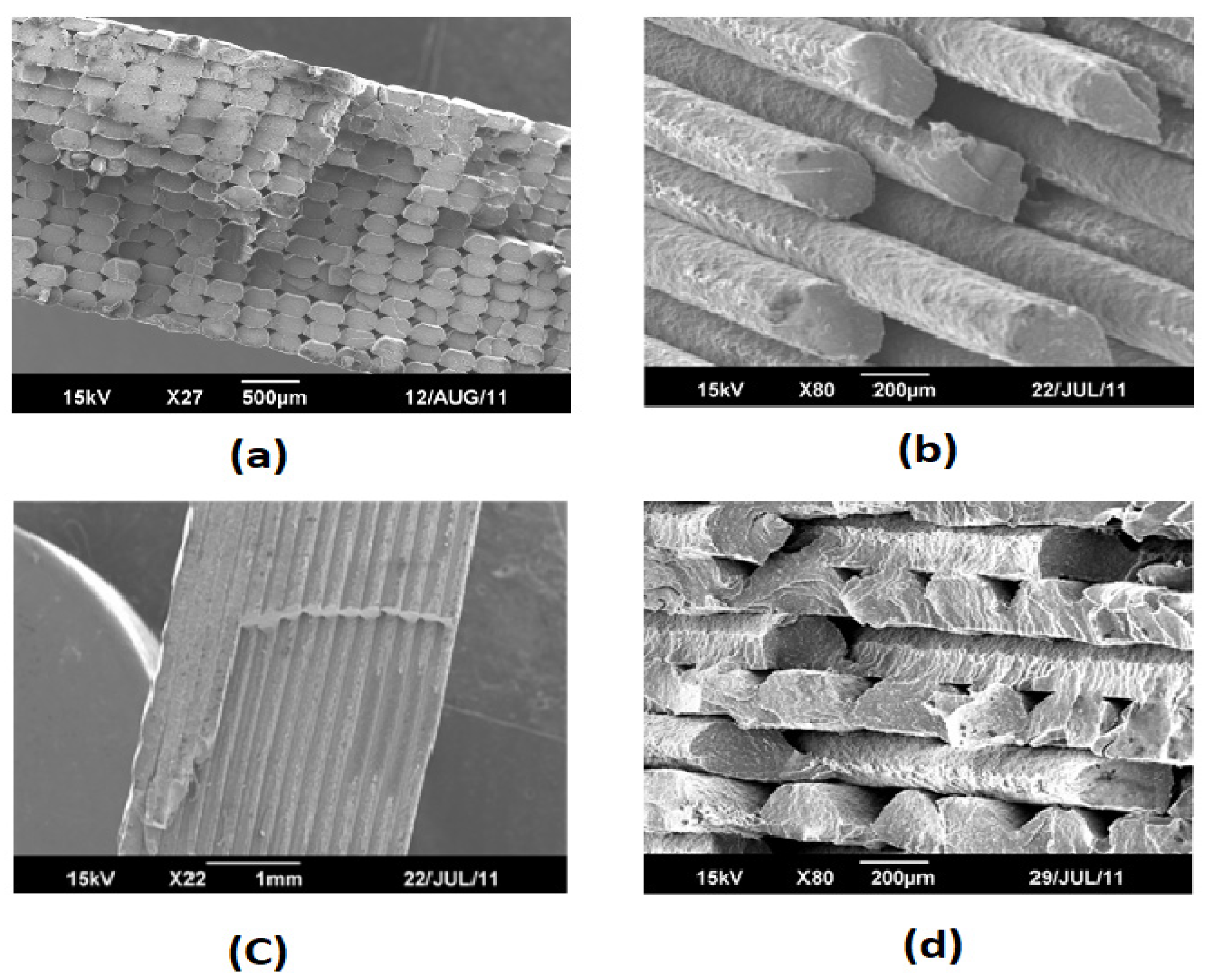
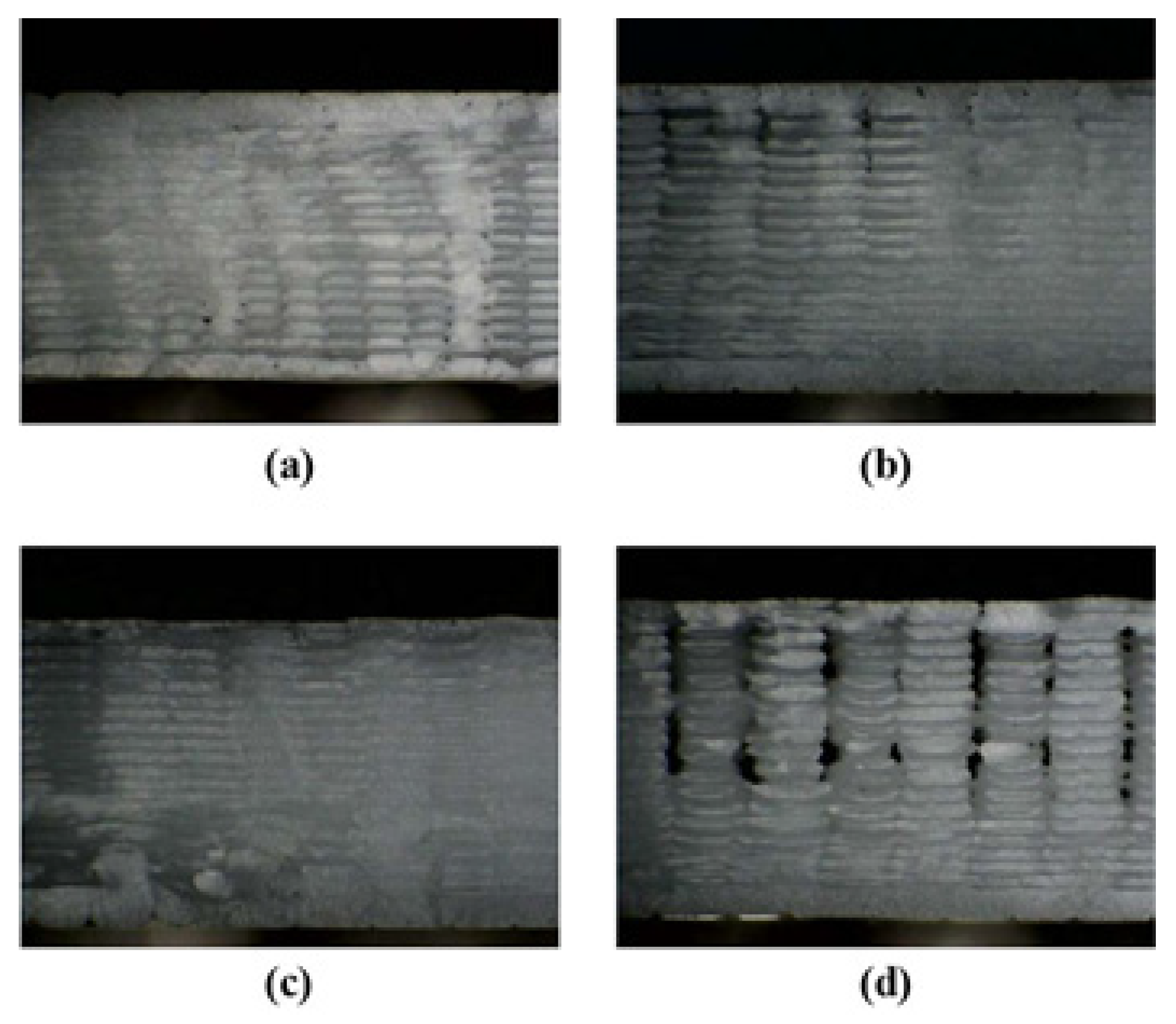
 ) Reprinted with permission from Ref. [88]. 2017, Springer Nature.
) Reprinted with permission from Ref. [88]. 2017, Springer Nature.
) Reprinted with permission from Ref. [88]. 2017, Springer Nature.


| Material Factors | 3D Printing Process Control Parameters | Process Factors of 3D Printing or Additive Manufacturing |
|---|---|---|
| Polymer and monomer alternation [31,32] * | Raster angle [33,34] * | Heat treatment [35,36] ** |
| Adding additives [27,37,38] *** | Layer Thickness [33] ** | Using heat gun, light, and laser [30,39] * |
| Chemical treatment [40,41,42] | Build orientation [14,43] *** | |
| Feed rate [44] * | ||
| Raster width [38,45] | ||
| Bed and nozzle temperatures [35,45] *** | ||
| Infill density [46,47] *** | ||
| Air gap [38] * |
| Material | Printing Method | Anisotropy Type | Anisotropy before Modification | Anisotropy after Modification | Proposed Mitigation Method | References |
|---|---|---|---|---|---|---|
| Acrylonitrile butadiene styrene (ABS) | FDM | Mechanical | 26% | - | - | [50] |
| Nylon | LS | Mechanical | 16% | - | - | [18] |
| ABS | FDM | Mechanical | 25% | - | - | [51] |
| Polyaniline (PA12) | SLS | Mechanical | 3% | - | - | [51] |
| ABS M30 ABS M30i | FDM | Electrical | 75% 26% | - | - | [52] |
| DuraForm-HST Nylon EX | SLS | Electrical | 29% 17.5% | - | - | [52] |
| VeroBlue VeroAmber | Polyjet | Electrical | 53% 71% | - | - | [52] |
| Epoxy/Fumed silica (FS) Epoxy/Nanoclay (NC) Epoxy/Silicon carbide (SiC)+FS Epoxy/SiC+NC | DIW | Mechanical | 1.2% 31.6% 39.6 48.1 | - | - | [53] |
| ABS ABS+ short carbon fibres (SCF) | FFF | Mechanical | 37.7% 82.3% | - | - | [54] |
| Polylactic acid (PLA) | FDM | Mechanical | 77% | 35.7% | Selecting on edge or flat build orientation, changing feed rate and layer thickness | [44] |
| ABS PLA | FDM | Mechanical | 88% 28% | - | Careful selection of build orientation to load direction | [47] |
| PLA | FDM | Mechanical | 166% | 33% | Addition of low molecular weight polymer to high molecular weight polymer | [55] |
| ABS | FDM | Mechanical | 47.7% | 21.97% at 75:25:10 ratio of ABS:UHMWPE:SEBS | Addition of a variety of additives such as Titanium dioxide, Zinc oxide, Strontium titanate, Aluminium oxide, Styrene-Ethylene-Butadiene-Styrene and Ultra-high-molecular-weight polyethylene to decrease anisotropy | [56] |
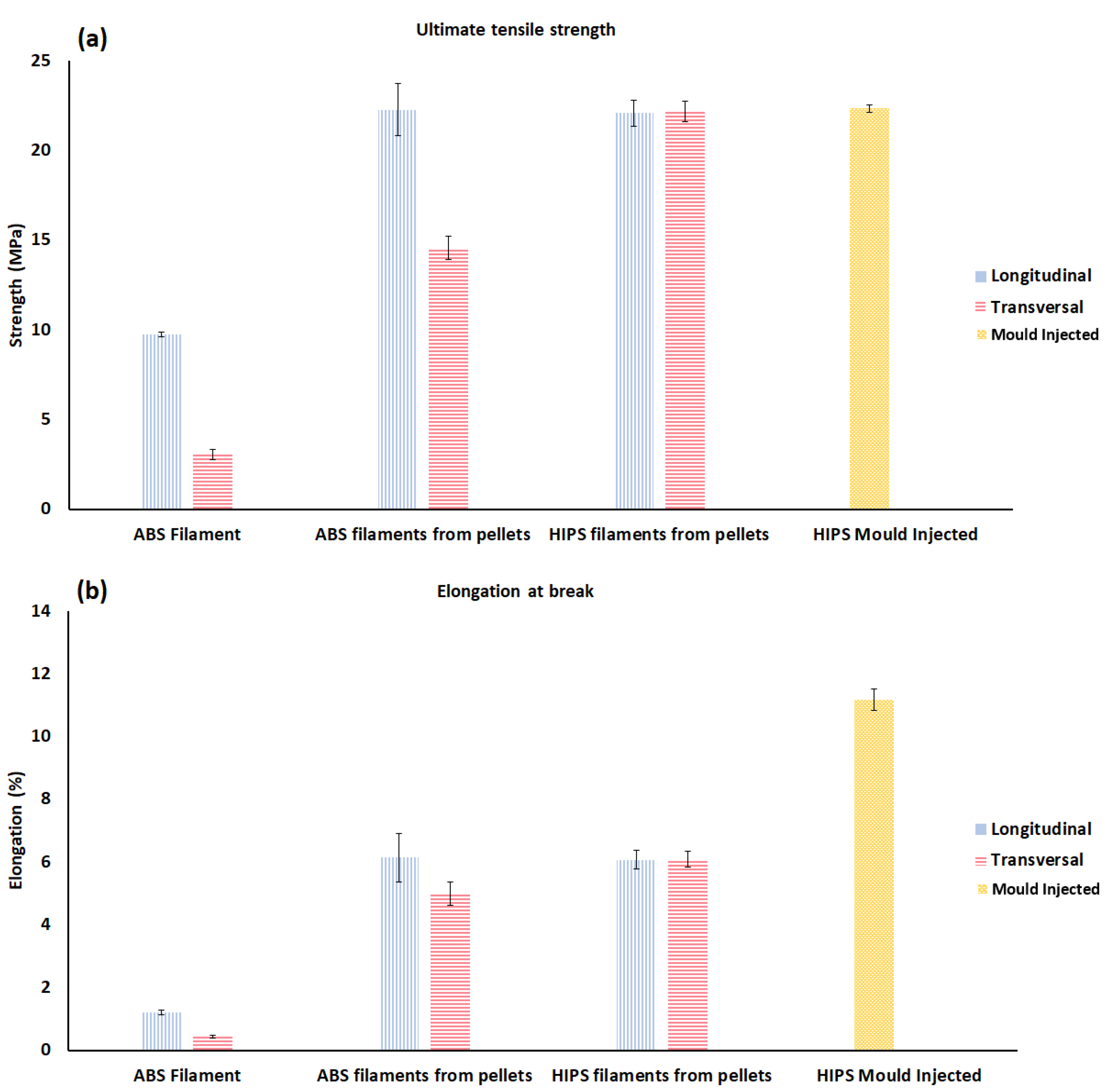
| ABS High impact polystyrene (HIPS) | FDM | Mechanical | 34.63% | 0.5% | Changing the type of polymer from ABS to HIPS | [16] |
| VeroWhitePlus RGD 835 | PolyJet | Mechanical | 7.2% at Flat X and Vertical X | - | - | [57] |
| S-PRO X-GREEN ABS | SLA | Mechanical | 17.8% 56.7% −3.1% | - | - | [58] |
| Poly (butylene terephthalate) (PBT)/Carbon nanotube (CNT) | FDM | Electrical | 32% | - | - | [28] |
| ABS/Graphite ABS/Carbon fibre (CF) | FDM | Thermal | 32% 9% | - | - | [27] |
| Conductive PLA Conductive ABS Conductive PU | FDM | Thermal | 65% 40% 0% | - | Proper selection of polymer can influence thermal conductivity | [12] |
Publisher’s Note: MDPI stays neutral with regard to jurisdictional claims in published maps and institutional affiliations. |
© 2021 by the authors. Licensee MDPI, Basel, Switzerland. This article is an open access article distributed under the terms and conditions of the Creative Commons Attribution (CC BY) license (https://creativecommons.org/licenses/by/4.0/).
Share and Cite
Zohdi, N.; Yang, R. Material Anisotropy in Additively Manufactured Polymers and Polymer Composites: A Review. Polymers 2021, 13, 3368. https://doi.org/10.3390/polym13193368
Zohdi N, Yang R. Material Anisotropy in Additively Manufactured Polymers and Polymer Composites: A Review. Polymers. 2021; 13(19):3368. https://doi.org/10.3390/polym13193368
Chicago/Turabian StyleZohdi, Nima, and Richard (Chunhui) Yang. 2021. "Material Anisotropy in Additively Manufactured Polymers and Polymer Composites: A Review" Polymers 13, no. 19: 3368. https://doi.org/10.3390/polym13193368