
Influence of Manufacturing Process in Structural Health Monitoring and Mechanical Behaviour of CNT Reinforced CFRP and Ti6Al4V Multi-Material Joints


Abstract
:1. Introduction
2. Materials and Methods
2.1. Materials
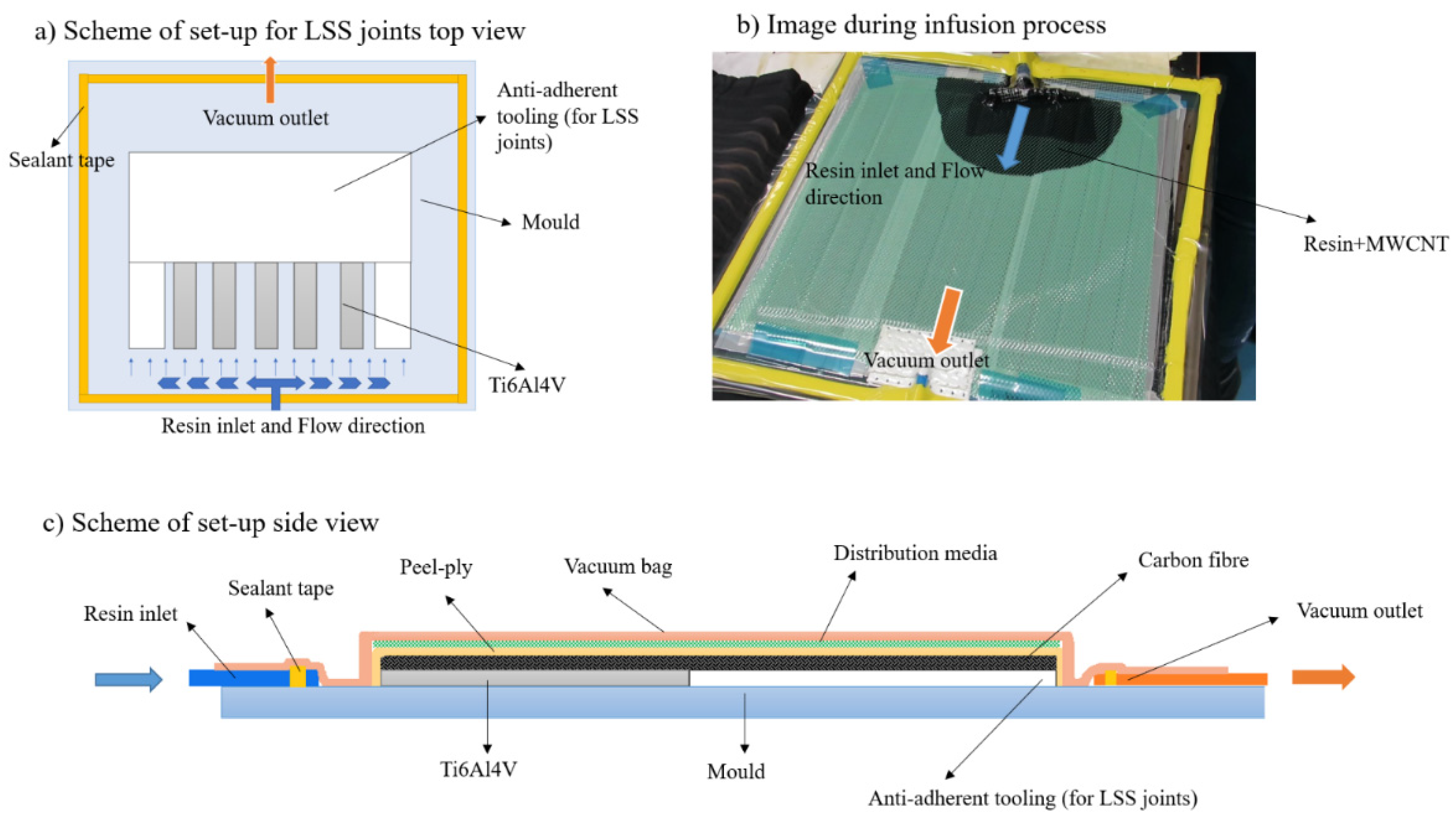
2.2. Manufacturing
2.3. Characterisation
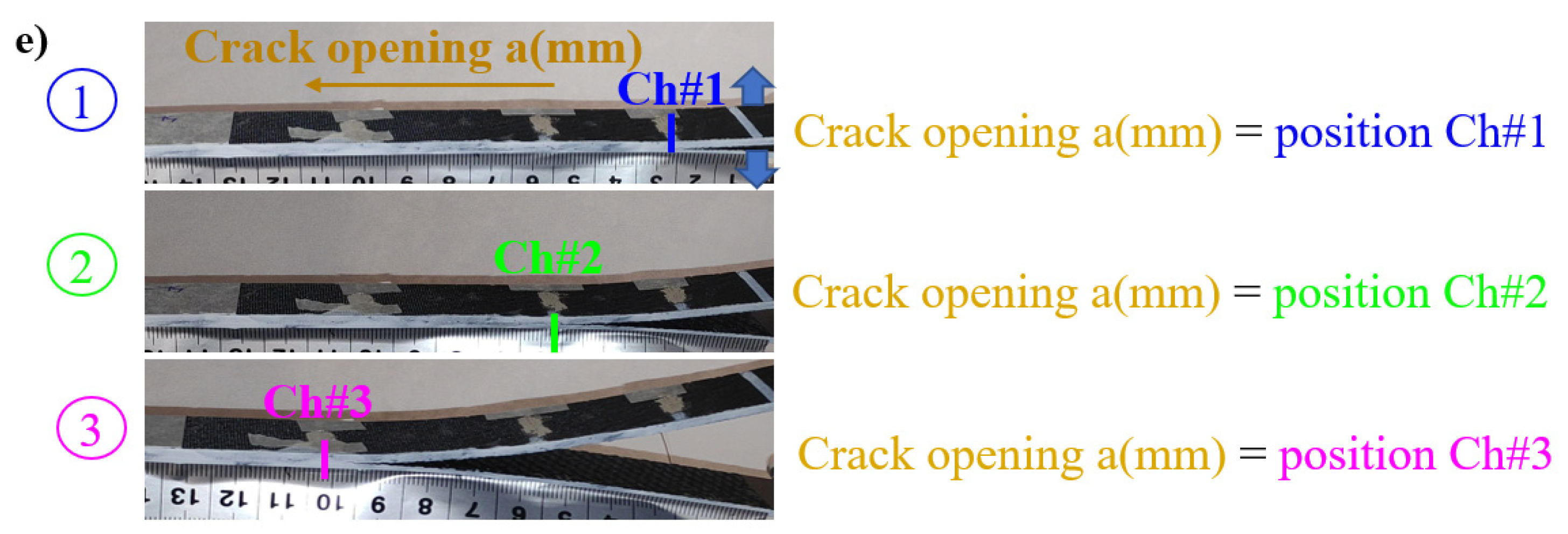
2.3.1. Optical Microscopy and Image Analysis
2.3.2. Lap Shear Test
2.3.3. Mode I Adhesive Fracture Energy (GIC) Test
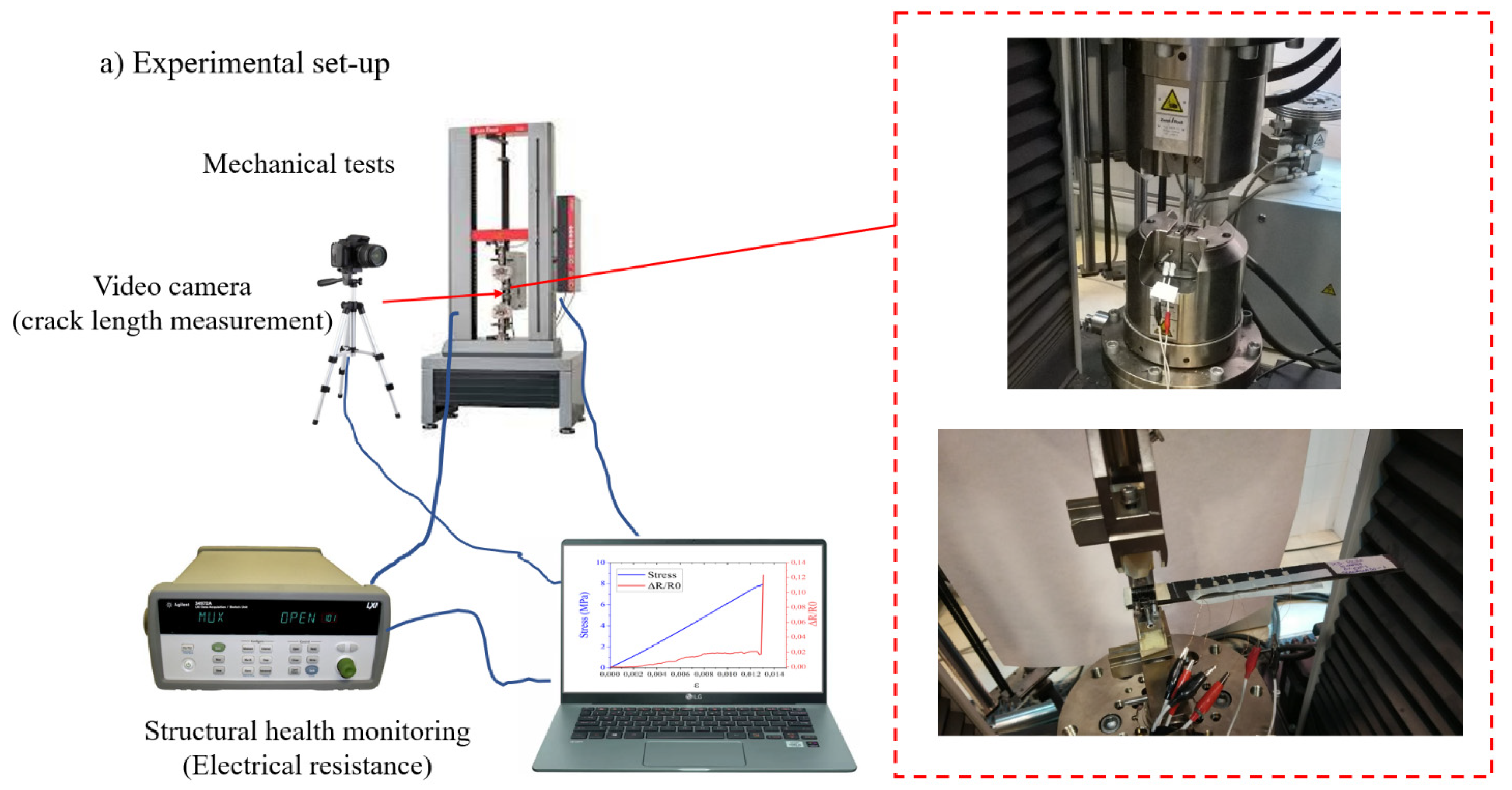
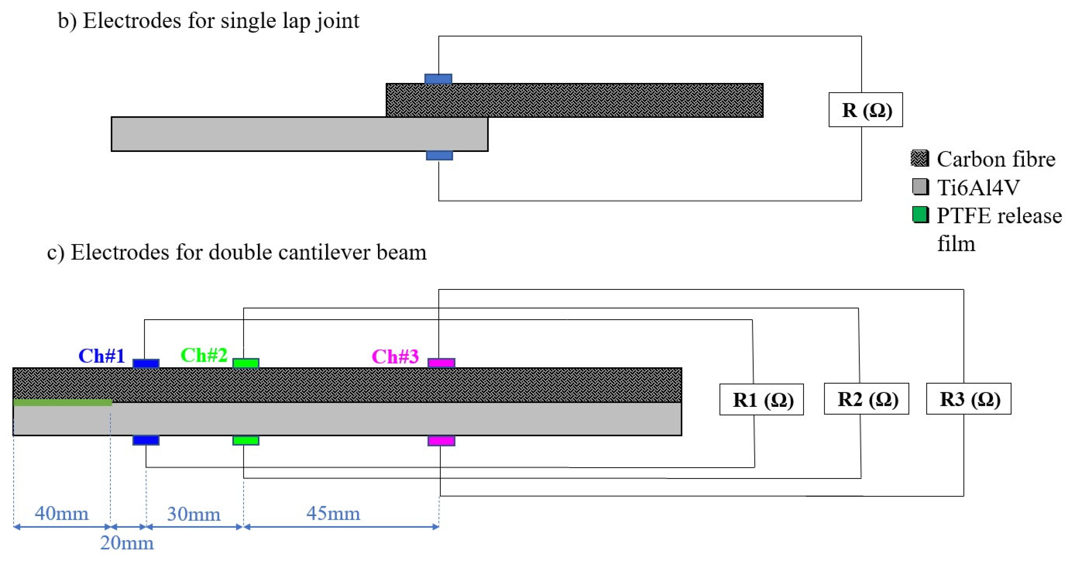
2.3.4. Structural Health Monitoring (SHM)
3. Results
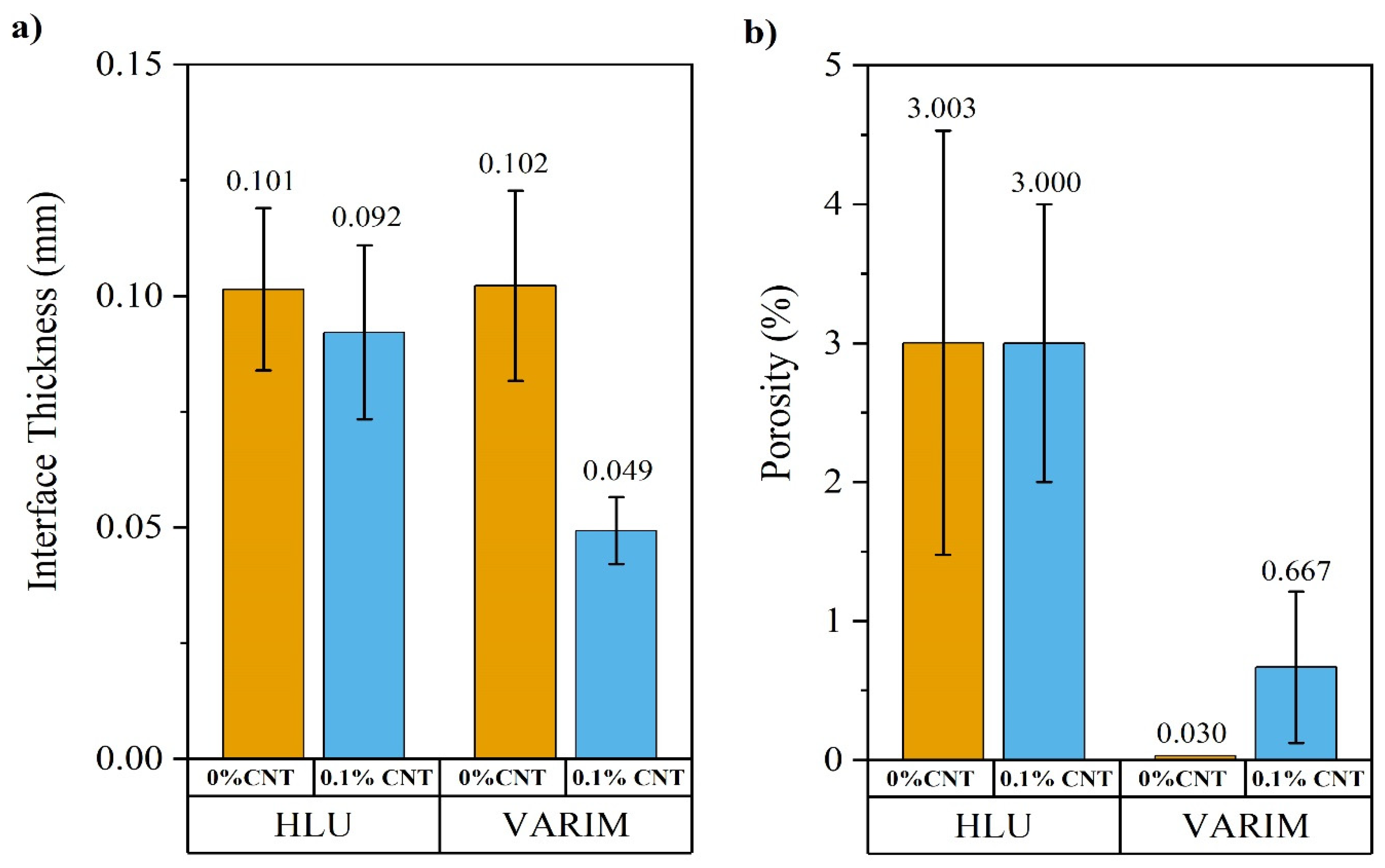
3.1. Optical Microscopy and Image Analysis for Multi-Material Joint Quality
3.2. Mechanical Properties
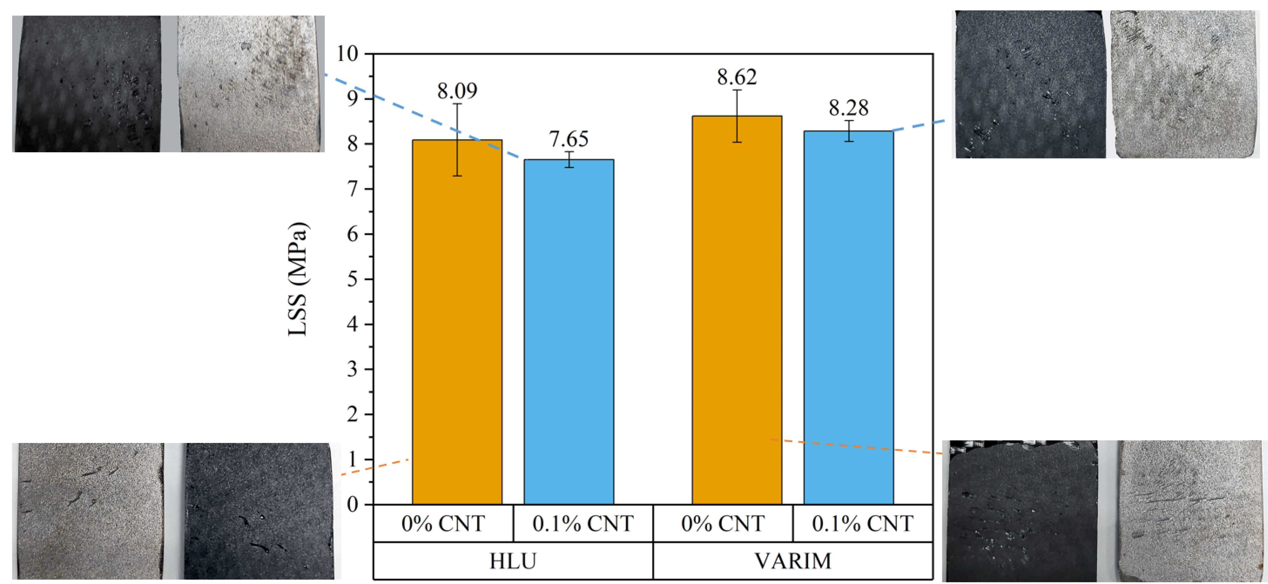
3.2.1. Influence of Manufacturing Process on Lap Shear Stress
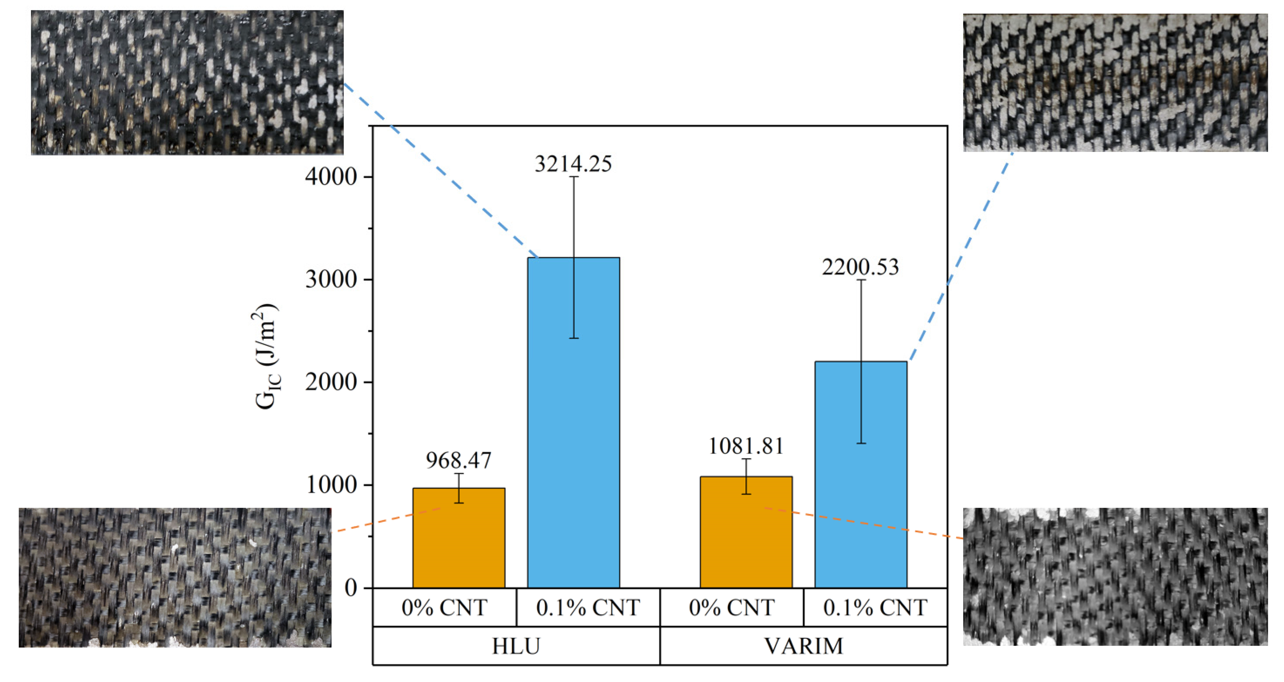
3.2.2. Influence of Manufacturing Process on Fracture Energy
3.3. Influence on Structural Health Monitoring (SHM)
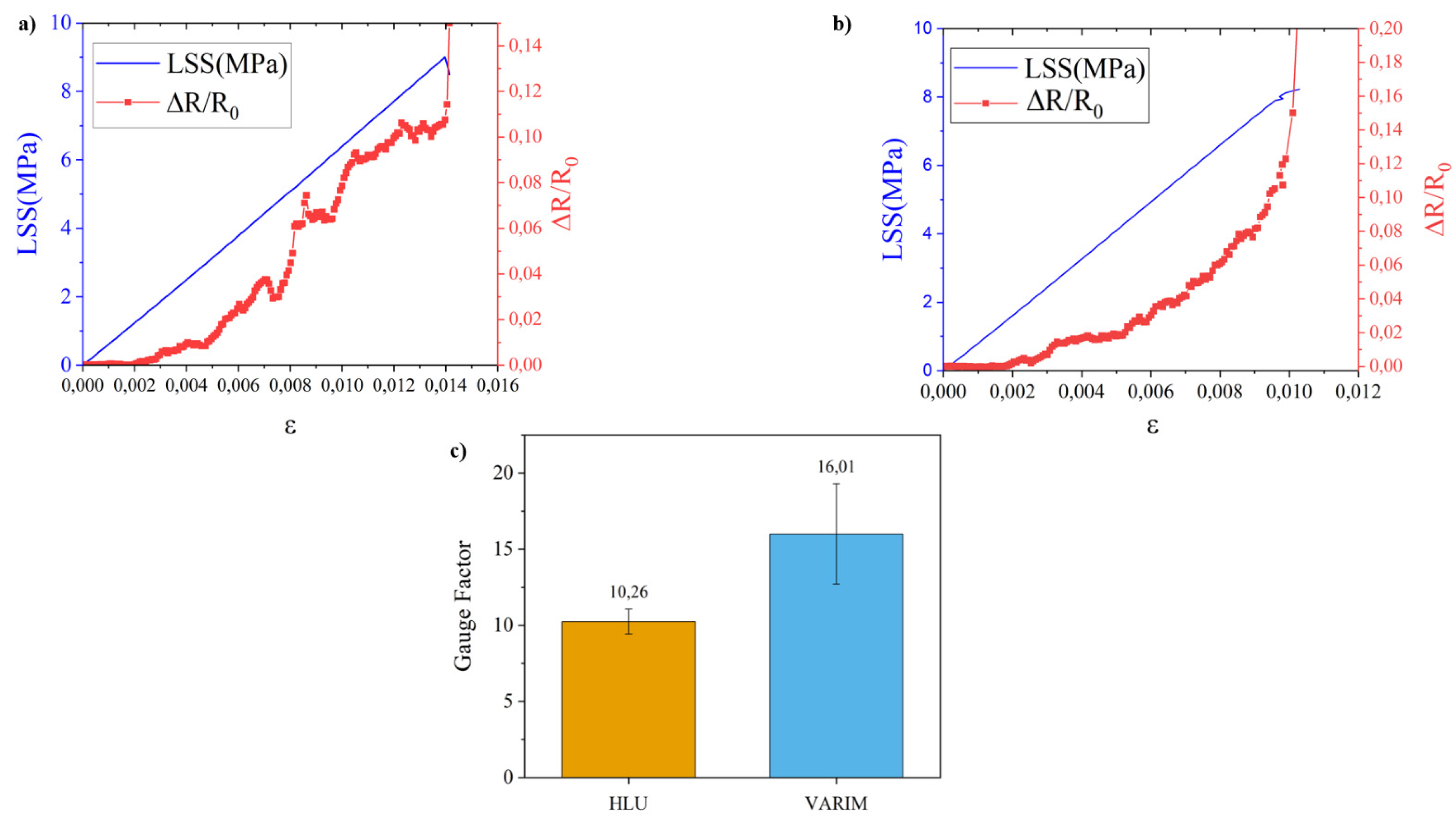
3.3.1. Influence of Manufacturing Process on SHM of Lap Shear Stress Test
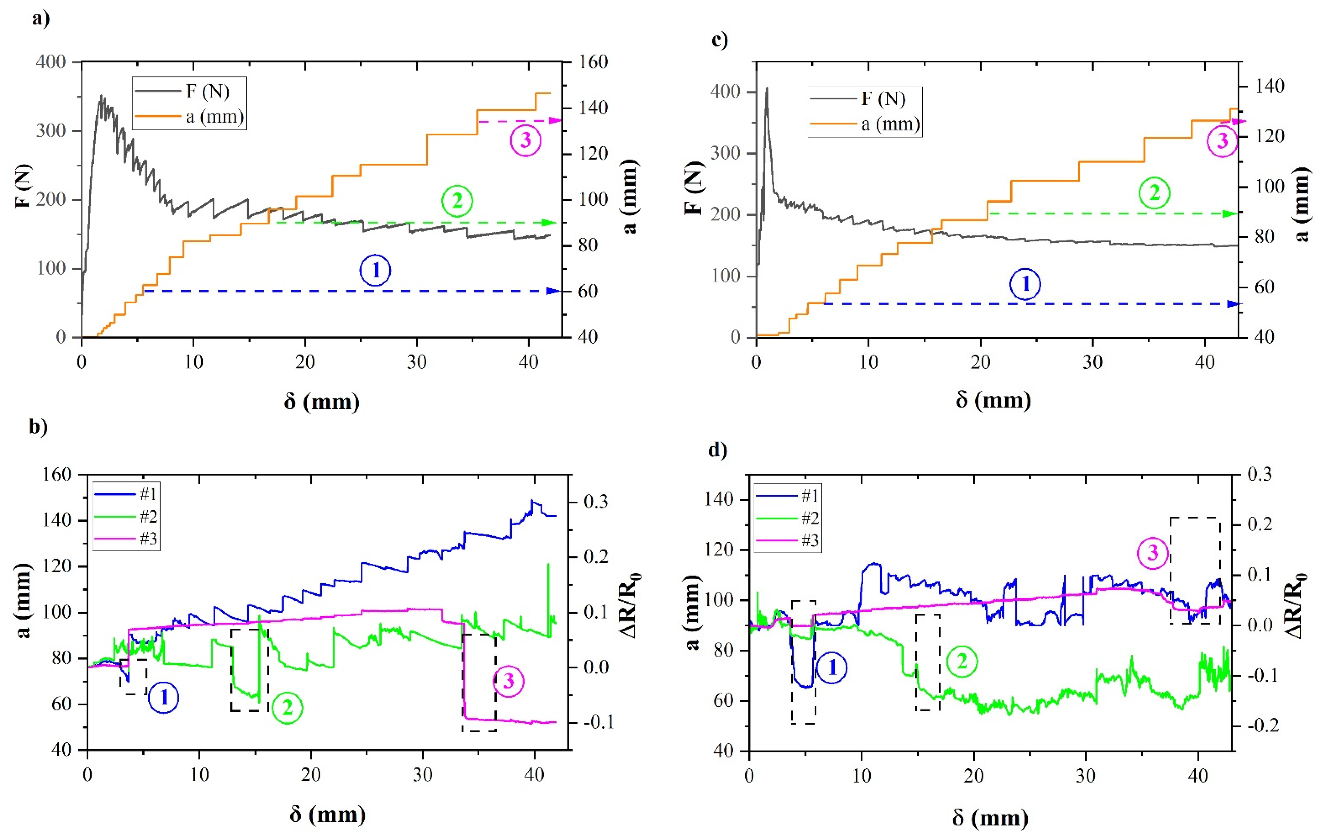
3.3.2. Influence of Manufacturing Process on SHM of Fracture Energy-Mode I Tests
4. Conclusions
Author Contributions
Funding
Acknowledgments
Conflicts of Interest
References
- Kostopoulos, V.; Masouras, A.; Baltopoulos, A.; Vavouliotis, A.; Sotiriadis, G.; Pambaguian, L. A critical review of nanotechnologies for composite aerospace structures. CEAS Space J. 2017, 9, 35–57. [Google Scholar] [CrossRef]
- Zhou, H.W.; Mishnaevsky, L.; Yi, H.Y.; Liu, Y.Q.; Hu, X.; Warrier, A.; Dai, G.M. Carbon fiber/carbon nanotube reinforced hierarchical composites: Effect of CNT distribution on shearing strength. Compos. Part B Eng. 2016, 88, 201–211. [Google Scholar] [CrossRef] [Green Version]
- Wicks, S.S.; Wang, W.; Williams, M.R.; Wardle, B.L. Multi-scale interlaminar fracture mechanisms in woven composite laminates reinforced with aligned carbon nanotubes. Compos. Sci. Technol. 2014, 100, 128–135. [Google Scholar] [CrossRef]
- Truong, H.T.; Lagoudas, D.C.; Ochoa, O.O.; Lafdi, K. Fracture toughness of fiber metal laminates: Carbon nanotube modified Ti–polymer–matrix composite interface. J. Compos. Mater. 2014, 48, 2697–2710. [Google Scholar] [CrossRef]
- Lin, Y.; Gigliotti, M.; Lafarie-Frenot, M.C.; Bai, J.; Marchand, D.; Mellier, D. Experimental study to assess the effect of carbon nanotube addition on the through-thickness electrical conductivity of CFRP laminates for aircraft applications. Compos. Part B Eng. 2015, 76, 31–37. [Google Scholar] [CrossRef]
- Sánchez-Romate, X.F.; Baena, L.; Jiménez-Suárez, A.; Sánchez, M.; Güemes, A.; Ureña, A. Exploring the mechanical and sensing capabilities of multi-material bonded joints with carbon nanotube-doped adhesive films. Compos. Struct. 2019, 229, 111477. [Google Scholar] [CrossRef]
- Joshi, S.C.; Dikshit, V. Enhancing interlaminar fracture characteristics of woven CFRP prepreg composites through CNT dispersion. J. Compos. Mater. 2012, 46, 665–675. [Google Scholar] [CrossRef]
- Zhang, H.; Liu, Y.; Kuwata, M.; Bilotti, E.; Peijs, T. Improved fracture toughness and integrated damage sensing capability by spray coated CNTs on carbon fibre prepreg. Compos. Part Appl. Sci. Manuf. 2015, 70, 102–110. [Google Scholar] [CrossRef]
- Kumar, V.; Sharma, S.; Pathak, A.; Singh, B.P.; Dhakate, S.R.; Yokozeki, T.; Okada, T.; Ogasawara, T. Interleaved MWCNT buckypaper between CFRP laminates to improve through-thickness electrical conductivity and reducing lightning strike damage. Compos. Struct. 2019, 210, 581–589. [Google Scholar] [CrossRef]
- Gaztelumendi, I.; Chapartegui, M.; Seddon, R.; Flórez, S.; Pons, F.; Cinquin, J. Enhancement of electrical conductivity of composite structures by integration of carbon nanotubes via bulk resin and/or buckypaper films. Compos. Part B Eng. 2017, 122, 31–40. [Google Scholar] [CrossRef]
- Veedu, V.P.; Cao, A.; Li, X.; Ma, K.; Soldano, C.; Kar, S.; Ajayan, P.M.; Ghasemi-Nejhad, M.N. Multifunctional composites using reinforced laminae with carbon-nanotube forests. Nat. Mater. 2006, 5, 457–462. [Google Scholar] [CrossRef] [PubMed]
- Studer, J.; Keller, A.; Leone, F.; Stefaniak, D.; Dransfeld, C.; Masania, K. Local reinforcement of aerospace structures using co-curing RTM of metal foil hybrid composites. Prod. Eng. 2018, 12, 195–201. [Google Scholar] [CrossRef]
- Fink, A.; Camanho, P.P.; Andrés, J.M.; Pfeiffer, E.; Obst, A. Hybrid CFRP/titanium bolted joints: Performance assessment and application to a spacecraft payload adaptor. Compos. Sci. Technol. 2010, 70, 305–317. [Google Scholar] [CrossRef]
- Alderliesten, R.C.; Benedictus, R. Fiber/Metal Composite Technology for Future Primary Aircraft Structures. J. Aircr. 2008, 45, 1182–1189. [Google Scholar] [CrossRef]
- Molitor, P.; Barron, V.; Young, T. Surface treatment of titanium for adhesive bonding to polymer composites: A review. Int. J. Adhes. Adhes. 2001, 21, 129–136. [Google Scholar] [CrossRef]
- Wang, W.; Poulis, J.A.; Freitas ST, D.; Zarouchas, D. Surface pretreatments on CFRP and Titanium for manufacturing adhesively bonded bi-material joints. In Proceedings of the ECCM18—18th European Conference on Composite Materials, Athens, Greece, 25–28 June 2018; Volume 9. [Google Scholar]
- Blohowiak, K.Y.; Anderson, R.A.; Stephenson, R.R. Structural Technology and Analysis Program (STAP). Delivery Order 0010: Sol-Gel Technology for Surface Preparation of Metal Alloys for Adhesive Bonding and Sealing Operations (BOEING CO SEATTLE WA PHANTOM WORKS.).
- Jiménez-Suárez, A.; Campo, M.; Sánchez, M.; Romón, C.; Ureña, A. Dispersion of carbon nanofibres in a low viscosity resin by calendering process to manufacture multiscale composites by VARIM. Compos. Part B Eng. 2012, 43, 3104–3113. [Google Scholar] [CrossRef]
- Da Silva, L.F.M.; Rodrigues, T.N.S.S.; Figueiredo, M.A.V.; de Moura, M.F.S.F.; Chousal, J.A.G. Effect of Adhesive Type and Thickness on the Lap Shear Strength. J. Adhes. 2006, 82, 1091–1115. [Google Scholar] [CrossRef]
- Gleich, D.M.; Tooren, M.J.L.V.; Beukers, A. Analysis and evaluation of bondline thickness effects on failure load in adhesively bonded structures. J. Adhes. Sci. Technol. 2001, 15, 1091–1101. [Google Scholar] [CrossRef]
- Mall, S.; Ramamurthy, G. Effect of bond thickness on fracture and fatigue strength of adhesively bonded composite joints. Int. J. Adhes. Adhes. 1989, 9, 33–37. [Google Scholar] [CrossRef]
- Carlberger, T.; Stigh, U. Influence of Layer Thickness on Cohesive Properties of an Epoxy-Based Adhesive—An Experimental Study. J. Adhes. 2010, 86, 816–835. [Google Scholar] [CrossRef]
- Jiménez-Suárez, A.; Campo, M.; Sánchez, M.; Romón, C.; Ureña, A. Influence of the functionalization of carbon nanotubes on calendering dispersion effectiveness in a low viscosity resin for VARIM processes. Compos. Part B Eng. 2012, 43, 3482–3490. [Google Scholar] [CrossRef]
- Prolongo, S.G.; Rosario, G.D.; Ureña, A. Coupled thermal-electrical analysis of carbon nanotube/epoxy composites. Polym. Eng. Sci. 2013, 54, 1976–1982. [Google Scholar] [CrossRef]
- Jiménez-Suárez, A.; Campo, M.; Gaztelumendi, I.; Markaide, N.; Sánchez, M.; Ureña, A. The influence of mechanical dispersion of MWCNT in epoxy matrix by calendering method: Batch method versus time controlled. Compos. Part B Eng. 2013, 48, 88–94. [Google Scholar] [CrossRef]
- Thostenson, E.T.; Chou, T.-W. Processing-structure-multi-functional property relationship in carbon nanotube/epoxy composites. Carbon 2006, 44, 3022–3029. [Google Scholar] [CrossRef]
- Shah, O.R.; Tarfaoui, M. Effect of adhesive thickness on the Mode I and II strain energy release rates. Comparative study between different approaches for the calculation of Mode I & II SERR’s. Compos. Part B Eng. 2016, 96, 354–363. [Google Scholar]
- Streitferdt, A.; Rudolph, N.; Taha, I. Co-Curing of CFRP-Steel Hybrid Joints Using the Vacuum Assisted Resin Infusion Process. Appl. Compos. Mater. 2017, 24, 1137–1149. [Google Scholar] [CrossRef]
- Sadeghian, R.; Gangireddy, S.; Minaie, B.; Hsiao, K.-T. Manufacturing carbon nanofibers toughened polyester/glass fiber composites using vacuum assisted resin transfer molding for enhancing the mode-I delamination resistance. Compos. Part Appl. Sci. Manuf. 2006, 37, 1787–1795. [Google Scholar] [CrossRef]
- Rachmadini, Y.; Tan VB, C.; Tay, T.E. Enhancement of Mechanical Properties of Composites through Incorporation of CNT in VARTM—A Review. J. Reinf. Plast. Compos. 2010, 29, 2782–2807. [Google Scholar] [CrossRef]
- Thostenson, E.T.; Chou, T.-W. Real-time in situ sensing of damage evolution in advanced fiber composites using carbon nanotube networks. Nanotechnology 2008, 19, 215713. [Google Scholar] [CrossRef]
- Sánchez, M.; Moriche, R.; Prolongo, S.G.; Marrón, A.R.; Jiménez-Suárez, A.; Ureña, A. Evaluation of sensitivity for detecting different failure modes of epoxy matrix composites doped with graphene nanoparticles. Compos. Struct. 2019, 225, 111167. [Google Scholar] [CrossRef]


| Neat Resin | CNT Doped Resin | |
|---|---|---|
| HLU |  |  |
| VARIM |  |  |
| HLU | VARIM | |
|---|---|---|
| R0 (Ω) | 12.51 ±2.1 | 1.19 ± 0.35 |
| GIC | 3214 ± 788 | 2200 ± 796 |
| ΔR/R0 | 1.20 ± 0.26 | 0.97 ± 0.35 |
Publisher’s Note: MDPI stays neutral with regard to jurisdictional claims in published maps and institutional affiliations. |
© 2021 by the authors. Licensee MDPI, Basel, Switzerland. This article is an open access article distributed under the terms and conditions of the Creative Commons Attribution (CC BY) license (https://creativecommons.org/licenses/by/4.0/).
Share and Cite
Dasilva, S.; Jimenez-Suarez, A.; Rodríguez, E.; Prolongo, S.G. Influence of Manufacturing Process in Structural Health Monitoring and Mechanical Behaviour of CNT Reinforced CFRP and Ti6Al4V Multi-Material Joints. Polymers 2021, 13, 2488. https://doi.org/10.3390/polym13152488
Dasilva S, Jimenez-Suarez A, Rodríguez E, Prolongo SG. Influence of Manufacturing Process in Structural Health Monitoring and Mechanical Behaviour of CNT Reinforced CFRP and Ti6Al4V Multi-Material Joints. Polymers. 2021; 13(15):2488. https://doi.org/10.3390/polym13152488
Chicago/Turabian StyleDasilva, S., A. Jimenez-Suarez, E. Rodríguez, and S. G. Prolongo. 2021. "Influence of Manufacturing Process in Structural Health Monitoring and Mechanical Behaviour of CNT Reinforced CFRP and Ti6Al4V Multi-Material Joints" Polymers 13, no. 15: 2488. https://doi.org/10.3390/polym13152488