Article

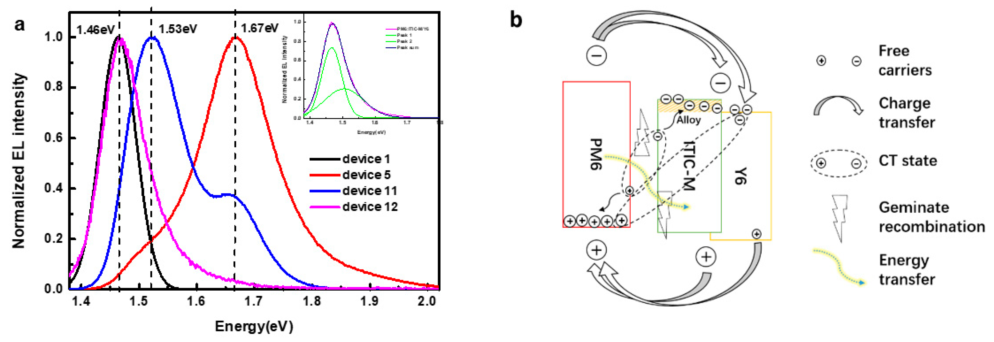
Synergetic Effect of Different Carrier Dynamics in Pm6:Y6:ITIC-M Ternary Cascade Energy Level System

1
Key Laboratory of Luminescence and Optical Information, Beijing Jiaotong University, Ministry of Education, Bejjing 100044, China
2
Department of Physics, Faculty of Science, King Abdulaziz University, Jeddah 21589, Saudi Arabia
*
Authors to whom correspondence should be addressed.
Polymers 2021, 13(15), 2398; https://doi.org/10.3390/polym13152398
Submission received: 29 June 2021 / Revised: 12 July 2021 / Accepted: 12 July 2021 / Published: 22 July 2021
(This article belongs to the Topic Multiple Application for Novel and Advanced Materials)

Abstract

:
Although reported ternary polymer solar cells have higher power conversion efficiency than binary polymers, the mechanism of exciton separation and charge transport in this complex ternary system is still unclear. Herein, based on PM6:Y6:ITIC-M ternary solar cells, we combine the technique of luminescence spectroscopy, including electroluminescence (EL) and photoluminescence (PL) with photovoltaic measurements, to understand clearly the detailed roles of ITIC-M as the third component in the contribution of device performance. The results show that ITIC-M can form the alloy-like composite with Y6 but leave individual Y6 acceptor to conduct charge transfer with PM6 donor, which improves Voc but decreases Jsc because of poor charge transfer capacity of ITIC-M. Meanwhile, the energy transfer from PM6 to ITIC-M exists in the active layers; small IE suppresses exciton dissociation. Deteriorating performance of solar cells demonstrates that, except for complementary absorption spectrum and suitable energy levels in PM6:Y6:ITIC-M system, the synergetic effects of carrier dynamics among different organic materials play an important role in influencing the performance of ternary solar cells.

1. Introduction

The development of sustainable energy can help alleviate the energy crisis and environmental problems. In particular, organic solar cells (OSCs), as a kind of strong candidate for the new energy sources, have attracted much attention due to their low cost, light weight, mechanical flexibility, translucency, fast roll-to-roll printing method and non-toxicity [1,2,3,4]. So far, many strategies have been developed to improve the performance of OSCs, such as the synthesis of high-efficiency photoelectric materials [5,6], optimization of blend film morphology [7], tandem cell approach [8] and so on. Therein, ternary organic solar cells (TOSCs) have an active layer composed of three light-collecting materials with a wide complementary range of light absorption similar to tandem cells but with a simple structure design which makes them attract widespread attention [9,10,11]. The working mechanism of TOSCs is summarized as charge transfer, energy transfer or as parallel-connected tandem cells. The charge can be transferred from the original materials to the add-on component or from the add-on component to the original materials or between the original materials [11,12,13]. If the charge transfer network is independently in TOSCs [14], TOSCs work the same as parallel-connected tandem cells. For energy transfer, it includes a long-distance Forster resonance energy transfer (FRET) and a short-distance Dexter energy transfer among three components [15,16]. In recent years, the non-fullerene acceptors (NFA) have been widely used in TOSCs, which exhibit great potential in providing morphological advantages, reducing energy loss and expanding absorption range [17,18]. In particular, it was reported that TOSCs based on NFAs achieved a record power conversion efficiency (PCE) of 17.6% [19]. Peng’s group reported that in PBDB-T: PTB7-Th: SFBRCN ternary solar cells, there exist multiple energy transfer pathways from PBDB-T to PTB7-Th, and from SFBRCN to the above two polymer donors [20]. Chen’s group reported a new non-fullerene acceptor named BTP-M as the third component for the PM6:Y6 binary system, where an alloy-like composite is formed between Y6 and BTP-M [21]. Ge et al. reported a non-fullerene acceptor DTF-IC as the third component in the PBDB-T:IT-M system, which is able to provide a cascading energy level between host donor and acceptor to improve charge transfer [22]. Different carrier dynamics are mentioned in many previous reports. However, the synergetic effect of different carrier dynamics in TOSCs is rarely mentioned but it is very important to affect the efficiency of TOSCs.
In this article, we fabricated various ternary cell devices by incorporating ITIC-M (3,9-bis((Z)-1-(6-(dicyanomethylene)-2-methyl-5,6-dihydro-6H-cyclopenta[b]thiophen-6-one-5-yl)ethylene)-5,5,11,11-tetrakis(4-hexylphenyl)dithieno [2,3-d:2′,3′-d′]-sindaceno [1,2-b:5,6-b′]dithiophene), an NFA as the additional acceptor material into (poly[(2,6-(4,8-bis(5-(2-ethylhexyl-3-fleoro)thiophen-2-yl)-benzo[1,2-b:4,5-b′]dithiophene))-alt-(5,5-(1′,3′-di-2-thienyl-5′,7′-bis(2-ethylhexyl)benzo[1′,2′-c:4′,5′-c′]dithiophene-4,8-dione)]) PM6:Y6 (2,20-((2Z,20Z)-((12,13-bis(2-ethylhexyl)-3,9-diundecyl-12,13-dihydro-[1,2,5]thiadiazolo[3,4-e]thieno[2″,30′:4′,50]thieno[20,30:4,5]pyrrolo[3,2-g]thieno[20,30:4,5]thieno[3,2-b]indole-2,10-diyl)bis(methanylylidene))bis(5,6-difluoro-3-oxo-2,3-dihydro-1H-indene-2,1-diylidene))dimalononitrile) host blend films. The ITIC-M shows an absorption spectrum from 500 nm to 800 nm and forms the complementary absorption spectrum with PM6 and Y6, finally increasing the photon harvesting of solar cells. Besides, the highest occupied molecular orbital (HOMO) energy level and the lowest unoccupied molecular orbital (LUMO) energy level of ITIC-M are both located between that of PM6 and Y6, respectively, and Y6 and ITIC-M form an alloy acceptor to improve the open circuit voltage (Voc). However, lower short circuit current (Jsc) and fill factor (FF) occur in ternary solar cells, which is contrary to the improved absorption. To account for the mechanism of carrier dynamics in ternary solar cells, EL spectroscopy as a simple measurement was utilized to analyze the carrier recombination by combining with PL spectroscopy. It is demonstrated that electrons will accumulate in the alloy acceptor because of the synergy between inefficient extraction and decreased exciton dissociation in ternary solar cells. Consequently, the increasing recombination leads to a decrease of Jsc and FF.

2. Materials and Methods

Materials: PM6, Y6, ITIC-M and PDINO were purchased from Solarmer Energy Inc., China, Beijing and used as received. Chloroform (CF) and 1, 8-diiodooctane (DIO) were commercially procured from Sigma-Aldrich, USA, Shanghai branch with purity greater than 99.9% and 98.0%, respectively.
Solution preparation and device fabrication: According to the previous report [23], a 16 mg mL−1 PM6:Y6 solution with a weight ratio of 1:1.2 (w/w) and ternary solutions mixed as blend were prepared in CF and then heated and stirred at 45 °C for 3 h. Next, 0.5 v% DIO as additive was added into dissolved solutions an hour before spin coating the active layer. PDINO was mixed into methyl alcohol with concentration of 1 mg mL−1. Ternary solar cells were fabricated in two batches by using the conventional structure of ITO/PEDOT: PSS/active layer film/PDINO/Ag, as shown in Figure 1a.
As the solutions for ternary devices, in one batch, the polymer donor to the acceptor ratio was kept constant as 1:1.2 and the ratio of Y6 to ITIC-M was changed. In another batch, the ratio of PM6 to Y6 was kept as 1:1.2, and the content of ITIC-M in the bulk-heterojunction (BHJ) was changed. The prepared active layer films and corresponding devices are as follows:
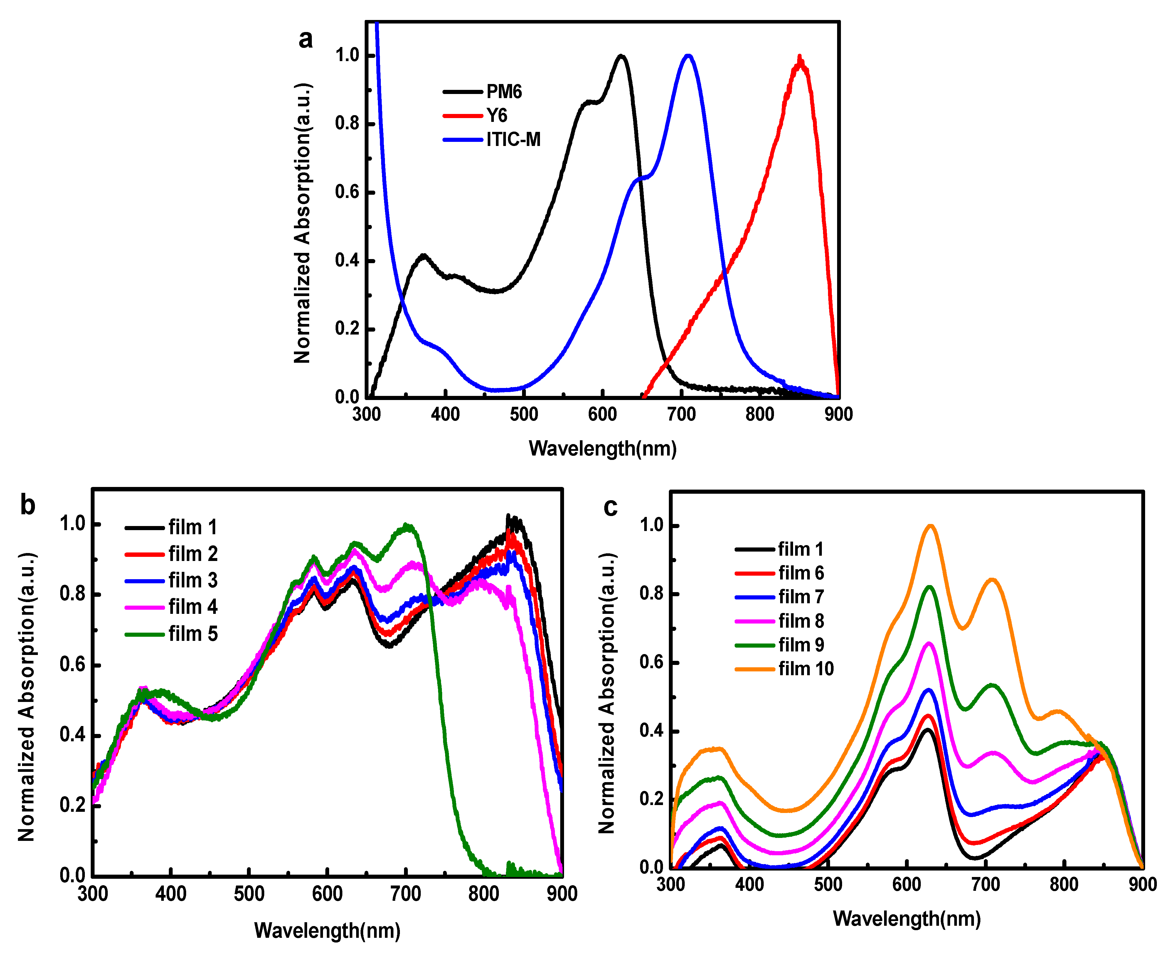
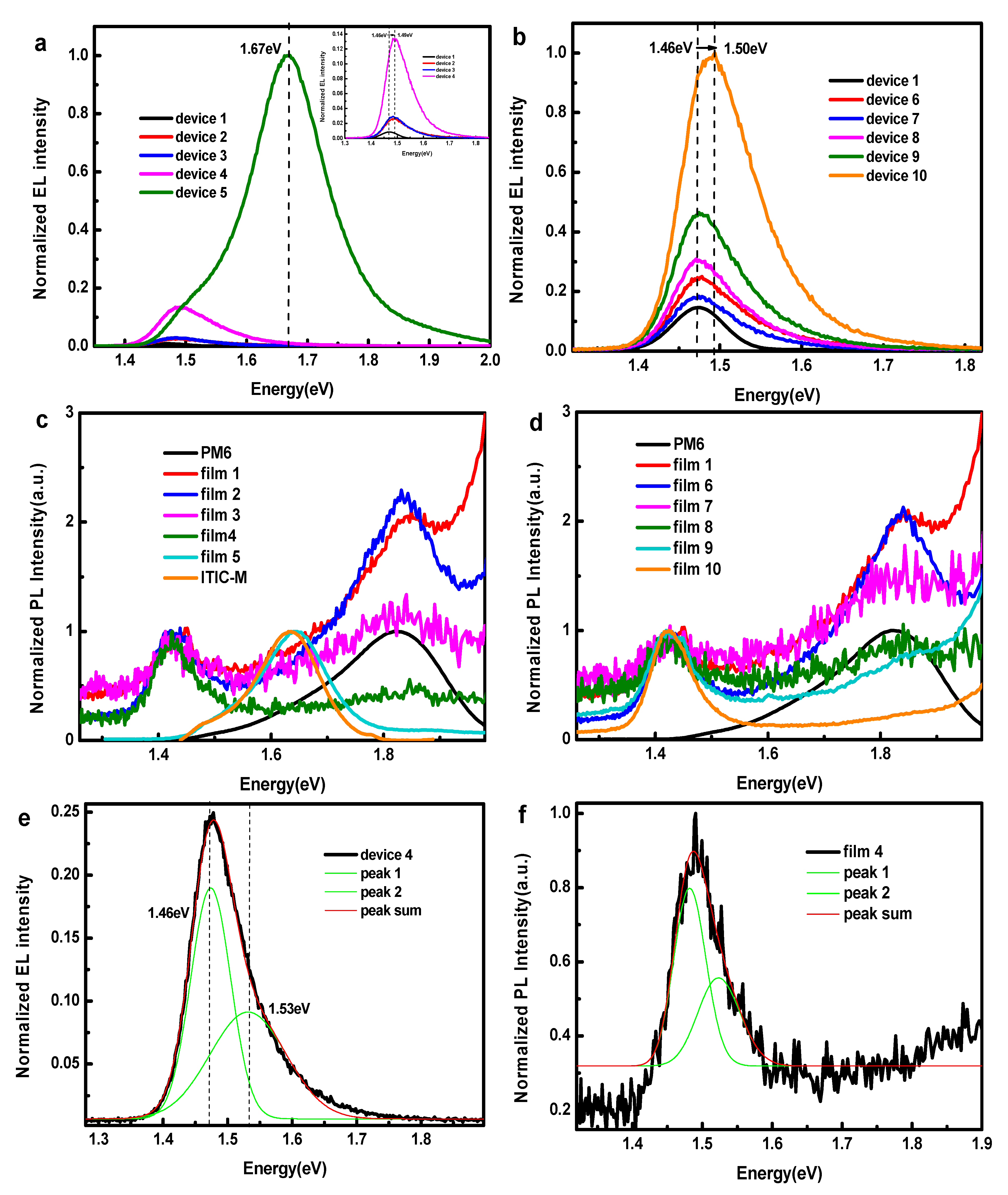
  • Film 1: PM6: Acceptor (Y6:ITIC-M = 1:0) = 1:1.2
  • Film 2: PM6: Acceptor (Y6:ITIC-M = 0.9:0.1) = 1:1.2
  • Film 3: PM6: Acceptor (Y6:ITIC-M = 0.8:0.2) = 1:1.2
  • Film 4: PM6: Acceptor (Y6:ITIC-M = 0.6:0.4) = 1:1.2
  • Film 5: PM6: Acceptor (Y6:ITIC-M = 0:1) = 1:1.2
  • Film 6: PM6:Y6:ITIC-M = 1:1.2:0.1
  • Film 7: PM6:Y6:ITIC-M = 1:1.2:0.2
  • Film 8: PM6:Y6:ITIC-M = 1:1.2:0.4
  • Film 9: PM6:Y6:ITIC-M = 1:1.2:0.6
  • Film 10: PM6:Y6:ITIC-M = 1:1.2: 1
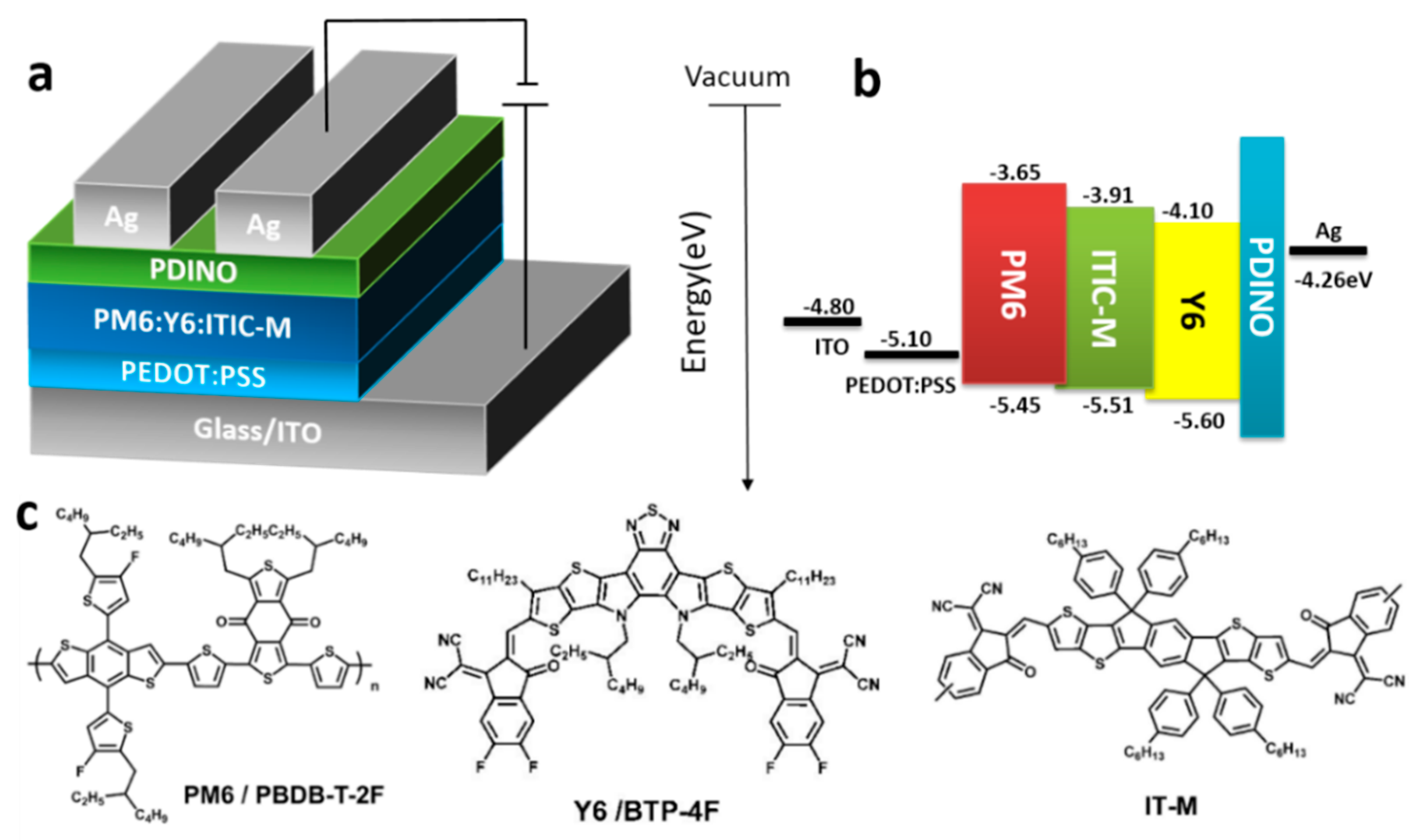
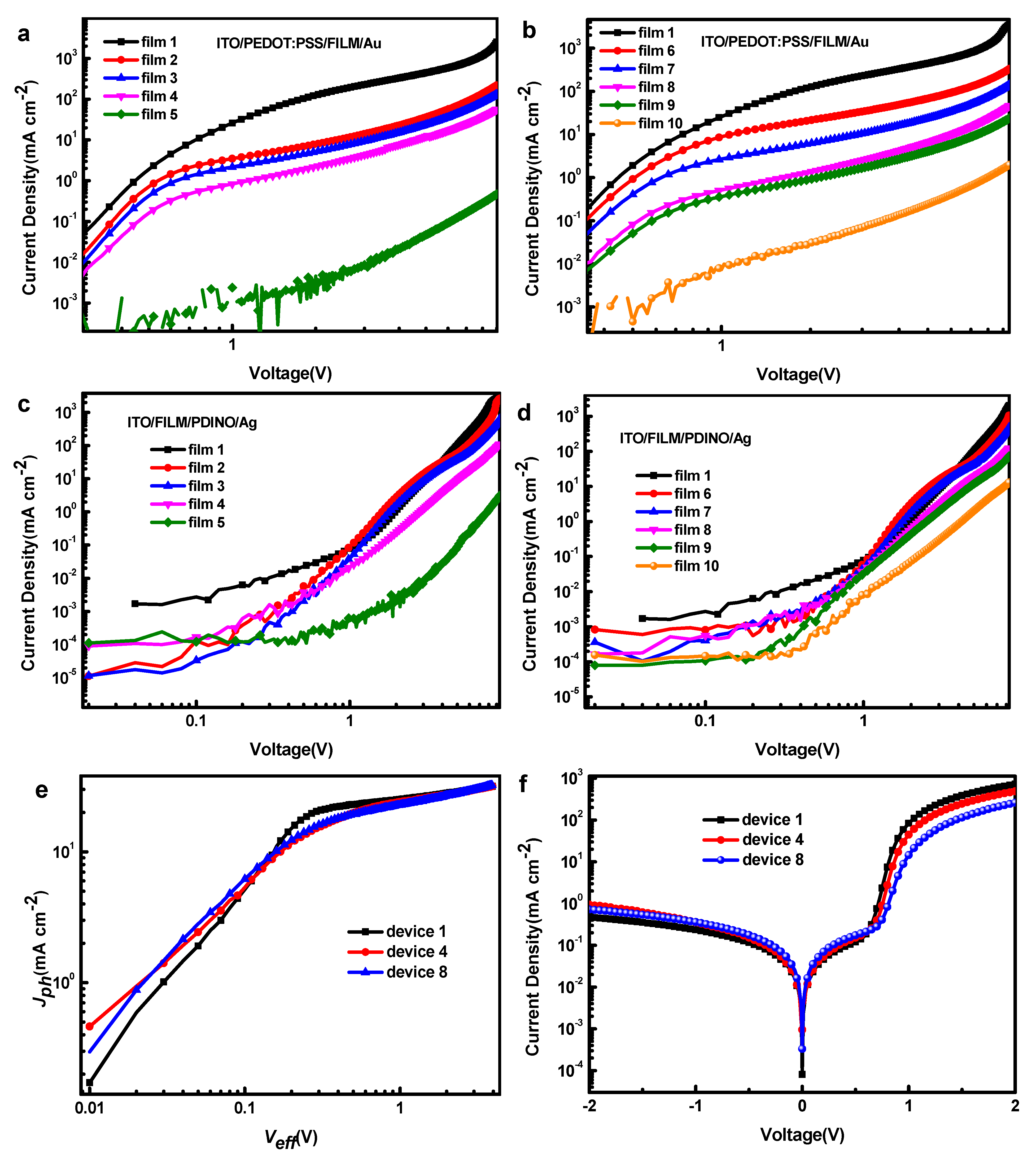
  • Device 1–10: ITO/PEDOT: PSS/film1–10/PDINO/Ag
First, indium tin oxide (ITO) coated glass substrates (sheet resistance of 15 ohm/square) were cleaned ultrasonically in a cleaning agent, deionized water and ethanol for 30 min, respectively, and then immediately blow-dried by high-density nitrogen, followed by plasma UV processing for 90 s. A highly conducting polymer PEDOT:PSS was spin coated onto the treated ITO substrates from an aqueous solution at 5000 rpm for 30 s, then these ITO coated with PEDOT:PSS were annealed at 150 °C for 10 min. Next, the solution used as active layer was prepared through spin coating at 3000 rpm for 30 s in N2-filling glove box and the prepared activity was annealed at 80 °C for 10 min and thoroughly dried in vacuum chamber for 1 h. After that, PDINO electron transport layer was spin coated on the active layer at 3000 rpm for 50 s. Finally, Ag cathodes (with the film thickness of 1000 Å) were deposited on the top at rate of 1.5 Å/s under a vacuum pressure of 2 × 10⁻⁴ Pa. The active area of solar cells is 4 mm2.
Measurement and characterization: The J-V characteristic curves of solar cells were measured with a Keithley 2400 source equipment unit under AM 1.5 G simulated solar illumination with an intensity of 100 mW cm−2. The EQE measurements were performed using a QE/IPCE Measurements Solar Cell Scan 100 (ZOLIX, Beijing, China) system equipped with calibrated silicon photodiode as the reference cell. PL spectra were acquired using a modified Horiba FL1000. EL spectra were performed by using Keithley 2410 to support bias and detectors in Horiba FL 1000. The UV−vis absorption spectrum was acquired on Shimadzu UV-3101 PC spectrometer. The surface morphology characteristics and 3D images were measured by atomic force measurement (AFM, MFP-3D Infinity).

3. Results and Discussion

The device structure and HOMO energy level and LUMO energy level of component materials used in devices are shown in Figure 1a,b, respectively. The molecular structures of the organic polymer donor PM6, non-fullerene acceptor Y6 and ITIC-M used as the photoactive layer are shown in Figure 1c. HOMO energy level (−5.58 eV) and LUMO energy level (−3.91 eV) of ITIC-M is between that of PM6 and Y6, respectively, which will form cascade energy level, as we expected.
The absorption spectra of pure films and D:A blend films were measured and the normalized absorption spectra are shown in Figure 2a–c. PM6 film exhibits wide photon harvesting range with a major absorption peak at 630 nm. Y6 and ITIC-M films show strong photon harvesting ability in long wavelength range with the absorption peak at 700 nm and 820 nm, respectively, showing obviously complementary absorption spectra. As shown in Figure 2b,c, incorporation of ITIC-M could help to absorb light between 550 nm and 800 nm.
Figure 3a,b show the current density voltage (J-V) characteristics of different devices under AM1.5G illumination with the intensity of 100 mW cm−2. Table 1 and Table 2 summarize the OPV parameters of all devices. Device 1 exhibits a PCE of 14.03% with a value of Jsc of 24.80 mA cm−2, Voc of 0.83 V and FF of 68.30%. Voc increases with the augment ratio of ITIC-M in acceptors from 0.83 V to 0.91 V (device 1 to device 4), and obtains the highest value of 1.02 V in PM6:ITIC-M binary solar cell (device 5). The same Voc increase (from 0.85 V to 0.91 V) can be observed in devices 6 to device 10, which is attributable to the alloy acceptor formed by Y6 and ITIC-M as shown in later discussion. However, Jsc and FF decrease sharply with addition of ITIC-M and finally the value of PCE decreases. We determined the shunt (Rsh) and series (Rs) resistances of these devices from their J-V curves (Table 1) to evaluate their bulk and interfacial resistances (Rs), as well as the leakage current and free carrier recombination in their BHJ (Rsh) of the devices. The values of Rs in devices incorporating ITIC-M are higher than PM6:Y6 binary device (device 1), implying more defects at the interfaces and within the BHJ blend films of these devices. Moreover, lower values of Rsh suggest higher degrees of free carrier recombination.
As external quantum efficiency (EQE) results show in Figure 3c,d, the EQE of device 2 and 3 is lower than that of device 1 from 665 nm to 900 nm and the EQE from 300 nm to 650 nm has no significant change. This means that photogenerated carriers corresponding to the absorption of PM6 are collected similarly in three devices. However, as the ratio of ITIC-M increases, the carriers generated by ITIC-M and PM6 decrease, even as their light absorption increases. This may be due to the fact that excitons formed in ITIC-M and PM6 cannot be dissociated at their interface or ITIC-M cannot transfer electrons effectively. In device 4, the EQE from 475 nm to 750 nm has an obvious drop while the EQE of device 5 declines more drastically. In devices 6, 7, 8 and 9, the EQE from 450 nm to 900 nm drops with increase of ITIC-M, but rises a little from 350 nm to 450 nm, which is consistent with the changing of the absorption spectrum. Besides, the EQE of device 10 from 500 nm to 900 nm decreases dramatically. These drops of EQE are contrary to the enhancement of light absorption (Figure 3). It can be speculated that the addition of ITIC-M suppresses the exciton generated by absorbing light between 525 nm and 850 nm to dissociate into free carriers or suppresses these free carriers to transfer to electrode.
The microscopic morphology of the active layer plays a decisive role in the generation and transmission of charges in devices [24,25]. In order to understand the physical mechanism of performance decrease, firstly, we investigated the effects of the third content ITIC-M on the morphology of the PM6:Y6 blend film. The surface and bulk morphologies of five blend films (film 1, 4, 5, 8, 10) as examples were characterized by tapping-mode atomic force microscopy (AFM), as shown in Figure 4. The root mean square roughness (RMS) of different blend films are 1.078 nm (film 1), 1.217 nm (film 4), 1.652 nm (film 5), 1.270 nm (film 8) and 1.507 nm (film 10). RMS values reveal that the surface of blend films become a little rougher by adding ITIC-M, which is plausible as larger phase segregation emerges by incorporating ITIC-M as well as can be observed in the phase separation of blend films from the phase images in Figure 4. The rather rough surface increases the interface resistance, which is not conductive to the charge transport and extraction, and the larger phase separation due to adding ITIC-M will reduce the exciton dissociation interface. To further investigate the effect of ITIC-M on the blend film, one-dimensional (1D) grazing incidence X-ray diffraction (GIXRD) was used in film 1, 4 and 8. As shown in Figure 4c, three films exhibit a weak diffraction peak at 1.72 Å−1 in the out-of-plane direction, which corresponds to that of PM6. The almost identical locating at the same position and same intensity of GIXRD peak indicates that ITIC-M generates nearly no difference in polymer (PM6) crystallinity.
According to the above results, the carrier dynamic inside devices has changed after the addition of ITIC-M and the new carrier dynamic leads to a decreasing performance. To further understand the charge separation and charge transport process in ternary devices, we used EL spectrometry to study the exciton decay way and the charge transfer states (CTSs) of devices. The EL spectra of devices with different content of ITIC-M are shown in Figure 5a,b. The emission peak positions of CT states (ECT) vary in different devices; the ECT [26,27] becomes higher from 1.46 eV of device 1 to 1.49 eV of device 4, then locates at 1.67 eV in device 5 with the active layer PM6:ITIC-M. For device 6 to device 10 compared with device 1, ECT also changes from 1.46 eV to 1.50 eV with the increase of ITIC-M content. The changes of ECT indicate that it is plausible to consider Y6 and ITIC-M forming an alloy acceptor, and the ECT reaches maximum (1.67 eV) in PM6:ITIC-M binary device, which is consistent with the variation of Voc.
PL spectra were measured to further analyze the energy transfer mechanism in PM6:Y6:ITIC-M blend film excited by 550 nm as shown in Figure 5c,d. In the blend film of PM6:Y6 system, there are two peaks: 1.83 eV (678 nm) is from pure PM6 and 1.47 eV (846 nm) is from the recombination of CT states corresponding to the HOMO of PM6 and LUMO of Y6. Furthermore, in the blend film of PM6: ITIC-M, only one peak locates at 1.66 eV (746 nm), which corresponds to the recombination of CT states between HOMO of PM6 and LUMO of ITIC-M, and ITIC-M can almost quench PL of PM6. Although the large overlap of PM6 PL (678 nm) and ITIC-M absorption (700 nm) triggers efficient energy transfer from PM6 to Y6, the almost identical PL of CT state of PM6:ITIC-M with PL of ITIC-M means the HOMO of PM6 closes that of ITIC-M, which determines that the ionization energy (IE) is not enough to dissociate excitons in ITIC-M into free carriers by transferring holes from ITIC-M to PM6 efficiently [28]. The multiple peaks Gaussian fitting results in Figure 5e reveal that there are two peaks in EL spectroscopy of ternary solar cells, one is at 1.46 eV and another is at 1.53 eV, and the multiple peaks Gaussian fitting results of PL spectroscopy in Figure 5f are consistent with those of EL. Coexistence of EL peaks at 1.46 eV and 1.53 eV means that excitons can be dissociated in the interface of PM6:Y6 and between PM6 and Y6-ITIC-M alloy acceptor while the content of Y6 is larger than ITIC-M. However, in the PL spectra of ternary films, 1.67 eV (746 nm) corresponding to the CT emission of PM6:ITIC-M was missing, and the PL peak of PM6 decreased but the peak of CT states between PM6 and Y6 as well as between PM6 and Y6–ITIC-M alloy (shown in Figure 5e,f) increased along with the increasing content of ITIC-M. This means that increasing Y6- ITIC-M alloy is formed and helps to decrease excitons of PM6, but more carrier recombination [29] is the result at the interface of PM6 and Y6-ITIC-M alloy, which is one reason to cause low Jsc and FF. Therefore, it is concluded that by adding ITIC-M, even the exciton of PM6 is dissociated easily, but the recombination probability of CT states of PM6:Y6:ITIC-M increased, which may be due to the deterioration of charge transportation and increase of defect density.
To obtain more information of exciton separation and charge transfer mechanism in ternary films, we measured the EL spectra of devices by using the structure of ITO/PEDOT:PSS/PM6:Y6/ITIC-M/PDINO/Ag and ITO/PEDOT:PSS/PM6:ITIC-M/Y6/PDINO/Ag, named as device 11 and device 12, respectively, as shown in Figure 6a. The EL peak position of device 12 moves a little to the high-energy side compared with device 1, and the ECT emission of PM6:ITIC-M almost disappears. According to the result of multiple peaks Gaussian fitting (Figure 6a, inset), all ITIC-M form an alloy acceptor with Y6 and extra PM6:Y6 conduct charge transfer at their interface. In device 11, disappearance of EL peak located at 1.46 eV and appearance of the EL peaks located at 1.53 eV and at 1.67 eV indicate that carriers are recombined at the interface between PM6 and Y6:ITIC-M alloy acceptor and between PM6 and ITIC-M, which proves the bad electron transportation in ITIC-M. Combining EL results of device 11 with the other devices, it can be concluded that parts of ITIC-M and Y6 form an alloy acceptor and extra Y6 or ITIC-M could conduct charge transfer with PM6 alone.
In order to figure out the reason for recombination enhancement, the dark J-V characteristics of hole-only and electron-only devices were measured with the structure of ITO/PEDOT: PSS/active layer/Au and ITO/active layer/PDINO/Ag shown in Figure 7. The apparent charge carrier mobility of blend films is evaluated through the spare charge limit current (SCLC) method [30,31]. According to the Mott–Gurney law, the current density is given by (Equation (1)):
J = 9 ε 0 ε r μ V 2 / 8 L 3
where J is the current density, ε0 is the permittivity of free space, εr is the relative dielectric constant of the BHJ layer, μ is the charge carrier mobility, L is the thickness of the BHJ layer and V is the voltage drop across the device [32]. The computed results are shown in Table 3.
The hole mobility and the electron mobility of ternary devices incorporated with ITIC-M all decrease dramatically. In addition, the unbalance between hole and electron mobility would lead to the accumulation of carriers with the lower mobility in the device. This will result in an additional electric field which would hinder the extraction of carriers and increase the radiative recombination [33,34]. Then, the hole and electron trapping states of devices 1, 4 and 8 were calculated from J-V curves [35]. When the voltage goes beyond the kink point, it means that the trapping states are completely filled, and the trapping state density can be calculated by Equation (2):
V T F L = e n t L 2 2 ε 0 ε
where VTFL is the trap filled limit voltage, e is the elementary charge, L is the thickness of the active layer, ε is the relative dielectric constant of polymer (ε = 3), ε0 is the vacuum permittivity and nt is the trapping state density.
The electron and hole trapping states of devices 1, 4 and 8 are acquired as 1.77 × 1017 cm−3, 1.08 × 1017 cm−3 and 4.84 × 1016 cm−3 and 2.36 × 1016 cm−3, 4.13 × 1016 cm−3 and 2.07 × 1016 cm−3, respectively. The variation of hole trapping states is coherent with that of hole current that changes a little with the increasing of ITIC-M content. However, even the electron trapping state density decreases with the increasing of ITIC-M content in the active layer, but the electron current decreases dramatically. This means that the electron transport is going to be difficult in the active layer due to the adding of ITIC-M, which is proven by the lower electron mobility in ternary devices with increasing of ITIC-M. It also corresponds to the electroluminescence results detected in PM6:Y6:ITIC-M active layer.
Otherwise, we measured the photocurrent density (Jph) versus the effective voltage (Veff) curves for the devices 1, 4 and 8, plotted in Figure 7e. In principle, Jph is calculated according to [36,37]:
J p h = J L J D
where JL and JD represent current density under AM 1.5G illumination and in the dark, respectively. Veff is calculated according to [36,37]:
V e f f = V 0 V a
where V0 stands for the voltage at which Jph = 0 and Va is the applied voltage.
We can find that the Jph of three devices shows linear dependence on the voltage at a low Veff (<0.1 V), and rapidly reaches saturation at the high Veff (>1 V). It clearly shows that the devices 4 and 8 have a lower saturation photocurrent density (Jsat) than that of device 1. The charge dissociation probability P (E, T) of both devices determined by Jph/Jsat under short circuit condition is 89.11%, 84.27% and 84.69%, respectively. Combining P (E, T) and dark J-V curves (shown in Figure 7f), it is explicit that in PM6:Y6:ITIC-M ternary solar cells, ITIC-M suppresses exciton dissociation and increases recombination with decreasing of Jsc and FF.

4. Conclusions

In summary, we utilized ITIC-M as third content incorporated into PM6:Y6 to form ternary solar cells. Combining two simple measurement methods, EL spectroscopy and PL spectroscopy, it is demonstrated that there are different transfer mechanisms in PM6:Y6:ITIC-M ternary solar cells: (i) coexistence of EL peaks at 1.46 eV and 1.53 eV means that parts of ITIC-M and Y6 formed alloy acceptor while individual Y6 exists and conducts charge transfer with PM6 alone, (ii) large overlap of PM6 PL (678 nm) and ITIC-M absorption (700 nm) indicates existence of energy transfer from PM6 to ITIC-M. Small IE is adverse to exciton dissociation and unbalance of carrier mobility leads to accumulation of electrons, finally improving recombination. Except complementary absorption spectrum and suitable energy levels in PM6:Y6:ITIC-M system, carrier dynamics between organic materials play an important role in the performance of ternary solar cells.

Author Contributions

Conceptualization, Z.L. and S.Z.; methodology, Z.L. and S.Z.; software, D.S.; validation, S.Z., Z.X. and S.W.; formal analysis, A.A.A.-G.; investigation, Z.L.; writing—original draft preparation, Z.L. and X.H.; writing—review and editing, Z.L. and S.Z.; supervision, S.Z. and Z.X.; project administration, Z.X.; funding acquisition, B.Q. All authors have read and agreed to the published version of the manuscript.

Funding

This research was funded by the National Natural Science Foundation of China under Grant No. 61575019 and the Natural Science Foundation of Beijing under Grant No. 2192045.

Conflicts of Interest

The authors declare no conflict of interest.

References

  1. Duan, L.; Elumalai, N.K.; Zhang, Y.; Uddin, A. Progress in non-fullerene acceptor based organic solar cells. Sol. Energy Mater. Sol. Cells 2019, 193, 22–65. [Google Scholar] [CrossRef]
  2. Yan, C.; Rlow, S.B.; Wang, Z.; Yan, H.; Jen, A.; Marder, S.R.; Zhan, X. Non-fullerene acceptors for organic solar cells. Nat. Rev. Mater. 2018, 3, 18003. [Google Scholar] [CrossRef]
  3. Li, Y.; Xu, G.; Cui, C.; Li, Y. Flexible and semitransparent organic solar cells. Adv. Energy Mater. 2018, 8, 1701791. [Google Scholar] [CrossRef]
  4. Duan, L.; Uddin, A. Progress in stability of organic solar cells. Adv. Sci. 2020, 7, 1903259. [Google Scholar] [CrossRef] [PubMed] [Green Version]
  5. Liu, Q.; Jiang, Y.; Jin, K.; Qin, J.; Xu, J.; Li, W.; Xiong, J.; Liu, J.; Xiao, Z.; Sun, K.; et al. 18% efficiency organic solar cells. Sci. Bull. 2020, 65, 272–275. [Google Scholar] [CrossRef] [Green Version]
  6. Gasparini, N.; Salleo, A.; McCulloch, I.; Baran, D. The role of the third component in ternary organic solar cells. Nat. Rev. Mater. 2019, 4, 229–242. [Google Scholar] [CrossRef]
  7. Sun, R.; Guo, J.; Sun, C.; Wang, T.; Luo, Z.; Zhang, Z.; Jiao, X.; Tang, W.; Yang, C.; Li, Y.; et al. A universal layer-by-layer solution-processing approach for efficient non-fullerene organic solar cells. Energy Environ. Sci. 2019, 12, 384–395. [Google Scholar] [CrossRef]
  8. Meng, L.; Zhang, Y.; Wan, X.; Li, C.; Zhang, X.; Wang, Y.; Ke, X.; Xiao, Z.; Ding, L.; Xia, R. Organic and solution-processed tandem solar cells with 17.3% efficiency. Science 2018, 361, 1094–1098. [Google Scholar] [CrossRef] [Green Version]
  9. Ma, L.; Zhang, S.; Yao, H.; Xu, Y.; Wang, J.; Zu, Y.; Hou, J. High-efficiency nonfullerene organic solar cells enabled by 1000 nm thick active layers with a low trap-state density. ACS Appl. Mater. Interfaces 2020, 12, 18777–18784. [Google Scholar] [CrossRef] [PubMed]
  10. Zhao, C.; Wang, J.; Zhao, X.; Du, Z.; Yang, R.; Tang, J. Recent advances, challenges and prospects in ternary organic solar cells. Nanoscale 2021, 13, 2181–2208. [Google Scholar] [CrossRef] [PubMed]
  11. Huang, W.; Cheng, P.; Yang, Y.; Li, G.; Yang, Y. High-performance organic bulk-heterojunction solar cells based on multiple-donor or multiple-acceptor components. Adv. Mater. 2018, 30, 1705706. [Google Scholar] [CrossRef]
  12. Cheng, P.; Zhan, X. Versatile third components for efficient and stable organic solar cells. Mater. Horiz. 2015, 2, 462–485. [Google Scholar] [CrossRef]
  13. Li, H.; Lu, K.; Wei, Z. Polymer/small molecule/fullerene based ternary solar cells. Adv. Energy Mater. 2017, 7, 1602540. [Google Scholar] [CrossRef]
  14. Cheng, X.; Matthew, W.; Ping, D.; Yi, H.; Zhang, X.; Arafat, M.; Sun, K.; Baishakhi, U.M.; Faiazul, H.; Ashraf, U. Ternary blend organic solar cells with a non-fullerene acceptor as a third component to synergistically improve the efficiency. Org. Electron. 2018, 62, 261–268. [Google Scholar]
  15. Yang, L.; Yan, L.; You, W. Organic solar cells beyond one pair of donor–acceptor: Ternary blends and more. J. Phys. Chem. Lett. 2013, 4, 1802–1810. [Google Scholar] [CrossRef] [PubMed]
  16. Duan, L.; Zhang, Y.; Deng, R.; Yi, H.; Uddin, A. Balance between energy transfer and exciton separation in ternary organic solar cells with two conjugated polymer donors. ACS Appl. Energy Mater. 2020, 3, 5792–5803. [Google Scholar] [CrossRef]
  17. Chang, L.; Duan, L.; Sheng, M.; Yuan, J.; Yi, H.; Zou, Y.; Uddin, A. Optimising non-patterned moo3/ag/moo3 anode for high-performance semi-transparent organic solar cells towards window applications. Nanomaterials 2020, 10, 1759. [Google Scholar] [CrossRef]
  18. Hou, J.; Inganäs, O.; Friend, R.H.; Gao, F. Organic solar cells based on non-fullerene acceptors. Nat. Mater. 2018, 17, 119–128. [Google Scholar] [CrossRef]
  19. Ma, Q.; Jia, Z.; Meng, L.; Zhang, J.; Zhang, H.; Huang, W.; Yuan, J.; Gao, F.; Wan, Y.; Zhang, Z.; et al. Promoting charge separation resulting in ternary organic solar cells efficiency over 17.5%. Nano Energy 2020, 78, 105272. [Google Scholar] [CrossRef]
  20. Xu, X.; Bi, Z.; Ma, W.; Wang, Z.; Choy, W.C.; Wu, W.; Zhang, G.; Li, Y.; Peng, Q. Highly efficient ternary-blend polymer solar cells enabled by a nonfullerene acceptor and two polymer donors with a broad composition tolerance. Adv. Mater. 2017, 29, 1704271. [Google Scholar] [CrossRef] [PubMed]
  21. Zhan, L.; Li, S.; Lau, T.-K.; Cui, Y.; Lu, X.; Shi, M.; Li, C.-Z.; Li, H.; Hou, J.; Chen, H. Over 17% efficiency ternary organic solar cells enabled by two non-fullerene acceptors working in an alloy-like model. Energy Environ. Sci. 2020, 13, 635–645. [Google Scholar] [CrossRef]
  22. Wu, L.; Xie, L.; Tian, H.; Peng, R.; Huang, J.; Fanady, B.; Song, W.; Tan, S.; Bi, W.; Ge, Z. Efficient ternary organic solar cells based on a twin spiro-type non-fullerene acceptor. Sci. Bull. 2019, 64, 1087–1094. [Google Scholar] [CrossRef] [Green Version]
  23. Yuan, J.; Zhang, Y.; Zhou, L.; Zhang, G.; Yip, H.-L.; Lau, T.-K.; Lu, X.; Zhu, C.; Peng, H.; Johnson, P.A.; et al. Single-junction organic solar cell with over 15% efficiency using fused-ring acceptor with electron-deficient core. Joule 2019, 3, 1140–1151. [Google Scholar] [CrossRef]
  24. Zhou, W.; Chen, H.; Lv, J.; Chen, Y.; Zhang, W.; Yu, G.; Li, F. Improving the efficiency of polymer solar cells based on furan-flanked diketopyrrolopyrrole copolymer via solvent additive and methanol treatment. Nanoscale 2015, 7, 15945–15952. [Google Scholar] [CrossRef]
  25. Campoy-Quiles, M.; Ferenczi, T.A.M.; Agostinelli, T.; Etchegoin, P.G.; Kim, Y.; Anthopoulos, T.; Stavrinou, P.; Bradley, D.; Nelson, J. Morphology evolution via self-organization and lateral and vertical diffusion in polymer:Fullerene solar cell blends. Nat. Mater. 2008, 7, 158–164. [Google Scholar] [CrossRef] [PubMed]
  26. Wang, X.; Yang, Y.; He, Z.; Wu, H.; Cao, Y. Influence of the acceptor crystallinity on the open-circuit voltage in ptb7-th: Itic organic solar cells. J. Mater. Chem. C 2019, 7, 14861–14866. [Google Scholar] [CrossRef]
  27. Ullbrich, S.; Benduhn, J.; Jia, X.; Nikolis, V.C.; Tvingstedt, K.; Piersimoni, F.; Roland, S.; Liu, Y.; Wu, J.; Fischer, A.; et al. Emissive and charge-generating donor-acceptor interfaces for organic optoelectronics with low voltage losses. Nat. Mater. 2019, 18, 459–464. [Google Scholar] [CrossRef]
  28. Karuthedath, S.; Gorenflot, J.; Firdaus, Y.; Chaturvedi, N.; De Castro, C.S.P.; Harrison, G.T.; Khan, J.I.; Markina, A.; Balawi, A.H.; Pena, T.A.D.; et al. Intrinsic efficiency limits in low-bandgap non-fullerene acceptor organic solar cells. Nat. Mater. 2021, 20, 378–384. [Google Scholar] [CrossRef]
  29. Cowan, S.R.; Roy, A.; Heeger, A.J. Recombination in polymer-fullerene bulk heterojunction solar cells. Phys. Rev. B 2010, 82, 245207. [Google Scholar] [CrossRef] [Green Version]
  30. Azimi, H.; Senes, A.; Scharber, M.C.; Hingerl, K.; Brabec, C.J. Charge transport and recombination in low-bandgap bulk heterojunction solar cell using bis-adduct fullerene. Adv. Energy Mater. 2011, 1, 1162–1168. [Google Scholar] [CrossRef]
  31. Sun, Y.; Li, G.; Wang, L.; Huai, Z.; Fan, R.; Huang, S.; Fu, G.; Yang, S. Simultaneous enhancement of short-circuit current density, open circuit voltage and fill factor in ternary organic solar cells based on ptb7-th:It-m:Pc71bm. Sol. Energy Mater. Sol. Cells 2018, 182, 45–51. [Google Scholar] [CrossRef]
  32. Malliaras, G.G.; Salem, J.R.; Brock, P.J.; Scott, C. Electrical characteristics and efficiency of single-layer organic light-emitting diodes. Phys. Rev. B 1998, 58, R13411. [Google Scholar] [CrossRef]
  33. Qi, B.; Wang, J. Fill factor in organic solar cells. Phys. Chem. Chem. Phys. 2013, 15, 8972–8982. [Google Scholar] [CrossRef]
  34. Cha, H.; Chung, D.S.; Bae, S.Y.; Lee, M.-J.; An, T.K.; Hwang, J.; Kim, K.H.; Kim, Y.-H.; Choi, D.H.; Park, C.E. Complementary absorbing star-shaped small molecules for the preparation of ternary cascade energy structures in organic photovoltaic cells. Adv. Funct. Mater. 2013, 23, 1556–1565. [Google Scholar] [CrossRef]
  35. Yang, D.; Yang, R.; Ren, X.; Zhu, X.; Yang, Z.; Li, C.; Liu, S. Hysteresis-suppressed high-efficiency flexible perovskite solar cells using solid-state ionic-liquids for effective electron transport. Adv. Mater. 2016, 28, 5206–5213. [Google Scholar] [CrossRef] [PubMed]
  36. Grancini, G.; Maiuri, M.; Fazzi, D.; Petrozza, A.; Egelhaaf, H.; Brida, D.; Cerullo, G.; Lanzani, G. Hot exciton dissociation in polymer solar cells. Nat. Mater. 2013, 12, 29. [Google Scholar] [CrossRef] [PubMed]
  37. Lee, J.; Vandewal, K.; Yost, S.R.; Bahlke, M.E.; Goris, L.; Baldo, M.A.; Manca, J.V.; Voorhis, T.V. Charge transfer state versus hot exciton dissociation in polymer–Fullerene blended solar cells. J. Am. Chem. Soc. 2010, 132, 11878–11880. [Google Scholar] [CrossRef] [PubMed]
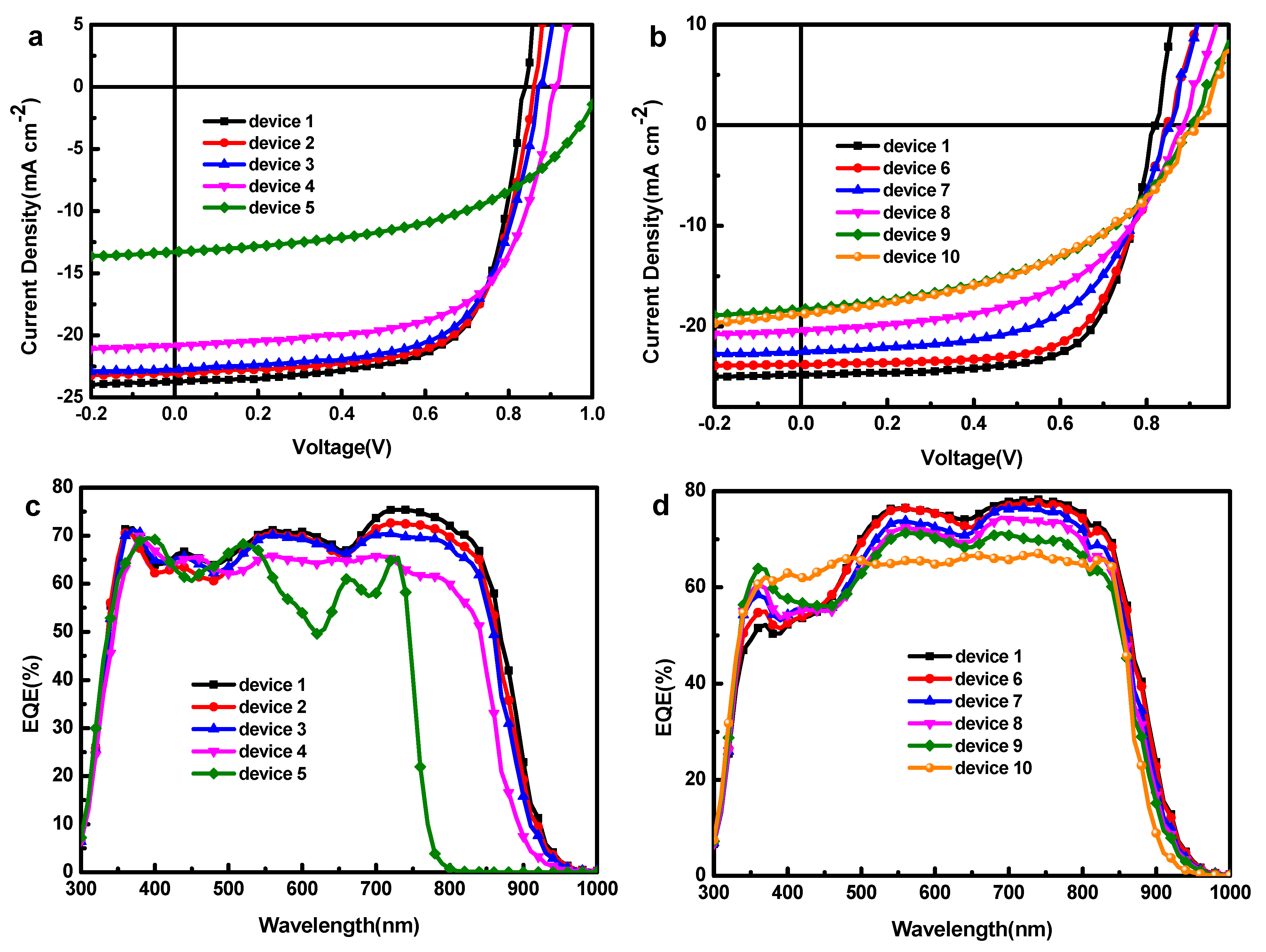
Figure 1. (a) The structure of solar cells device, (b) the energy level diagram and (c) the molecular structure of the polymer donor PM6 and the non-fullerene acceptor Y6 and ITIC-M.
Polymers 13 02398 g001
Figure 2. Absorption spectra of (a) pure PM6, Y6 and ITIC-M films normalized, respectively, at their peak, (b) blend films 1–5 normalized at 450 nm, (c) blend films 1, 6–10 normalized at 845 nm.
Polymers 13 02398 g002
Figure 3. J-V characteristics of (a) devices 1 to 5, (b) devices 1, 6 to 10, EQE curves of (c) device 1 to 5, (d) device 1, 6 to 10. (Rsh) and series (Rs) resistances of these devices are from their J-V curves.
Polymers 13 02398 g003
Figure 4. AFM topography images (above) and the corresponding phase images (below) of 5 × 5 μm2 area of (a) film 1, film 4, film 5, (b) film 8 and film 10, (c) GIXRD with out-of-plane scattering geometry for film 1, 4, 8.
Polymers 13 02398 g004
Figure 5. EL spectroscopy of (a) devices 1 to 5 (inset image is EL spectroscopy of film 1 to 4), (b) devices 1, 6 to 10, PL spectra of (c) pure PM6 film, ITIC-M film and films 1 to 5, (d) pure PM6 film and films 1, 6 to 10, excited at 550 nm. Multiple peaks, Gaussian fitting of (e) EL spectroscopy of device 4 and (f) PL spectroscopy of film 4.
Polymers 13 02398 g005
Figure 6. (a) EL spectroscopy of device 1, 5, 11 and 12 (inset image is multiple peaks Gaussian fitting of device 12), (b) charge transfer model of PM6:Y6:ITIC-M ternary solar cells.
Polymers 13 02398 g006
Figure 7. Dark J-V characteristics of hoe-only devices (a) 1 to 5, (b) 1, 6 to 10. Dark J-V characteristics of electron-only devices (c) 1 to 5, (d) 1, 6 to 10, (e) photocurrent density (Jph) versus effective voltage (Veff) for devices 1, 4 and 8, (f) dark J-V curves of devices 1, 4 and 8.
Polymers 13 02398 g007
Table 1. Performance parameters of devices 1 to 5.
DeviceVoc (V)Jsc (mA cm−2)FF (%)PCE (%)Rs (Ω cm2)Rsh (Ω cm2)
10.8324.8068.3014.034.62964.16
20.8622.9967.3413.345.01812.24
30.8822.6865.2112.965.73724.28
40.9120.7864.1312.166.18644.32
51.0213.2751.266.9615.95571.16
Table 2. Performance parameters of devices 1, 6 to 10.
DeviceVoc (V)Jsc (mA cm−2)FF (%)PCE (%)Rs (Ω cm2)Rsh (Ω cm2)
10.8324.8068.3014.034.62964.16
60.8523.7665.8613.276.911332.92
70.8622.4858.7911.408.25619.36
80.8920.3653.889.778.54421.92
90.9118.3247.397.9313.04330.72
100.9118.7445.627.7913.21217.64
Table 3. Summary of charge carrier mobility calculated by SCLC.
Devicesμh (cm2 V−1 s−1)μe (cm2 V−1 s−1)μh/μe
19.62 × 10−48.98 × 10−41.07
24.50 × 10−42.01 × 10−42.38
33.57 × 10−41.82 × 10−41.96
41.27 × 10−41.08 × 10−41.17
58.38 × 10−61.42 × 10−50.59
69.56 × 10−44.10 × 10−42.33
79.35 × 10−43.71 × 10−42.52
89.18 × 10−43.17 × 10−42.89
97.21 × 10−42.80 × 10−42.58
103.76 × 10−49.67 × 10−53.88
Publisher’s Note: MDPI stays neutral with regard to jurisdictional claims in published maps and institutional affiliations.

