Influence of Mechanical Couplings on the Dynamical Behavior and Energy Harvesting of a Composite Structure


Abstract
:
1. Introduction
2. Composite Active Beam Modeling
3. Numerical Results
4. Conclusions
Author Contributions
Funding
Institutional Review Board Statement
Informed Consent Statement
Data Availability Statement
Acknowledgments
Conflicts of Interest
References
- Rincón-Casado, A.; González-Carbajal, J.; García-Vallejo, D.; Domínguez, J. Analytical and numerical study of the influence of different support types in the nonlinear vibrations of beams. Eur. J. Mech. A/Solids 2021, 85, 104113. [Google Scholar] [CrossRef]
- Kloda, L.; Lenci, S.; Warminski, J. Nonlinear dynamics of a planar beam–spring system: Analytical and numerical approaches. Nonlinear Dyn. 2018, 94, 1721–1738. [Google Scholar] [CrossRef] [Green Version]
- Kloda, L.; Lenci, S.; Warminski, J. Nonlinear Dynamics of a Planar Hinged-Supported Beam with One End Lumped Mass and Longitudinal Elastic Support. MATEC Web Conf. 2018, 241, 01016. [Google Scholar] [CrossRef] [Green Version]
- Kloda, L.; Lenci, S.; Warminski, J. Nonlinear Dynamics of a Planar Hinged-Simply Supported Beam with One End Spring: Higher Order Resonances. IUTAM Symp. Exploit. Nonlinear Dyn. Eng. Syst. 2019, 37, 155–165. [Google Scholar] [CrossRef]
- Kloda, L.; Lenci, S.; Warminski, J. Hardening vs. softening dichotomy of a hinged-simply supported beam with one end axial linear spring: Experimental and numerical studies. Int. J. Mech. Sci. 2020, 178, 105588. [Google Scholar] [CrossRef]
- Lenci, S.; Clementi, F.; Kloda, L.; Warminski, J.; Rega, G. Longitudinal–transversal internal resonances in Timoshenko beams with an axial elastic boundary condition. Nonlinear Dyn. 2020. [Google Scholar] [CrossRef]
- Warminski, J.; Kloda, L.; Lenci, S. Nonlinear vibrations of an extensional beam with tip mass in slewing motion. Meccanica 2020, 55, 2311–2335. [Google Scholar] [CrossRef]
- Swanson, S.R. Introduction to Design and Analysis with Advanced Composite Materials; Prentice Hall: Englewood Cliffs, NJ, USA, 1997. [Google Scholar]
- Latalski, J. A coupled-field model of a rotating composite beam with an integrated nonlinear piezoelectric active element. Nonlinear Dyn. 2017, 90, 2145–2162. [Google Scholar] [CrossRef] [Green Version]
- Kollar, L.P.; Springer, G.S. Mechanics of Composite Structures; Cambridge University Press: Cambridge, UK; New York, NY, USA, 2003. [Google Scholar]
- Santiuste, C.; Sánchez-Sáez, S.; Barbero, E. Dynamic analysis of bending–torsion coupled composite beams using the Flexibility Influence Function Method. Int. J. Mech. Sci. 2008, 50, 1611–1618. [Google Scholar] [CrossRef] [Green Version]
- Gawryluk, J.; Bocheński, M.; Teter, A. Modal analysis of laminated “CAS” and “CUS” box-beams. Arch. Mech. Eng. 2017, 64, 441–454. [Google Scholar] [CrossRef] [Green Version]
- Latalski, J.; Bochenski, M.; Warminski, J. Control of Bending-Bending Coupled Vibrations of a Rotating Thin-Walled Composite Beam. Arch. Acoust. 2014, 39, 605–613. [Google Scholar] [CrossRef] [Green Version]
- Latalski, J.; Warminski, J.; Rega, G. Bending-twisting vibrations of a rotating hub-thin-walled composite beam system. Math. Mech. Solids 2017, 22, 1303–1325. [Google Scholar] [CrossRef]
- Czapski, P.; Kubiak, T. Influence of Fibre Arrangement on the Buckling Load of Composite Plates—Analytical Solution. Fibres Text. East. Eur. 2015, 23, 92–97. [Google Scholar] [CrossRef]
- Cui, D.; Li, D. Bending-twisting coupled structures based on composite laminates with extension-shear coupling effect. Compos. Struct. 2019, 209, 434–442. [Google Scholar] [CrossRef]
- Murray, R.E.; Doman, D.A.; Pegg, M.J. Finite element modeling and effects of material uncertainties in a composite laminate with bend–twist coupling. Compos. Struct. 2015, 121, 362–376. [Google Scholar] [CrossRef]
- Teter, A.; Gawryluk, J.; Bochenski, M. Experimental and numerical studies of a cracked thin-walled box-beams. Compos. Struct. 2018, 202, 807–817. [Google Scholar] [CrossRef]
- Falkowicz, K.; Debski, H.; Wysmulski, P. Effect of extension-twisting and extension-bending coupling on a compressed plate with a cut-out. Compos. Struct. 2020, 238, 111941. [Google Scholar] [CrossRef]
- Anton, S.; Sodano, H. A Review of Power Harvesting Using Piezoelectric Materials (2003–2006). Smart Mater. Struct. 2007, 16, R1. [Google Scholar] [CrossRef]
- Safaei, M.; Sodano, H.A.; Anton, S.R. A review of energy harvesting using piezoelectric materials: State-of-the-art a decade later (2008–2018). Smart Mater. Struct. 2019, 28, 113001. [Google Scholar] [CrossRef]
- Sodano, H.; Inman, D. A Review of Power Harvesting From Vibration Using Piezoelectric Materials. Shock Vib. Dig. 2004, 36, 197–205. [Google Scholar] [CrossRef] [Green Version]
- Li, X.; Upadrashta, D.; Yu, K.; Yang, Y. Sandwich piezoelectric energy harvester: Analytical modeling and experimental validation. Energy Convers. Manag. 2018, 176, 69–85. [Google Scholar] [CrossRef]
- Latalski, J.; Kowalczuk, M. Experimental vs. analytical modal analysis of a composite circumferentially asymmetric stiffness box beam. AIP Conf. Proc. 2017, 100018. [Google Scholar] [CrossRef]
- Krzyzak, A.; Kosicka, E.; Borowiec, M.; Szczepaniak, R. Selected Tribological Properties and Vibrations in the Base Resonance Zone of the Polymer Composite Used in the Aviation Industry. Materials 2020, 13, 1364. [Google Scholar] [CrossRef] [PubMed] [Green Version]
- Borowiec, M.; Bochenski, M.; Gawryluk, J.; Augustyniak, M. Analysis of the Macro Fiber Composite Characteristics for Energy Harvesting Efficiency. In Dynamical Systems: Theoretical and Experimental Analysis; Springer: Cham, Switzerland, 2016; Volume 182. [Google Scholar] [CrossRef]
- Yang, Y.; Tang, L.; Li, H. Vibration energy harvesting using macro-fiber composites. Smart Mater. Struct. 2009, 18, 115025. [Google Scholar] [CrossRef]
- Gawryluk, J.; Mitura, A.; Teter, A. Dynamic control of kinematically excited laminated, thin-walled beam using macro fibre composite actuator. Compos. Struct. 2020, 236, 111898. [Google Scholar] [CrossRef]
- Available online: https://www.smart-material.com/MFC-product-P1.html (accessed on 21 November 2020).
- Borowiec, M.; Bocheński, M. Energy harvesting of a composite beam with optimizing stacking sequence of layers. AIP Conf. Proc. 2020, 2239, 020003. [Google Scholar] [CrossRef]
- Jarzyna, W.; Augustyniak, M.; Warminski, J.; Bochenski, M. Characteristics and implementation of the piezoelectric structures in active composite systems. Prz. Elektrotechniczny 2010, 86, 320–322. [Google Scholar]


| Dimensions | Beam | Piezo Type M8514-P1 |
|---|---|---|
| length | 300 mm | 85 mm |
| width | 20 mm | 14 mm |
| thickness | 2.75 mm | 0.3 mm |
| Composite Layer | |
| longitudinal modulus | 46.4 GPa |
| transverse modulus | 14.9 GPa |
| shear modulus | 5.20 GPa |
| Poisson’s ratio | 0.27 |
| mass density | 2032 kg/m3 |
| Active Element | |
| Young’s modulus | 6.75 GPa |
| Poisson’s ratio | 0.31 |
| piezoelectric constant | 1.02 × m/V |
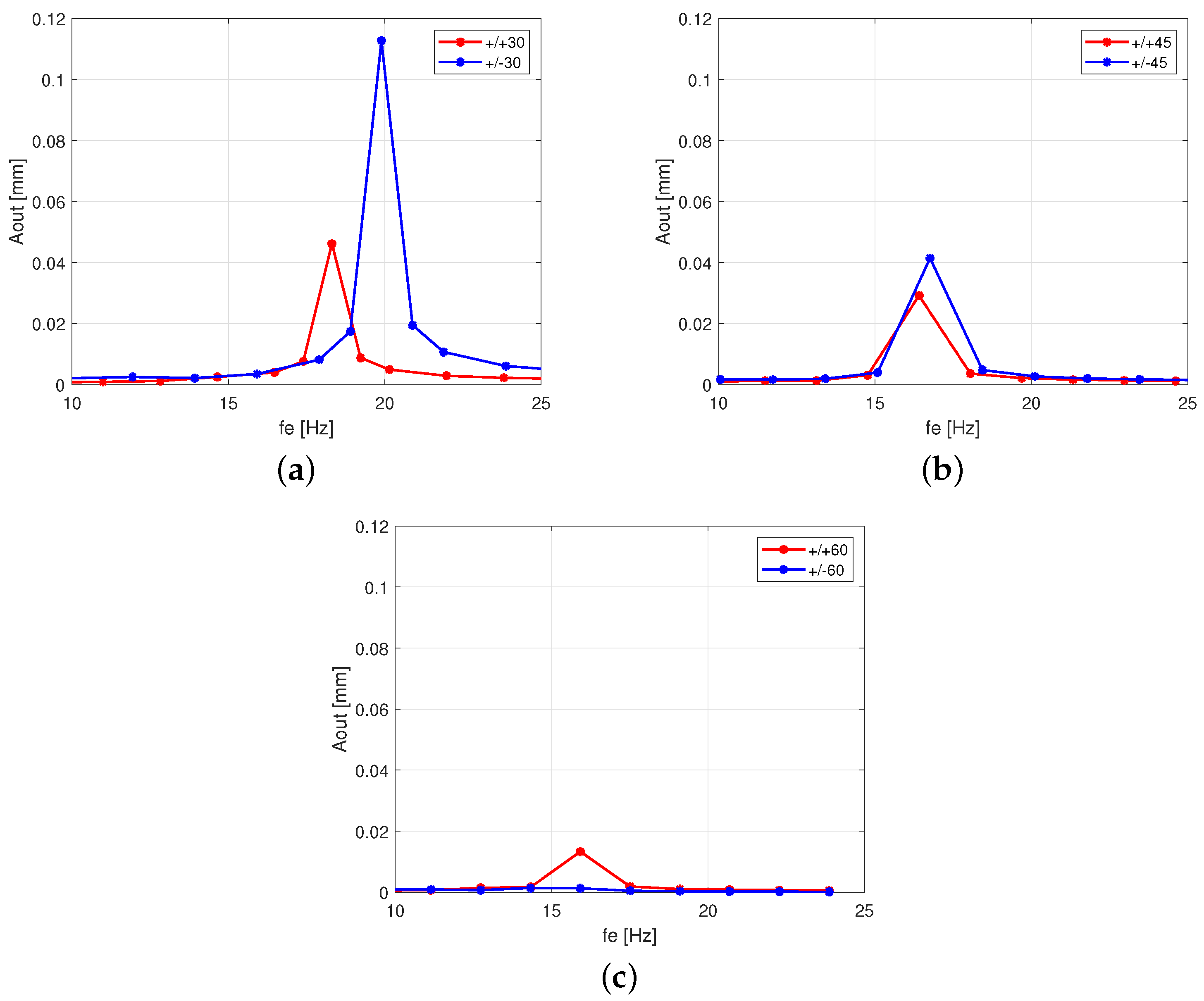
| Stacking Sequence | (Hz) |
|---|---|
| +30 (5)/0/−30 (5) | 19.89 |
| +30 (5)/0/+30 (5) | 18.31 |
| +45 (5)/0/−45 (5) | 16.76 |
| +45 (5)/0/+45 (5) | 16.41 |
| +60 (5)/0/−60 (5) | 15.92 |
| +60 (5)/0/+60 (5) | 15.91 |
Publisher’s Note: MDPI stays neutral with regard to jurisdictional claims in published maps and institutional affiliations. |
© 2020 by the authors. Licensee MDPI, Basel, Switzerland. This article is an open access article distributed under the terms and conditions of the Creative Commons Attribution (CC BY) license (http://creativecommons.org/licenses/by/4.0/).
Share and Cite
Borowiec, M.; Gawryluk, J.; Bochenski, M. Influence of Mechanical Couplings on the Dynamical Behavior and Energy Harvesting of a Composite Structure. Polymers 2021, 13, 66. https://doi.org/10.3390/polym13010066
Borowiec M, Gawryluk J, Bochenski M. Influence of Mechanical Couplings on the Dynamical Behavior and Energy Harvesting of a Composite Structure. Polymers. 2021; 13(1):66. https://doi.org/10.3390/polym13010066
Chicago/Turabian StyleBorowiec, Marek, Jaroslaw Gawryluk, and Marcin Bochenski. 2021. "Influence of Mechanical Couplings on the Dynamical Behavior and Energy Harvesting of a Composite Structure" Polymers 13, no. 1: 66. https://doi.org/10.3390/polym13010066