Microfluidic Technology for the Production of Well-Ordered Porous Polymer Scaffolds

Abstract
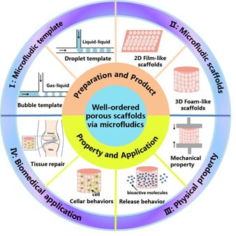
:
1. Introduction
2. Well-Ordered Porous Scaffolds
3. Well-Ordered Porous Scaffolds Based on Microfluidic Technology
3.1. Bubble Template
3.2. Droplet Template
4. Microfluidic Scaffolds and Biomedical Applications
4.1. 2D Film-Like Scaffolds
4.2. 3D Foam-Like Scaffolds
5. Conclusions
Author Contributions
Funding
Conflicts of Interest
References
- Ambekar, R.S.; Kandasubramanian, B. Progress in the advancement of porous biopolymer scaffold: Tissue engineering application. Ind. Eng. Chem. Res. 2019, 58, 6163–6194. [Google Scholar] [CrossRef]
- Tiwari, S.; Patil, R.; Bahadur, P. Polysaccharide based scaffolds for soft tissue engineering applications. Polymers 2018, 11, 1. [Google Scholar] [CrossRef] [Green Version]
- Bose, S.; Roy, M.; Bandyopadhyay, A. Recent advances in bone tissue engineering scaffolds. Trends Biotechnol. 2012, 30, 546–554. [Google Scholar] [CrossRef]
- Baino, F.; Fiorilli, S.; Vitale-Brovarone, C. Bioactive glass-based materials with hierarchical porosity for medical applications: Review of recent advances. Acta Biomater. 2016, 42, 18–32. [Google Scholar] [CrossRef]
- Loh, Q.L.; Choong, C. Three-dimensional scaffolds for tissue engineering applications: Role of porosity and pore size. Tissue Eng. Part B: Rev. 2013, 19, 485–502. [Google Scholar] [CrossRef] [Green Version]
- Hollister, S.J. Porous scaffold design for tissue engineering. Nat. Mater. 2005, 4, 518–524. [Google Scholar] [CrossRef]
- Zhang, W.; Wang, Z.; Xie, C.; Wang, X.; Luo, F.; Hong, M.; Zhou, R.; Ma, C.; Lin, N.; Zhang, J.; et al. Scaffold with micro/macro-architecture for myocardial alignment engineering into complex 3d cell patterns. Adv. Healthc. Mater. 2019, 8, 1–7. [Google Scholar] [CrossRef]
- Udomluck, N.; Koh, W.-G.; Lim, D.-J.; Park, H. Recent developments in nanofiber fabrication and modification for bone tissue engineering. Int. J. Mol. Sci. 2020, 21, 99. [Google Scholar] [CrossRef] [Green Version]
- Barralet, J.E.; Wang, L.; Lawson, M.; Triffitt, J.T.; Cooper, P.R.; Shelton, R.M. Comparison of bone marrow cell growth on 2d and 3d alginate hydrogels. J. Mater. Sci.Mater. Med. 2005, 16, 515–519. [Google Scholar] [CrossRef] [Green Version]
- Yamamoto, S.; Tanaka, M.; Sunami, H.; Ito, E.; Yamashita, S.; Morita, Y.; Shimomura, M. Effect of honeycomb-patterned surface topography on the adhesion and signal transduction of porcine aortic endothelial cells. Langmuir 2007, 23, 8114–8120. [Google Scholar] [CrossRef]
- Hahn, M.S.; Miller, J.S.; West, J.L. Three-dimensional biochemical and biomechanical patterning ofhydrogels for guiding cell behavior. Adv. Mater. 2006, 18, 2679–2684. [Google Scholar] [CrossRef]
- Dai, W.; Kawazoe, N.; Lin, X.; Dong, J.; Chen, G. The influence of structural design of plga/collagen hybrid scaffolds in cartilage tissue engineering. Biomaterials 2010, 31, 2141–2152. [Google Scholar] [CrossRef] [PubMed]
- Fereshteh, Z.; Fathi, M.; Bagri, A.; Boccaccini, A.R. Preparation and characterization of aligned porous pcl/zein scaffolds as drug delivery systems via improved unidirectional freeze-drying method. Mater. Sci. Eng. CMater. Biol. Appl. 2016, 68, 613–622. [Google Scholar] [CrossRef] [PubMed]
- Chuaponpat, N.; Ueda, T.; Ishigami, A.; Kurose, T.; Ito, H. Morphology, thermal and mechanical properties of co-continuous porous structure of pla/pva blends by phase separation. Polymers 2020, 12, 1083. [Google Scholar] [CrossRef] [PubMed]
- Liao, X.; Zhang, H.; He, T. Preparation of porous biodegradable polymer and its nanocomposites by supercritical co2 foaming for tissue engineering. J. Nanomater. 2012, 2012, 1–12. [Google Scholar] [CrossRef] [Green Version]
- Gualandi, C.; White, L.J.; Chen, L.; Gross, R.A.; Shakesheff, K.M.; Howdle, S.M.; Scandola, M. Scaffold for tissue engineering fabricated by non-isothermal supercritical carbon dioxide foaming of a highly crystalline polyester. Acta Biomater. 2010, 6, 130–136. [Google Scholar] [CrossRef]
- Mao, J.; Duan, S.; Song, A.; Cai, Q.; Deng, X.; Yang, X. Macroporous and nanofibrous poly(lactide-co-glycolide)(50/50) scaffolds via phase separation combined with particle-leaching. Mater. Sci. Eng. C 2012, 32, 1407–1414. [Google Scholar] [CrossRef]
- Hou, Q.; Grijpma, D.W.; Feijen, J. Porous polymeric structures for tissue engineering prepared by a coagulation, compression moulding and salt leaching technique. Biomaterials 2003, 24, 1937–1947. [Google Scholar] [CrossRef]
- Zhao, P.; Li, D.; Yang, F.; Ma, Y.; Wang, T.; Duan, S.; Shen, H.; Cai, Q.; Wu, D.; Yang, X.; et al. In vitro and in vivo drug release behavior and osteogenic potential of a composite scaffold based on poly(ε-caprolactone)-block-poly(lactic-co-glycolic acid) and β-tricalcium phosphate. J. Mater. Chem. B 2015, 3, 6885–6896. [Google Scholar] [CrossRef]
- Wu, D.; Xu, F.; Sun, B.; Fu, R.; He, H.; Matyjaszewski, K. Design and preparation of porous polymers. Chem. Rev. 2012, 112, 3959–4015. [Google Scholar] [CrossRef]
- Aldemir Dikici, B.; Reilly, G.C.; Claeyssens, F. Boosting the osteogenic and angiogenic performance of multiscale porous polycaprolactone scaffolds by in vitro generated extracellular matrix decoration. Acs Appl. Mater. Interfaces 2020, 12, 12510–12524. [Google Scholar] [CrossRef] [PubMed] [Green Version]
- Chen, J.; Zhang, T.; Hua, W.; Li, P.; Wang, X. 3d porous poly(lactic acid) regenerated cellulose composite scaffolds based on electrospun nanofibers for biomineralization. Colloids Surf. A Physicochem. Eng. Asp. 2020, 585, 124048–124061. [Google Scholar] [CrossRef]
- Sun, B.; Jiang, X.-J.; Zhang, S.; Zhang, J.-C.; Li, Y.-F.; You, Q.-Z.; Long, Y.-Z. Electrospun anisotropic architectures and porous structures for tissue engineering. J. Mater. Chem. B 2015, 3, 5389–5410. [Google Scholar] [CrossRef] [PubMed]
- Han, D.G.; Ahn, C.B.; Lee, J.-H.; Hwang, Y.; Kim, J.H.; Park, K.Y.; Lee, J.W.; Son, K.H. Optimization of electrospun poly(caprolactone) fiber diameter for vascular scaffolds to maximize smooth muscle cell infiltration and phenotype modulation. Polymers 2019, 11, 643. [Google Scholar] [CrossRef] [PubMed] [Green Version]
- Yao, B.; Zhu, Q.; Yao, L.; Hao, J. Fabrication of honeycomb-structured poly(ethylene glycol)-block-poly(lactic acid) porous films and biomedical applications for cell growth. Appl. Surf. Sci. 2015, 332, 287–294. [Google Scholar] [CrossRef]
- Daly, R.; Sader, J.E.; Boland, J.J. Taming self-organization dynamics to dramatically control porous architectures. Acs Nano 2016, 10, 3087–3092. [Google Scholar] [CrossRef]
- Elsayed, M.; Kothandaraman, A.; Edirisinghe, M.; Huang, J. Porous polymeric films from microbubbles generated using a t-junction microfluidic device. Langmuir 2016, 32, 13377–13385. [Google Scholar] [CrossRef]
- Gultekinoglu, M.; Jiang, X.; Bayram, C.; Ulubayram, K.; Edirisinghe, M. Honeycomb-like plga- b-peg structure creation with t-junction microdroplets. Langmuir 2018, 34, 7989–7997. [Google Scholar] [CrossRef]
- Zhu, P.; Kong, T.; Tang, X.; Wang, L. Well-defined porous membranes for robust omniphobic surfaces via microfluidic emulsion templating. Nat. Commun. 2017, 8, 1–10. [Google Scholar] [CrossRef] [Green Version]
- Zhu, P.; Kong, T.; Zhou, C.; Lei, L.; Wang, L. Engineering microstructure with evaporation-induced self-assembly of microdroplets. Small Methods 2018, 2, 1–10. [Google Scholar] [CrossRef]
- Zhang, Y.S.; Zhu, C.; Xia, Y. Inverse opal scaffolds and their biomedical applications. Adv. Mater. 2017, 29, 1–25. [Google Scholar] [CrossRef]
- Choi, S.-W.; Zhang, Y.; Xia, Y. Three-dimensional scaffolds for tissue engineering: The importance of uniformity in pore size and structure. Langmuir 2010, 26, 19001–19006. [Google Scholar] [CrossRef] [Green Version]
- Luo, Y.; Lode, A.; Sonntag, F.; Nies, B.; Gelinsky, M. Well-ordered biphasic calcium phosphate-alginate scaffolds fabricated by multi-channel 3d plotting under mild conditions. J. Mater. Chem. B 2013, 1, 4088–4098. [Google Scholar] [CrossRef] [PubMed]
- Dorj, B.; Won, J.E.; Purevdorj, O.; Patel, K.D.; Kim, J.H.; Lee, E.J.; Kim, H.W. A novel therapeutic design of microporous-structured biopolymer scaffolds for drug loading and delivery. Acta Biomater. 2014, 10, 1238–1250. [Google Scholar] [CrossRef] [PubMed]
- Nouri-Goushki, M.; Mirzaali, M.J.; Angeloni, L.; Fan, D.; Minneboo, M.; Ghatkesar, M.K.; Staufer, U.; Fratila-Apachitei, L.E.; Zadpoor, A.A. 3d printing of large areas of highly ordered submicron patterns for modulating cell behavior. Acs Appl. Mater. Interfaces 2019, 12, 200–208. [Google Scholar] [CrossRef] [PubMed] [Green Version]
- Esposito Corcione, C.; Gervaso, F.; Scalera, F.; Padmanabhan, S.K.; Madaghiele, M.; Montagna, F.; Sannino, A.; Licciulli, A.; Maffezzoli, A. Highly loaded hydroxyapatite microsphere/ pla porous scaffolds obtained by fused deposition modelling. Ceram. Int. 2019, 45, 2803–2810. [Google Scholar] [CrossRef]
- Athukoralalage, S.S.; Balu, R.; Dutta, N.K.; Roy Choudhury, N. 3d bioprinted nanocellulose-based hydrogels for tissue engineering applications: A brief review. Polymers 2019, 11, 898. [Google Scholar] [CrossRef] [Green Version]
- Zhao, X.; Bian, F.; Sun, L.; Cai, L.; Li, L.; Zhao, Y. Microfluidic generation of nanomaterials for biomedical applications. Small 2019, 16, 1901943–1901962. [Google Scholar] [CrossRef]
- Araujo, F.; Shrestha, N.; Shahbazi, M.-A.; Liu, D.F.; Barbara, H.B.; Makila, E.M.; Salonen, J.J.; Jouni, T.H.; Granja, P.L.; Sarmento, B.; et al. Microfluidic assembly of a multifunctional tailorablecomposite system designed for site specific combined oral delivery of peptide drugs. Acs Nano 2015, 9, 8291–8302. [Google Scholar] [CrossRef]
- Zhu, P.; Wang, L. Passive and active droplet generation with microfluidics: A review. Lab Chip 2016, 17, 34–75. [Google Scholar] [CrossRef]
- Shang, L.; Cheng, Y.; Zhao, Y. Emerging droplet microfluidics. Chem. Rev. 2017, 117, 7964–8040. [Google Scholar] [CrossRef] [PubMed]
- Zhang, T.; Hong, Z.-Y.; Tang, S.-Y.; Li, W.; Inglis, D.W.; Hosokawa, Y.; Yalikun, Y.; Li, M. Focusing of sub-micrometer particles in microfluidic devices. Lab A Chip 2020, 20, 35–53. [Google Scholar] [CrossRef] [PubMed]
- Wang, B.; Prinsen, P.; Wang, H.; Bai, Z.; Wang, H.; Luque, R.; Xuan, J. Macroporous materials: Microfluidic fabrication, functionalization and applications. Chem. Soc. Rev. 2017, 46, 855–914. [Google Scholar] [CrossRef] [Green Version]
- Chung, B.G.; Lee, K.-H.; Khademhosseini, A.; Lee, S.-H. Microfluidic fabrication of microengineered hydrogels and their application in tissue engineering. Lab A Chip 2012, 12, 45–59. [Google Scholar] [CrossRef]
- Martynov, S.; Wang, X.; Stride, E.P.; Edirisinghe, M.J. Preparation of a micro-porous alginate gel using a microfluidic bubbling device. Int. J. Food Eng. 2010, 6, 1–12. [Google Scholar] [CrossRef]
- Haider, A.; Haider, S.; Rao Kummara, M.; Kamal, T.; Alghyamah, A.-A.A.; Jan Iftikhar, F.; Bano, B.; Khan, N.; Amjid Afridi, M.; Soo Han, S.; et al. Advances in the scaffolds fabrication techniques using biocompatible polymers and their biomedical application: A technical and statistical review. J. Saudi Chem. Soc. 2020, 24, 186–215. [Google Scholar] [CrossRef]
- Wu, X.; Liu, Y.; Li, X.; Wen, P.; Zhang, Y.; Long, Y.; Wang, X.; Guo, Y.; Xing, F.; Gao, J. Preparation of aligned porous gelatin scaffolds by unidirectional freeze-drying method. Acta Biomater. 2010, 6, 1167–1177. [Google Scholar] [CrossRef]
- Li, J.; Cheng, J.; Zhang, Y.; Gopalakrishnakone, P. Influence of vacuum on the formation of porous polymer films via water droplets templating. Colloid Polym. Sci. 2008, 287, 29–36. [Google Scholar] [CrossRef]
- Andrieux, S.; Drenckhan, W.; Stubenrauch, C. Generation of solid foams with controlled polydispersity using microfluidics. Langmuir 2018, 34, 1581–1590. [Google Scholar] [CrossRef]
- Amoyav, B.; Benny, O. Microfluidic based fabrication and characterization of highly porous polymeric microspheres. Polymers 2019, 11, 419. [Google Scholar] [CrossRef] [Green Version]
- Cai, Y.; Wu, F.; Yu, Y.; Liu, Y.; Shao, C.; Gu, H.; Li, M.; Zhao, Y. Porous scaffolds from droplet microfluidics for prevention of intrauterine adhesion. Acta Biomater. 2019, 84, 222–230. [Google Scholar] [CrossRef]
- Utada, A.S.; Lorenceau, E.; Link, D.R.; Kaplan, P.D.; Stone, H.A.; Weitz, D.A. Monodisperse double emulsions. Science 2005, 308, 537–541. [Google Scholar] [CrossRef] [Green Version]
- Teh, S.-Y.; Lin, R.; Hung, L.-H.; Lee, A.P. Droplet microfluidics. Lab A Chip 2008, 8, 198–221. [Google Scholar] [CrossRef]
- Chung, K.-Y.; Mishra, N.C.; Wang, C.-C.; Lin, F.-H.; Lin, K.-H. Fabricating scaffolds by microfluidics. Biomicrofluidics 2009, 3, 1–8. [Google Scholar] [CrossRef] [Green Version]
- Chaurasia, A.S.; Sajjadi, S. Transformable bubble-filled alginate microfibers via vertical microfluidics. Lab A Chip 2019, 19, 851–863. [Google Scholar] [CrossRef] [Green Version]
- Andrieux, S.; Drenckhan, W.; Stubenrauch, C. Highly ordered biobased scaffolds: From liquid to solid foams. Polymer 2017, 126, 425–431. [Google Scholar] [CrossRef]
- Mooney, D.J.; Baldwin, D.F.; Suh, N.P.; Vacanti, J.P.; Langer, R. Vacantis and Robert Larger. Novel approach to fabricate porous sponges ofpoly(d,l-lactic-co-glycolic acid). Biomaterials 1996, 17, 1417–1422. [Google Scholar] [CrossRef]
- Vignes-Adlera, M.; Weaire, D. New foams fresh challenges and opportunities. Curr. Opin. Colloid Interface Sci. 2008, 13, 141–149. [Google Scholar] [CrossRef]
- Maimouni, I.; Cejas, C.M.; Cossy, J.; Tabeling, P.; Russo, M. Microfluidics mediated production of foams for biomedical applications. Micromachines 2020, 11, 83. [Google Scholar] [CrossRef] [Green Version]
- Net, A.v.d.; Gryson, A.; Ranft, M.; Elias, F.; Stubenrauch, C.; Drenckhan, W. Highly structured porous solids from liquid foam templates. Colloids Surf. A Physicochem. Eng. Asp. 2009, 346, 5–10. [Google Scholar]
- Quell, A.; de Bergolis, B.; Drenckhan, W.; Stubenrauch, C. How the locus of initiation influences the morphology and the pore connectivity of a monodisperse polymer foam. Macromolecules 2016, 49, 5059–5067. [Google Scholar] [CrossRef]
- Dabrowski, M.L.; Jenkins, D.; Cosgriff-Hernandez, E.; Stubenrauch, C. Methacrylate-based polymer foams with controllable connectivity, pore shape, pore size and polydispersity. Phys. Chem. Chem. Phys. 2019, 22, 155–168. [Google Scholar] [CrossRef]
- Colosi, C.; Costantini, M.; Barbetta, A.; Pecci, R.; Bedini, R.; Dentini, M. Morphological comparison of pva scaffolds obtained by gas foaming and microfluidic foaming techniques. Langmuir 2012, 29, 82–91. [Google Scholar] [CrossRef] [PubMed]
- Wang, C.-C.; Yang, K.-C.; Lin, K.-H.; Wu, C.-C.; Liu, Y.-L.; Lin, F.-H.; Chen, I.-H. A biomimetic honeycomb-like scaffold prepared by flow-focusing technology for cartilage regeneration. Biotechnogy Bioengneering 2014, 111, 2338–2348. [Google Scholar] [CrossRef]
- Carballido, L.; Dabrowski, M.L.; Dehli, F.; Koch, L.; Stubenrauch, C. Monodisperse liquid foams via membrane foaming. J. Colloid Interface Sci. 2020, 568, 46–53. [Google Scholar] [CrossRef] [PubMed]
- Costantini, M.; Colosi, C.; Jaroszewicz, J.; Tosato, A.; Święszkowski, W.; Dentini, M.; Garstecki, P.; Barbetta, A. Microfluidic foaming: A powerful tool for tailoring the morphological and permeability properties of sponge-like biopolymeric scaffolds. Acs Appl. Mater. Interfaces 2015, 7, 23660–23671. [Google Scholar] [CrossRef]
- Costantini, M.; Colosi, C.; Mozetic, P.; Jaroszewicz, J.; Tosato, A.; Rainer, A.; Trombetta, M.; Święszkowski, W.; Dentini, M.; Barbetta, A. Correlation between porous texture and cell seeding efficiency of gas foaming and micrfludic foaming scaffolds. Mater. Sci. Eng. C 2016, 62, 668–677. [Google Scholar] [CrossRef]
- Testouri, A.; Ranft, M.; Honorez, C.; Kaabeche, N.; Ferbitz, J.; Freidank, D.; Drenckhan, W. Generation of crystalline polyurethane foams using millifluidic lab-on-a-chip technologies. Adv. Eng. Mater. 2013, 15, 1086–1098. [Google Scholar] [CrossRef]
- Quell, A.; Elsing, J.; Drenckhan, W.; Stubenrauch, C. Monodisperse polystyrene foams via microfluidics - a novel templating route. Adv. Eng. Mater. 2015, 17, 604–609. [Google Scholar] [CrossRef]
- Stubenrauch, C.; Menner, A.; Bismarck, A.; Drenckhan, W. Emulsion and foam templating-promising routes to tailor-made porous polymers. Angew. Chem. Int. Ed. 2018, 57, 10024–10032. [Google Scholar] [CrossRef]
- Costantini, M.; Jaroszewicz, J.; Kozoń, Ł.; Szlązak, K.; Święszkowski, W.; Garstecki, P.; Stubenrauch, C.; Barbetta, A.; Guzowski, J. 3d-printing of functionally graded porous materials using on-demand reconfigurable microfluidics. Angew. Chem. Int. Ed. 2019, 58, 7620–7625. [Google Scholar] [CrossRef] [PubMed]
- Wang, C.C.; Yang, K.C.; Lin, K.H.; Liu, Y.L.; Liu, H.C.; Lin, F.H. Cartilage regeneration in scid mice using a highly organized three-dimensional alginate scaffold. Biomaterials 2012, 33, 120–127. [Google Scholar] [CrossRef] [PubMed]
- Dehli, F.; Rebers, L.; Stubenrauch, C.; Southan, A. Highly ordered gelatin methacryloyl hydrogel foams with tunable pore size. Biomacromolecules 2019, 20, 2666–2674. [Google Scholar] [CrossRef]
- Russo, M.; Amara, Z.; Fenneteau, J.; Chaumont-Olive, P.; Maimouni, I.; Tabeling, P.; Cossy, J. Stable liquid foams from a new polyfluorinatedsurfactant. Chem. Commun. 2020, 56, 5807–5810. [Google Scholar] [CrossRef]
- Zhang, L.; Zhang, Y.; Chen, P.; Du, W.; Feng, X.; Liu, B.-F. Paraffin oil based soft-template approach to fabricate reusable porous pdms sponge for effective oil/water separation. Langmuir 2019, 35, 11123–11131. [Google Scholar] [CrossRef]
- Barbetta, A.; Barigelli, E.; Dentini, M. Porous alginate hydrogels synthetic methods for tailoring the porous texture. Biomacromolecules 2009, 10, 2328–2337. [Google Scholar] [CrossRef]
- Riesco, R.; Boyer, L.; Blosse, S.; Lefebvre, P.M.; Assemat, P.; Leichle, T.; Accardo, A.; Malaquin, L. Water-in-pdms emulsion templating of highly interconnected porous architectures for 3d cell culture. Acs Appl. Mater. Interfaces 2019, 11, 28631–28640. [Google Scholar] [CrossRef]
- Barbetta, A.; Dentini, M.; Vecchis, M.S.D.; Filippini, P.; Formisano, G.; Caiazza, S. Scaffolds based on biopolymeric foams. Adv. Funct. Mater. 2005, 15, 118–124. [Google Scholar] [CrossRef]
- Tian, Y.; Zhu, P.; Tang, X.; Zhou, C.; Wang, J.; Kong, T.; Xu, M.; Wang, L. Large-scale water collection of bioinspired cavity-microfibers. Nat. Commun. 2017, 8, 1081–1089. [Google Scholar] [CrossRef] [Green Version]
- Elsing, J.; Quell, A.; Stubenrauch, C. Toward functionally graded polymer foams using microfluidics. Adv. Eng. Mater. 2017, 19, 1700195–17001100. [Google Scholar] [CrossRef]
- Quell, A.; Heitkam, S.; Drenckhan, W.; Stubenrauch, C. Creating honeycomb structures in porous polymers by osmotic transport. ChemPhysChem 2017, 18, 451–454. [Google Scholar] [CrossRef] [PubMed]
- Quell, A.; Sottmann, T.; Stubenrauch, C. Diving into the finestructure of macroporous polymer foams synthesized via emulsion templating: A phase diagram study. Langmuir 2017, 33, 537–542. [Google Scholar] [CrossRef]
- Costantini, M.; Colosi, C.; Guzowski, J.; Barbetta, A.; Jaroszewicz, J.; Święszkowski, W.; Dentini, M.; Garstecki, P. Highly ordered and tunable polyhipes by using microfluidics. J. Mater. Chem. B 2014, 2, 2290–2300. [Google Scholar] [CrossRef] [PubMed] [Green Version]
- Yao, X.; Zhu, G.; Zhu, P.; Ma, J.; Chen, W.; Liu, Z.; Kong, T. Omniphobic zif-8@hydrogel membrane by microfluidic-emulsion-templating method for wound healing. Adv. Funct. Mater. 2020, 30, 1909389–1909398. [Google Scholar] [CrossRef]
- Ansari, S.; Khorshidi, S.; Karkhaneh, A. Engineering of gradient osteochondral tissue: From nature to lab. Acta Biomater. 2019, 87, 41–54. [Google Scholar] [CrossRef] [PubMed]
- Rutte, J.M.D.; Koh, J.; Carlo, D.D. Scalable high-throughput production of modular microgels for in situ assembly of microporous tissue scaffolds. Adv. Funct. Mater. 2019, 29, 1900071–1900081. [Google Scholar] [CrossRef]
- Baroud, C.N.; Gallaire, F.; Danglaa, R. Dynamics of microfluidic droplets. Lab A Chip 2010, 10, 2032–2045. [Google Scholar] [CrossRef] [Green Version]
- Chong, Z.Z.; Tan, S.H.; Ganan-Calvo, A.M.; Tor, S.B.; Loh, N.H.; Nguyen, N.T. Active droplet generation in microfluidics. Lab Chip 2016, 16, 35–58. [Google Scholar] [CrossRef] [Green Version]
- Andrieux, S.; Quell, A.; Stubenrauch, C.; Drenckhan, W. Liquid foam templating-a route to tailor-made polymer foams. Adv. Colloid Interface Sci. 2018, 256, 276–290. [Google Scholar] [CrossRef]
- Robertsa, J.R.; Rittera, D.W.; McShane, M.J. A design full of holes functional nanofilm-coated_microdomains in alginate hydrogels. J. Mater. Chem. B 2013, 107, 3195–3201. [Google Scholar] [CrossRef]
- Sergeeva, A.; Feoktistova, N.; Prokopovic, V.; Gorin, D.; Volodkin, D. Design of porous alginate hydrogels by sacrificial caco3 templates pore formation mechanism. Adv. Mater. Interfaces 2015, 2, 1500386–1500396. [Google Scholar] [CrossRef]
- Sergeeva, A.S.; Gorin, D.A.; Volodkin, D.V. In-situ assembly of ca-alginate gels with controlled pore loading/release capability. Langmuir 2015, 31, 10813–10821. [Google Scholar] [CrossRef] [PubMed]
- Paulraj, T.; Feoktistova, N.; Velk, N.; Uhlig, K.; Duschl, C.; Volodkin, D. Microporous polymeric 3d scaffolds templated by the layer-by-layer self-assembly. Macromol. Rapid Commun. 2014, 35, 1408–1413. [Google Scholar] [CrossRef] [PubMed]
- Liu, Y.; Gu, J.; Fan, D. Fabrication of high-strength and porous hybrid scaffolds based on nano-hydroxyapatite and human-like collagen for bone tissue regeneration. Polymers 2020, 12, 61. [Google Scholar] [CrossRef] [Green Version]
- Sandri, G.; Miele, D.; Faccendini, A.; Bonferoni, M.C.; Rossi, S.; Grisoli, P.; Taglietti, A.; Ruggeri, M.; Bruni, G.; Vigani, B.; et al. Chitosan/glycosaminoglycan scaffolds: The role of silver nanoparticles to control microbial infections in wound healing. Polymers 2019, 11, 1207. [Google Scholar] [CrossRef] [Green Version]
- Shuai, C.; Yu, L.; Yang, W.; Peng, S.; Zhong, Y.; Feng, P. Phosphonic acid coupling agent modification of hap nanoparticles: Interfacial effects in plla/hap bone scaffold. Polymers 2020, 12, 199. [Google Scholar] [CrossRef] [Green Version]
- Chevalier, Y.; Bolzinger, M.-A. Emulsions stabilized with solid nanoparticles: Pickering emulsions. Colloids Surf. A Physicochem. Eng. Asp. 2013, 439, 23–34. [Google Scholar] [CrossRef]
- Liu, Q.; Duan, B.; Xu, X.; Zhang, L. Progress in rigid polysaccharide-based nanocomposites with therapeutic functions. J. Mater. Chem., B 2017, 5, 5690–5713. [Google Scholar] [CrossRef]
- Ng, R.; Zang, R.; Yang, K.K.; Liu, N.; Yang, S.-T. Three-dimensional fibrous scaffolds with microstructures and nanotextures for tissue engineering. Rsc Adv. 2012, 2, 10110–10124. [Google Scholar] [CrossRef]
- Ban, Q.; Chen, W.; Du, S.; Wang, H.; Li, J.; You, R.; Jin, Y.; Xue, Y.; Guan, Y.Q. The preparation of the ordered pores colloidal crystal scaffold and its role in promoting growth of lung cells. Colloids Surf. B Biointerfaces 2019, 173, 907–917. [Google Scholar] [CrossRef]
- Tanaka, M. Design of novel 2d and 3d biointerfaces using self-organization to control cell behavior. Biochim. Et Biophys. Acta 2011, 1810, 251–258. [Google Scholar] [CrossRef] [PubMed]
- Engelmayr, G.C.; Cheng, M.; Bettinger, C.J.; Borenstein, J.T.; Langer, R.; Freed, L.E. Accordion-like honeycombs for tissue engineering of cardiac anisotropy. Nat. Mater. 2008, 7, 1003–1010. [Google Scholar] [CrossRef] [PubMed]
- Eniwumide, J.O.; Tanaka, M.; Nagai, N.; Morita, Y.; de Bruijn, J.; Yamamoto, S.; Onodera, S.; Kondo, E.; Yasuda, K.; Shimomura, M. The morphology and functions of articular chondrocytes on a honeycomb-patterned surface. Biomed Res. Int. 2014, 2014, 710354–710364. [Google Scholar] [CrossRef] [PubMed] [Green Version]
- Wang, C.-C.; Yang, K.-C.; Lin, K.-H.; Liu, H.-C.; Lin, F.-H. A highly organized three-dimensional alginate scaffold for cartilage tissue engineering prepared by microfluidic technology. Biomaterials 2011, 32, 7118–7126. [Google Scholar] [CrossRef]
- Vedadghavami, A.; Minooei, F.; Mohammadi, M.H.; Khetani, S.; Rezaei Kolahchi, A.; Mashayekhan, S.; Sanati-Nezhad, A. Manufacturing of hydrogel biomaterials with controlled mechanical properties for tissue engineering applications. Acta Biomater. 2017, 62, 42–63. [Google Scholar] [CrossRef]
- Guo, J.; Tian, X.; Xie, D.; Rahn, K.; Gerhard, E.; Kuzma, M.L.; Zhou, D.; Dong, C.; Bai, X.; Lu, Z.; et al. Citrate-based tannin-bridged bone composites for lumbar fusion. Adv. Funct. Mater. 2020, 2002438, 1–11. [Google Scholar] [CrossRef]
- Wang, Z.; Cong, Y.; Fu, J. Stretchable and tough conductive hydrogels for flexible pressure and strain sensors. J. Mater. Chem., B 2020, 8, 3437–3459. [Google Scholar] [CrossRef]
- Tang, W.; Yuan, Y.; Lin, D.; Niu, H.; Liu, C. Kaolin-reinforced 3d mbg scaffolds with hierarchical architecture and robust mechanical strength for bone tissue engineering. J. Mater. Chem. B 2014, 2, 3782–3790. [Google Scholar] [CrossRef]
- Martins, A.M.; Pereira, R.C.; Leonor, I.B.; Azevedo, H.S.; Reis, R.L. Chitosan scaffolds incorporating lysozyme into cap coatings produced by a biomimetic route: A novel concept for tissue engineering combining a self-regulated degradation system with in situ pore formation. Acta Biomater. 2009, 5, 3328–3336. [Google Scholar] [CrossRef] [Green Version]
- Liang, X.; Duan, P.; Gao, J.; Guo, R.; Qu, Z.; Li, X.; He, Y.; Yao, H.; Ding, J. Bilayered plga/plga-hap composite scaffold for osteochondral tissue engineering and tissue regeneration. ACS Biomater. Sci. Eng. 2018, 4, 3506–3521. [Google Scholar] [CrossRef]
- Martin, V.; Bettencourt, A. Bone regeneration: Biomaterials as local delivery systems with improved osteoinductive properties. Mater. Sci. Eng. C Mater. Biol. Appl. 2018, 82, 363–371. [Google Scholar] [CrossRef] [PubMed]
- Zheng, L.; Li, D.; Wang, W.; Zhang, Q.; Zhou, X.; Liu, D.; Zhang, J.; You, Z.; Zhang, J.; He, C. Bilayered scaffold prepared from a kartogenin-loaded hydrogel and bmp-2-derived peptide-loaded porous nanofibrous scaffold for osteochondral defect repair. Acs Biomater. Sci. Eng. 2019, 5, 4564–4573. [Google Scholar] [CrossRef]
- Wang, X.; Wu, X.; Xing, H.; Zhang, G.; Shi, Q.; E, L.; Liu, N.; Yang, T.; Wang, D.; Qi, F.; et al. Porous nanohydroxyapatite/collagen scaffolds loading insulin plga particles for restoration of critical size bone defect. Acs Appl. Mater. Interfaces 2017, 9, 11380–11391. [Google Scholar] [CrossRef] [PubMed]
- Morelli, S.; Salerno, S.; Piscioneri, A.; Papenburg, B.J.; di Vito, A.; Giusi, G.; Canonaco, M.; Stamatialis, D.; Drioli, E.; de Bartolo, L. Influence of micro-patterned plla membranes on outgrowth and orientation of hippocampal neurites. Biomaterials 2010, 31, 7000–7011. [Google Scholar] [CrossRef] [PubMed]
- Scaglione, S.; Giannoni, P.; Bianchini, P.; Sandri, M.; Marotta, R.; Firpo, G.; Valbusa, U.; Tampieri, A.; Diaspro, A.; Bianco, P.; et al. Order versus disorder: In vivo bone formation within osteoconductive scaffolds. Sci. Rep. 2012, 2, 1–6. [Google Scholar] [CrossRef] [Green Version]


| Methods | Pore Structures | Advantages and Limitations | Refs. |
|---|---|---|---|
| Freeze-drying technique | The pore sizes and porosity depend on the ratio of water to polymer solution and the viscosity of emulsions. Pore size < 100 μm, porosity is low. | Advantages: the elimination of several rinsing steps. Limitations: Small and disordered pores and residual solvent is dangerous for cells. | [13,14] |
| Gas foaming | The pore sizes and porosity are dependent on the pressure of carbon dioxide gas. Pore size > 100 μm and porosity > 93%. | Advantages: the elimination of the use of harsh chemical solvents. Limitations: it is difficult to ensure pore connectivity and control of the pore sizes. | [15,16] |
| Solvent casting/ particulate leaching | The pore size and geometry are determined by size and geometry of porogen, And the porosity depends on the size of the porogen and the ratio of polymer to porogen. Pore size: 50–500 μm and porosity > 80%. | Advantages: the use of small amounts of polymer. Limitations: the interpore openings and pore shape is not controllable, and takes a long time to remove the porogen, residual porogen is hazardous for cells. | [17,18,19] |
| Emulsion template | The pore size: 100 nm–2 mm and porosities (60–97%). The size distribution is highly dispersed. | Advantages: practical and inexpensive, tailoring the properties of materials flexibly. Limitations: the surfactant is difficult to remove and has certain toxicity to cells. | [20,21] |
| Electrospinning | The microstructure: nanofibrous networks and the size range from nanometer to micrometer. | Advantages: high porosity and high surface-to-volume. Limitations: the electrospun membrane is 2D structure. | [22,23,24] |
| Methods | Pore Structures | Advantages and Limitations | Refs. |
|---|---|---|---|
| Breath figure | The pore size is largely dependent on polymer property, temperature and humidity. Pore shape is regular and pore size is uniform. Pore size: 0.2–20 μm. | Advantages: simple and cheap. Limitations: the temperature and humidity must be strictly controlled and volatile solvents should be used. And the materials are limited to amphiphilic copolymer. | [25,26] |
| Microspheres cubic close-packed | The pore structure is largely dependent on microspheres template. And the obtained scaffolds have high porosity, pore size uniformity and good connectivity. Pore size: 0.05–500 μm. | Advantages: the ideal structure of scaffold. Limitations: multi-step operation and organic solvent are needed; solvent residue may be a biological toxicity affect the adhesion of cell growth. | [31,32] |
| 3D printing | The pore sizes, pore morphology and porosity are controlled by design and process. | Advantages: the fabrication of more complex shapes and controlled internal structures. Limitations: High precision equipment is expensive and applicable materials are limited. | [33,34,35,36,37] |
© 2020 by the authors. Licensee MDPI, Basel, Switzerland. This article is an open access article distributed under the terms and conditions of the Creative Commons Attribution (CC BY) license (http://creativecommons.org/licenses/by/4.0/).
Share and Cite
Zhao, P.; Wang, J.; Li, Y.; Wang, X.; Chen, C.; Liu, G. Microfluidic Technology for the Production of Well-Ordered Porous Polymer Scaffolds. Polymers 2020, 12, 1863. https://doi.org/10.3390/polym12091863
Zhao P, Wang J, Li Y, Wang X, Chen C, Liu G. Microfluidic Technology for the Production of Well-Ordered Porous Polymer Scaffolds. Polymers. 2020; 12(9):1863. https://doi.org/10.3390/polym12091863
Chicago/Turabian StyleZhao, Pei, Jianchun Wang, Yan Li, Xueying Wang, Chengmin Chen, and Guangxia Liu. 2020. "Microfluidic Technology for the Production of Well-Ordered Porous Polymer Scaffolds" Polymers 12, no. 9: 1863. https://doi.org/10.3390/polym12091863