Direct Joule Heating as a Means to Efficiently and Homogeneously Heat Thermoplastic Prepregs


Abstract
:1. Introduction
2. Fiber Reinforced Thermoplastics (FRP) and Their Processing
2.1. Heating of FRTP
2.2. Joule Heating
2.3. Aim
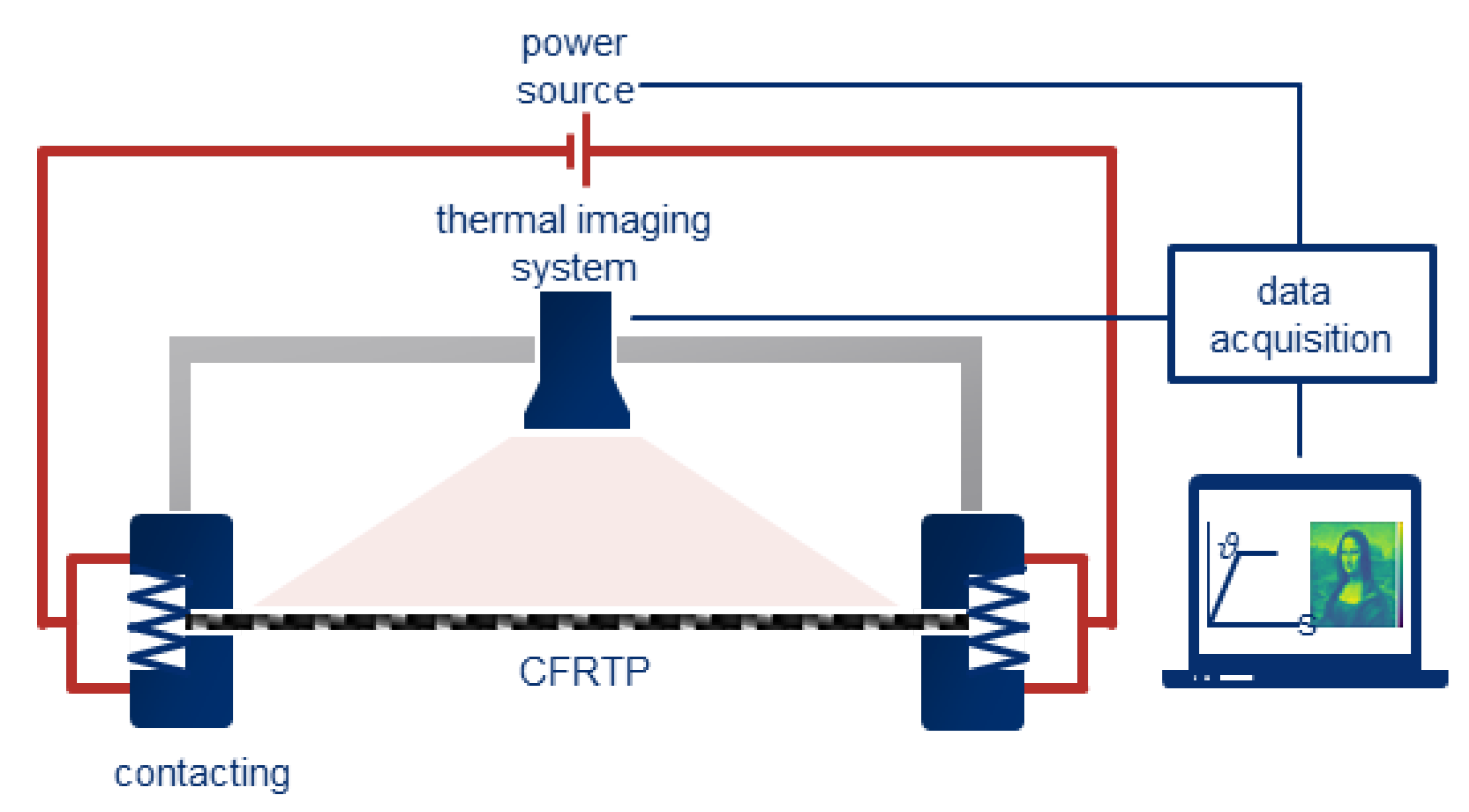
3. Experimental Setup
3.1. Test Series
3.1.1. Influence of the Contacting on the Heating Behavior
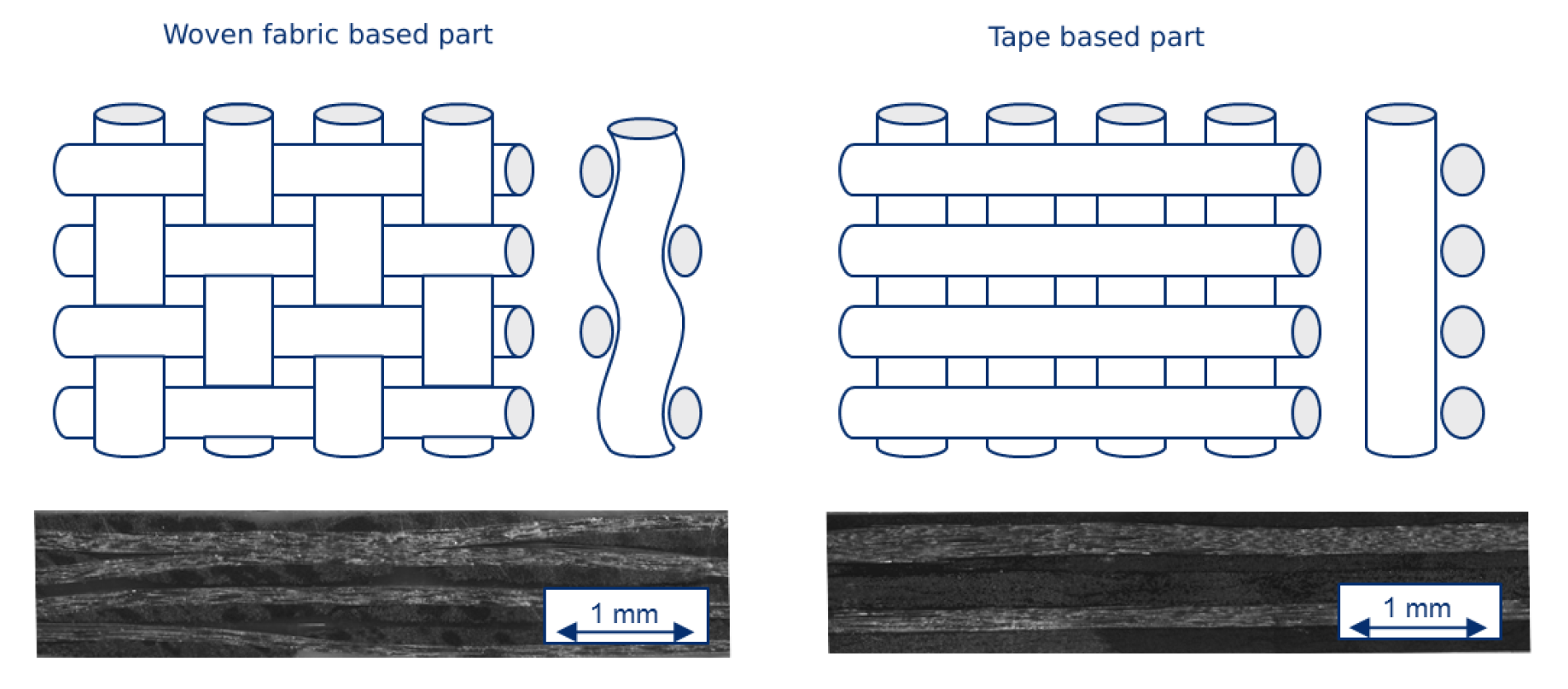
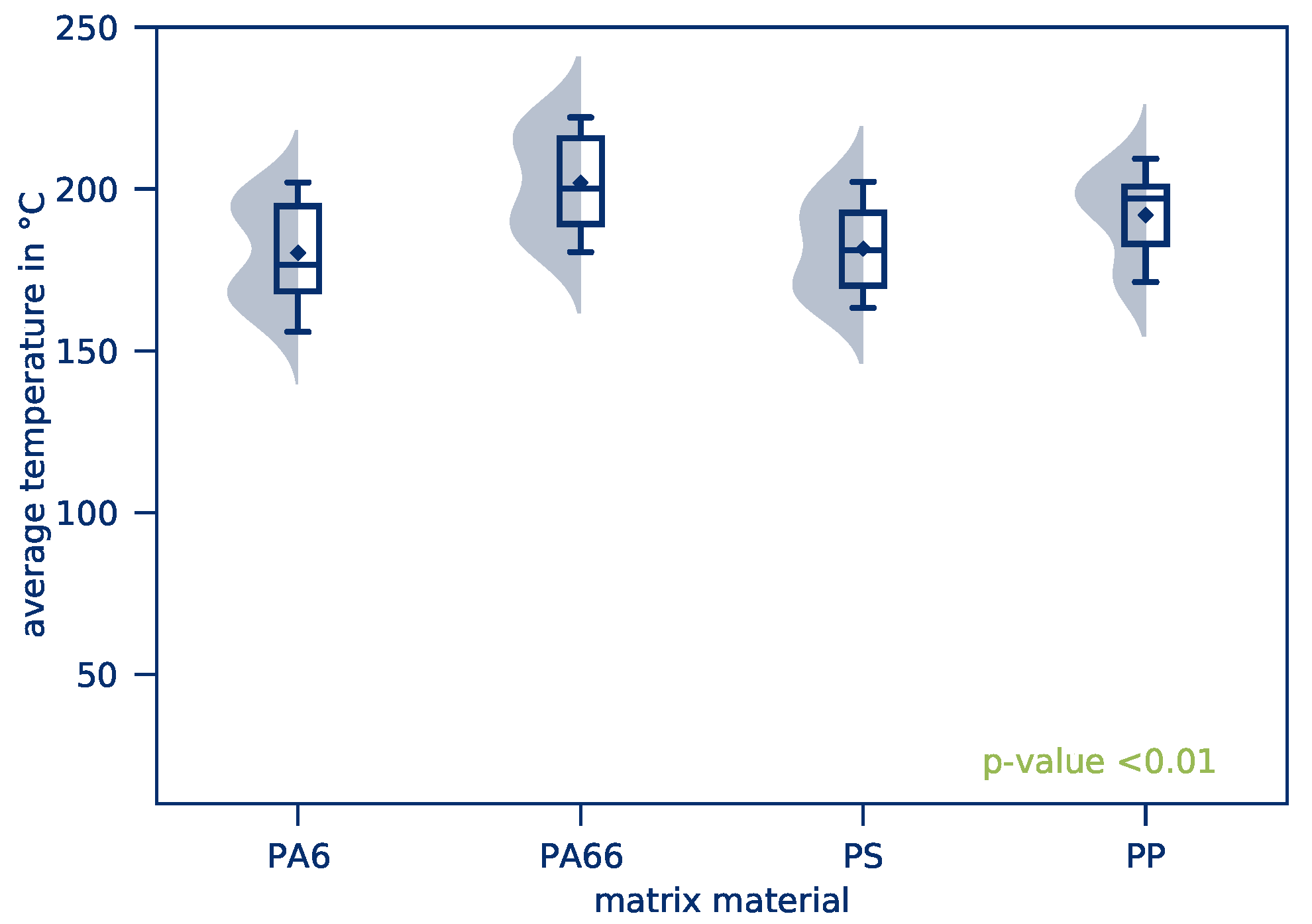
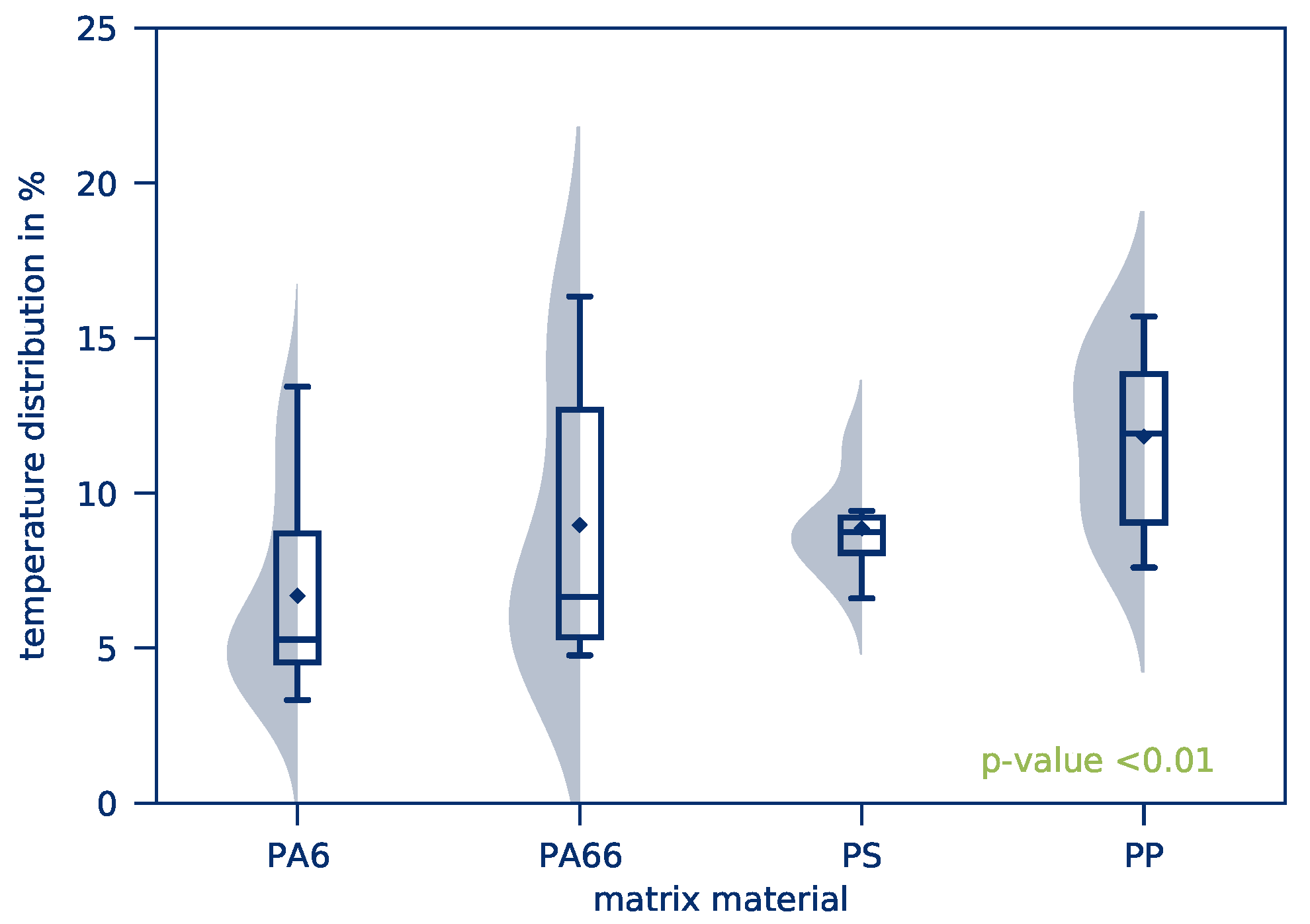
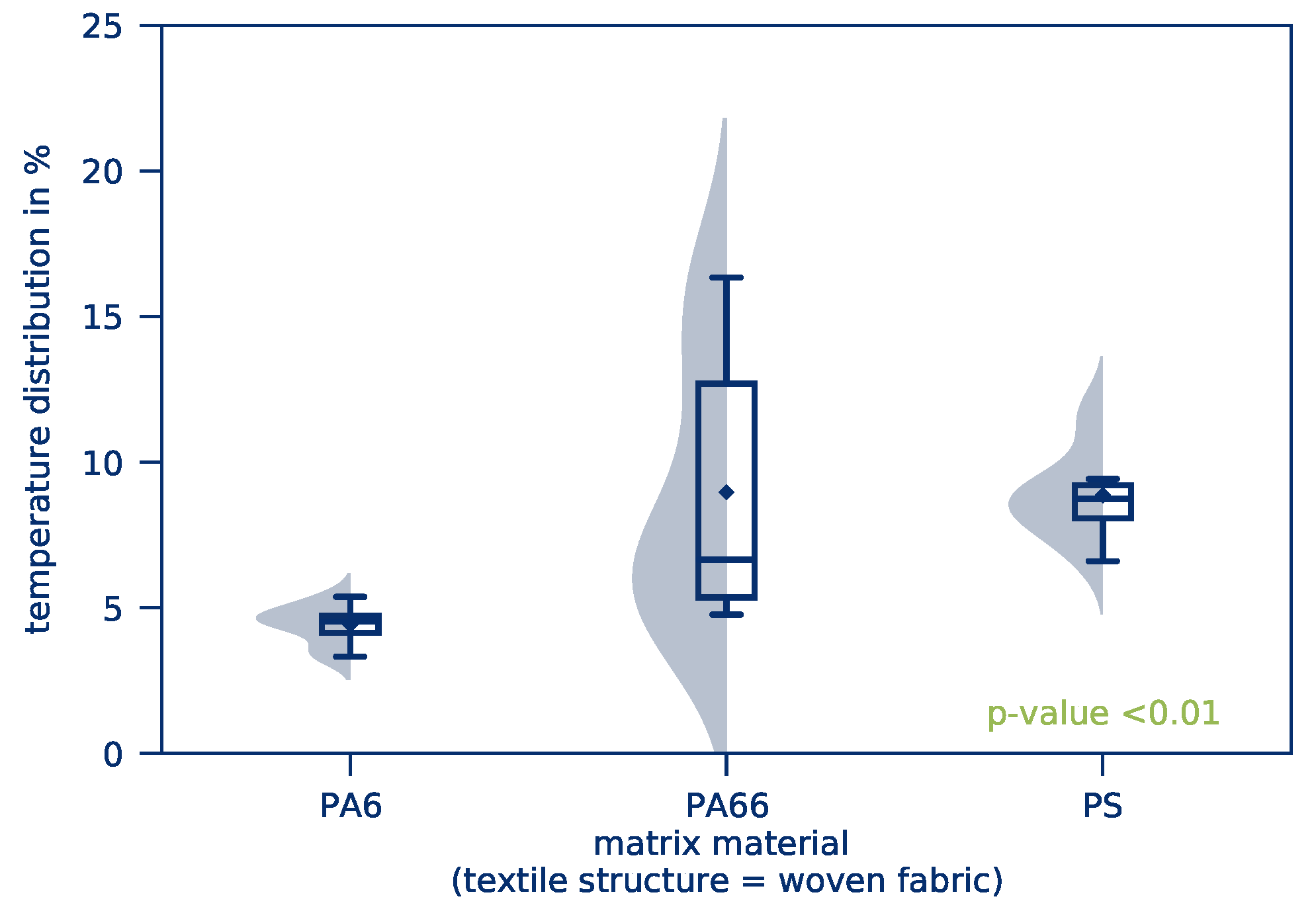
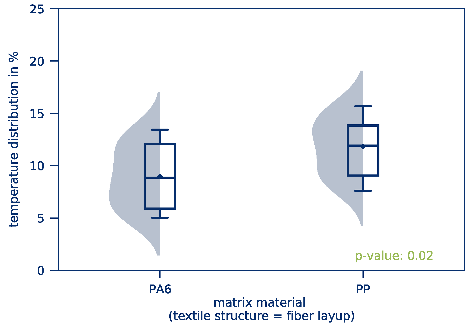
3.1.2. Influence of Textile Structure and Matrix Material on the Heating Behavior
3.1.3. Influence of the Part’s Size on Heating Behavior
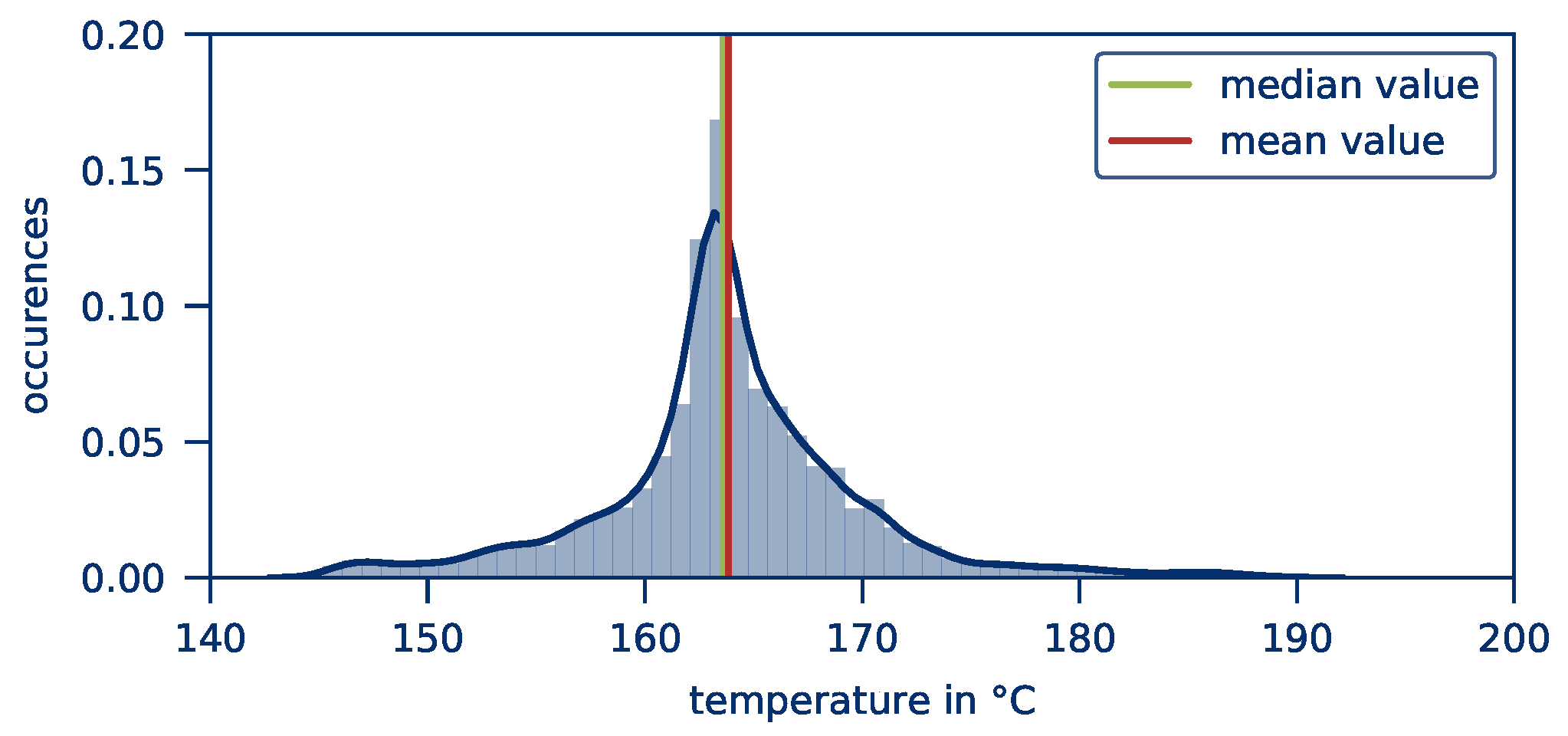
3.2. Evaluation Algorithms and Methods
4. Results
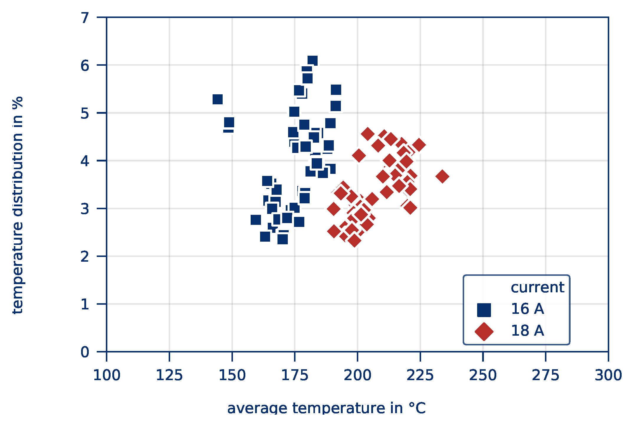
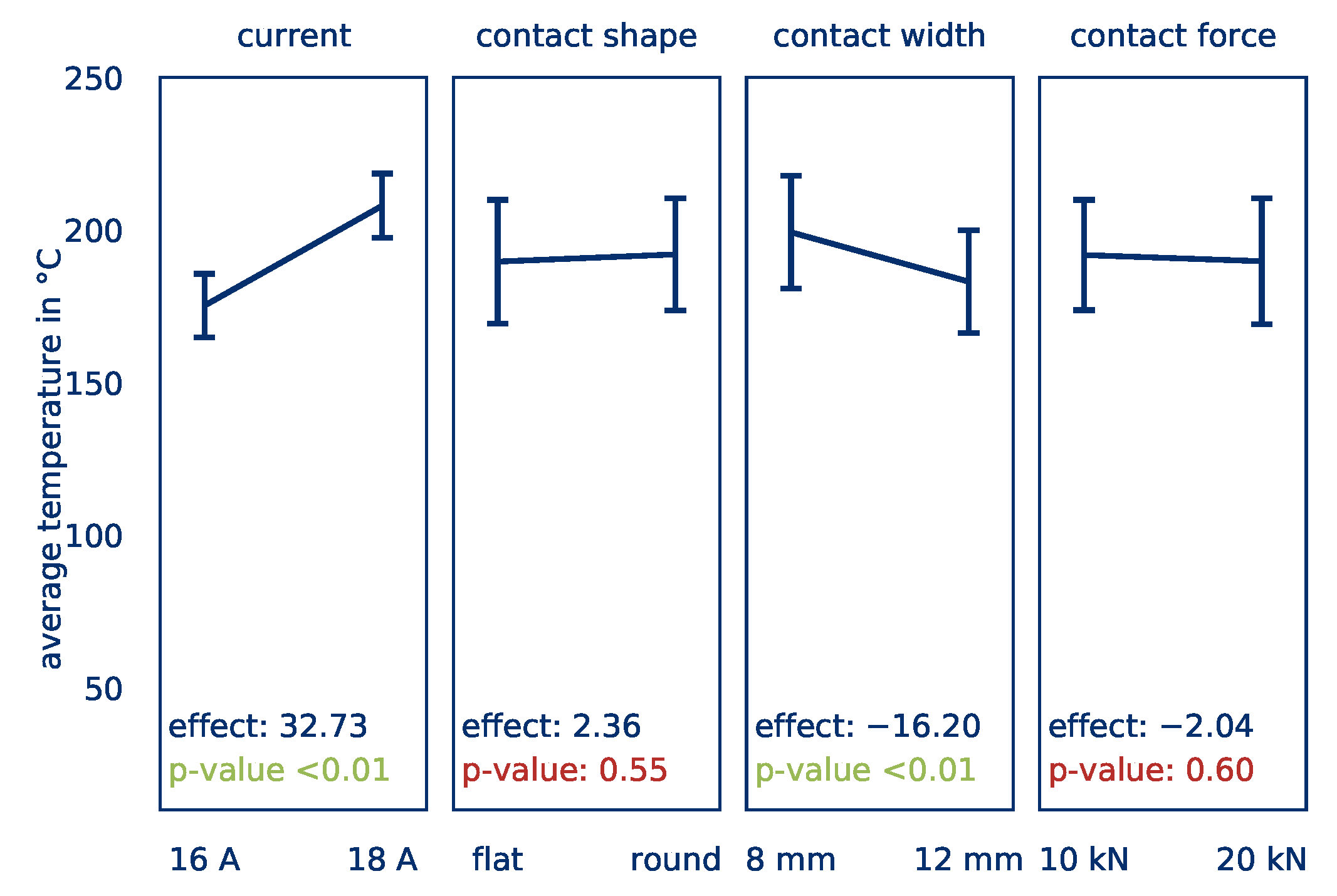
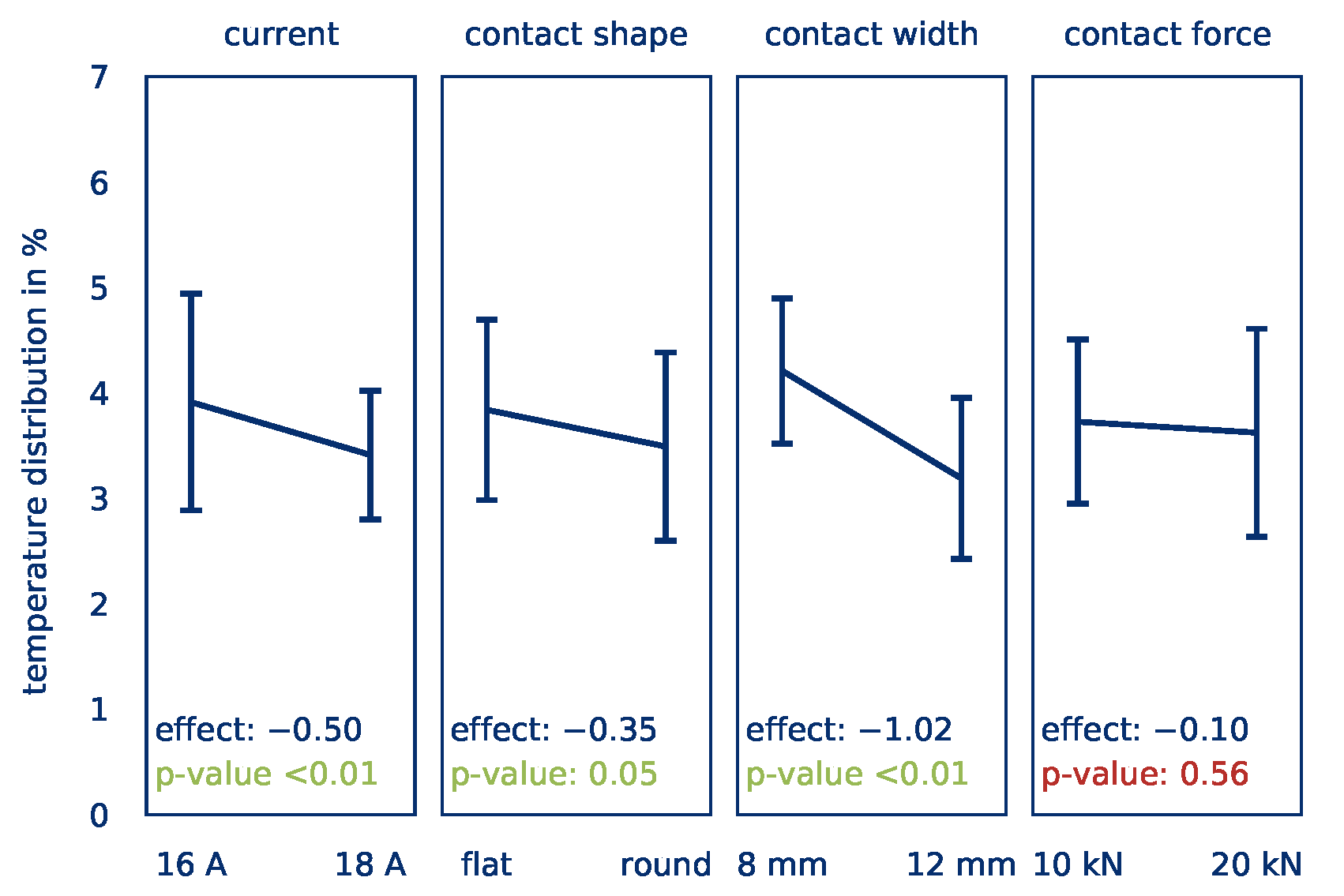
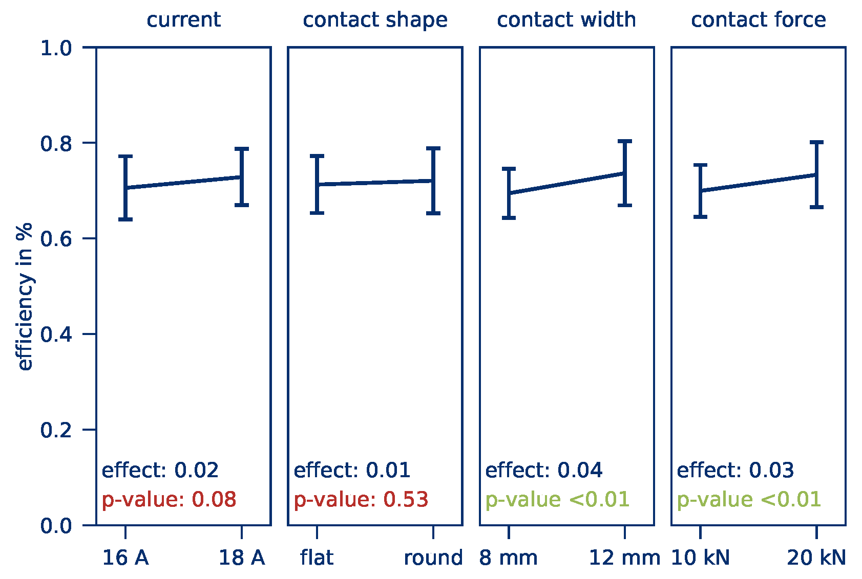
4.1. Influence of the Contacting on the Heating Behavior
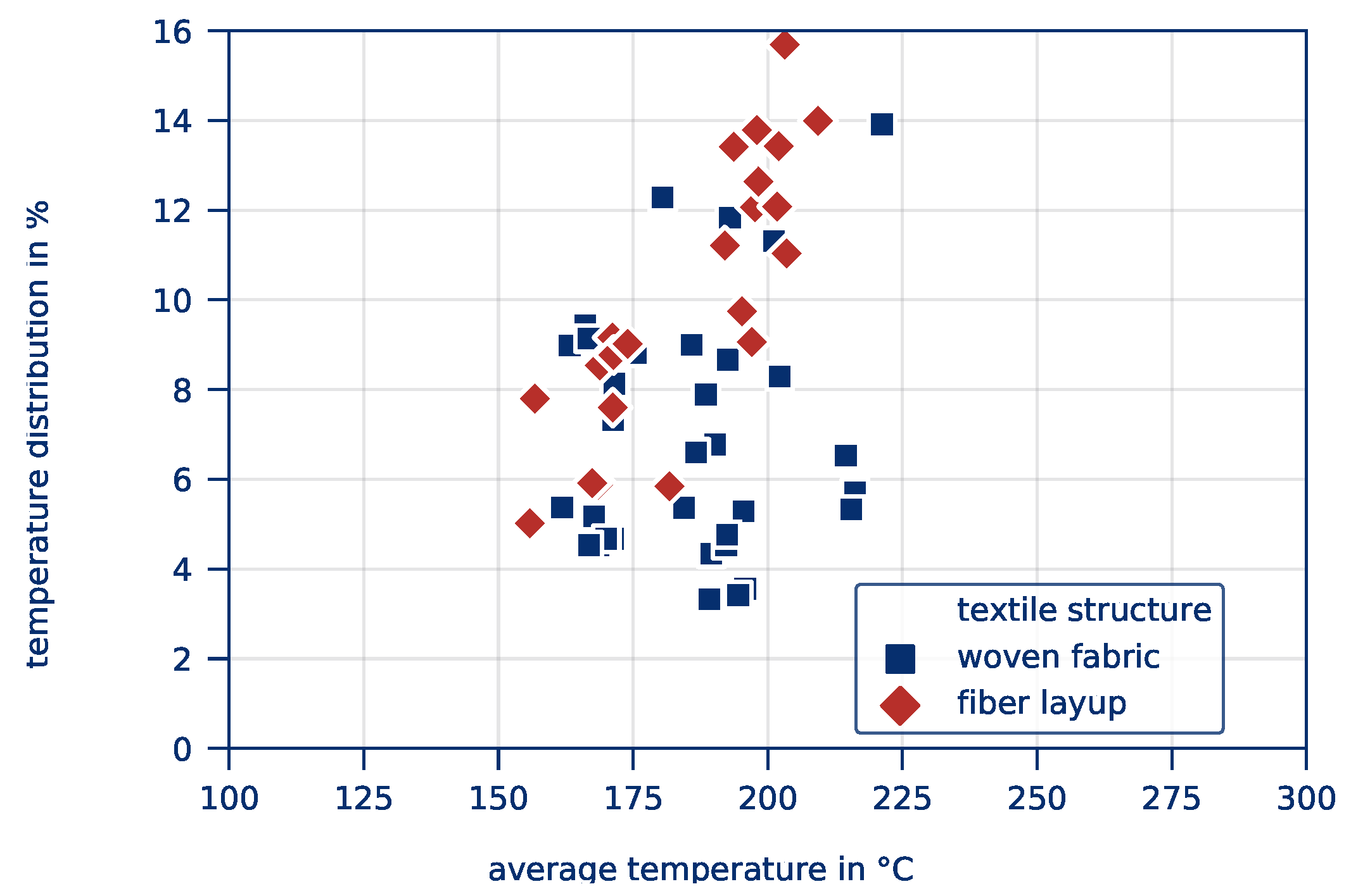
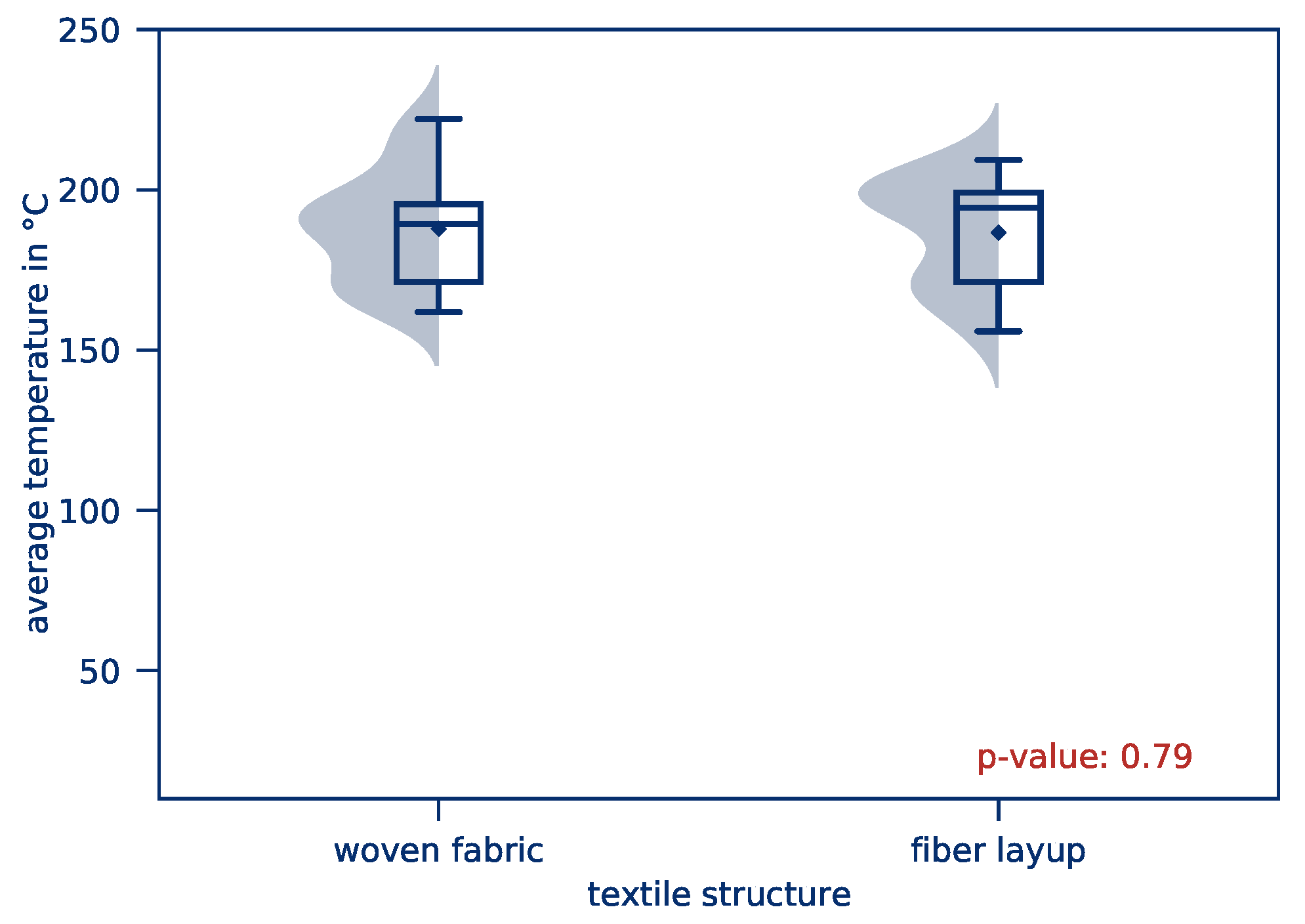
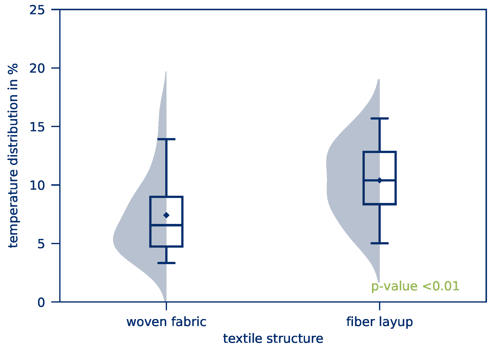
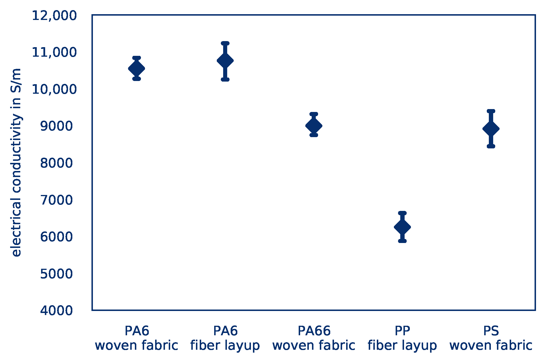
4.2. Influence of the Material on Heating Behavior
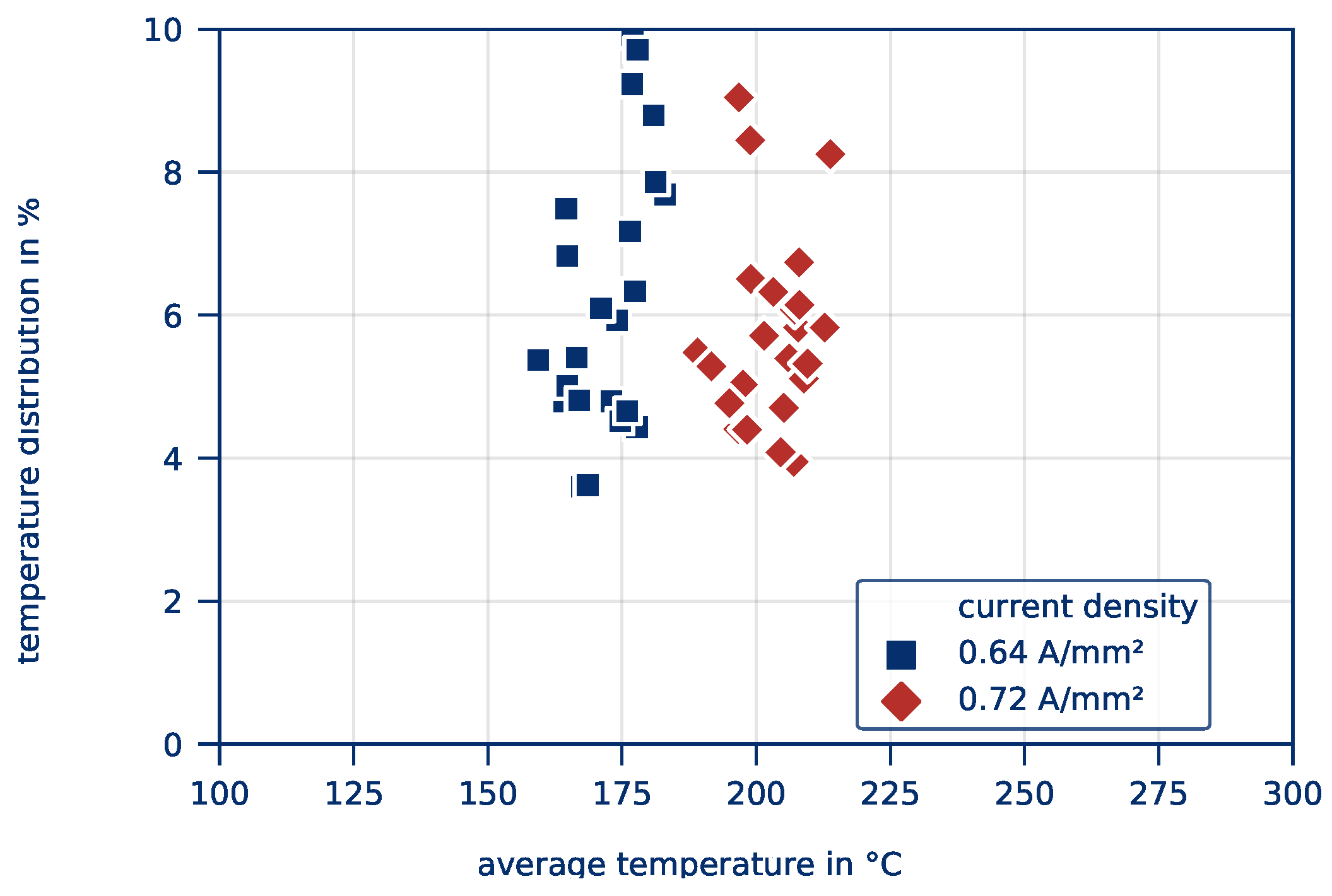
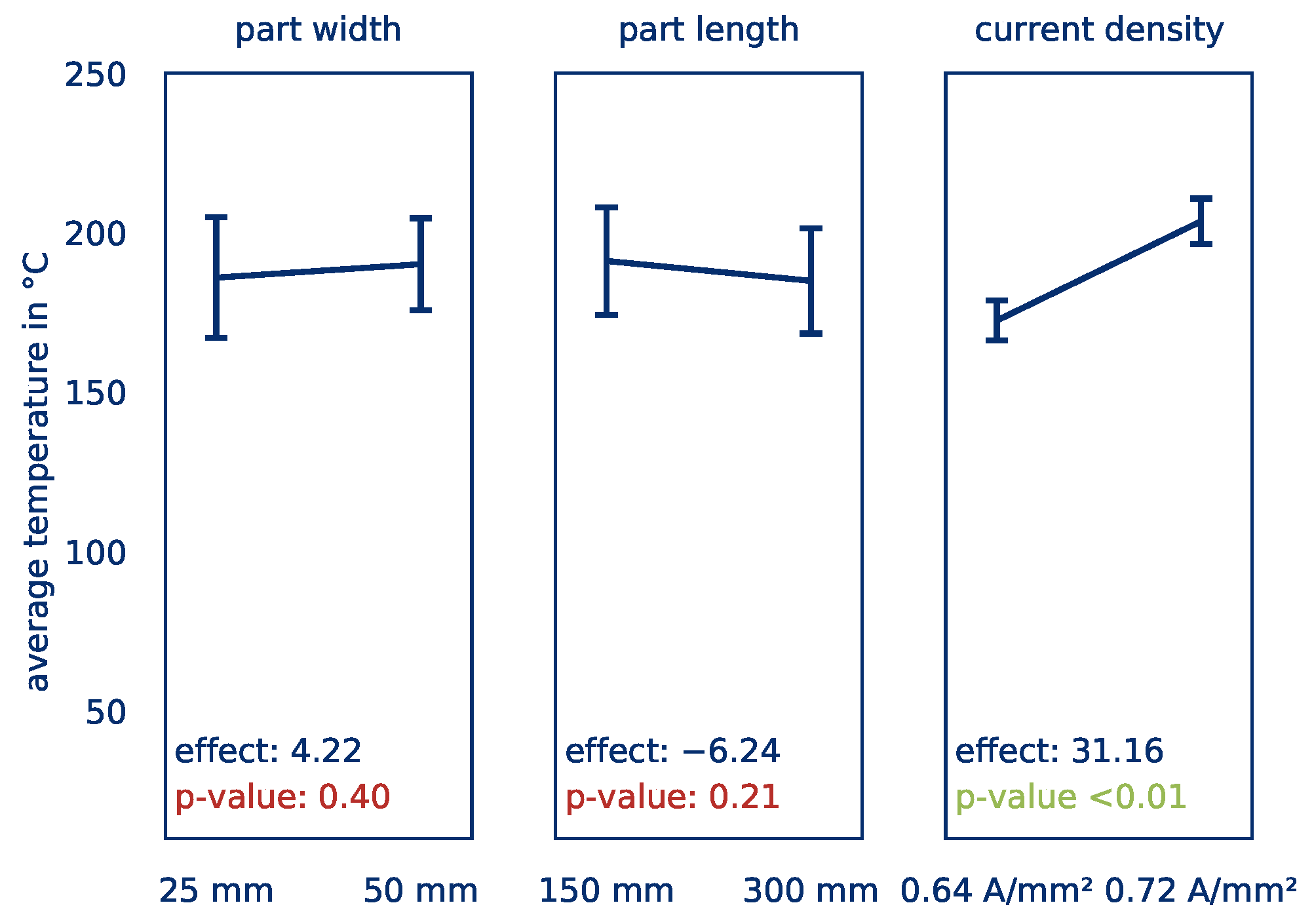
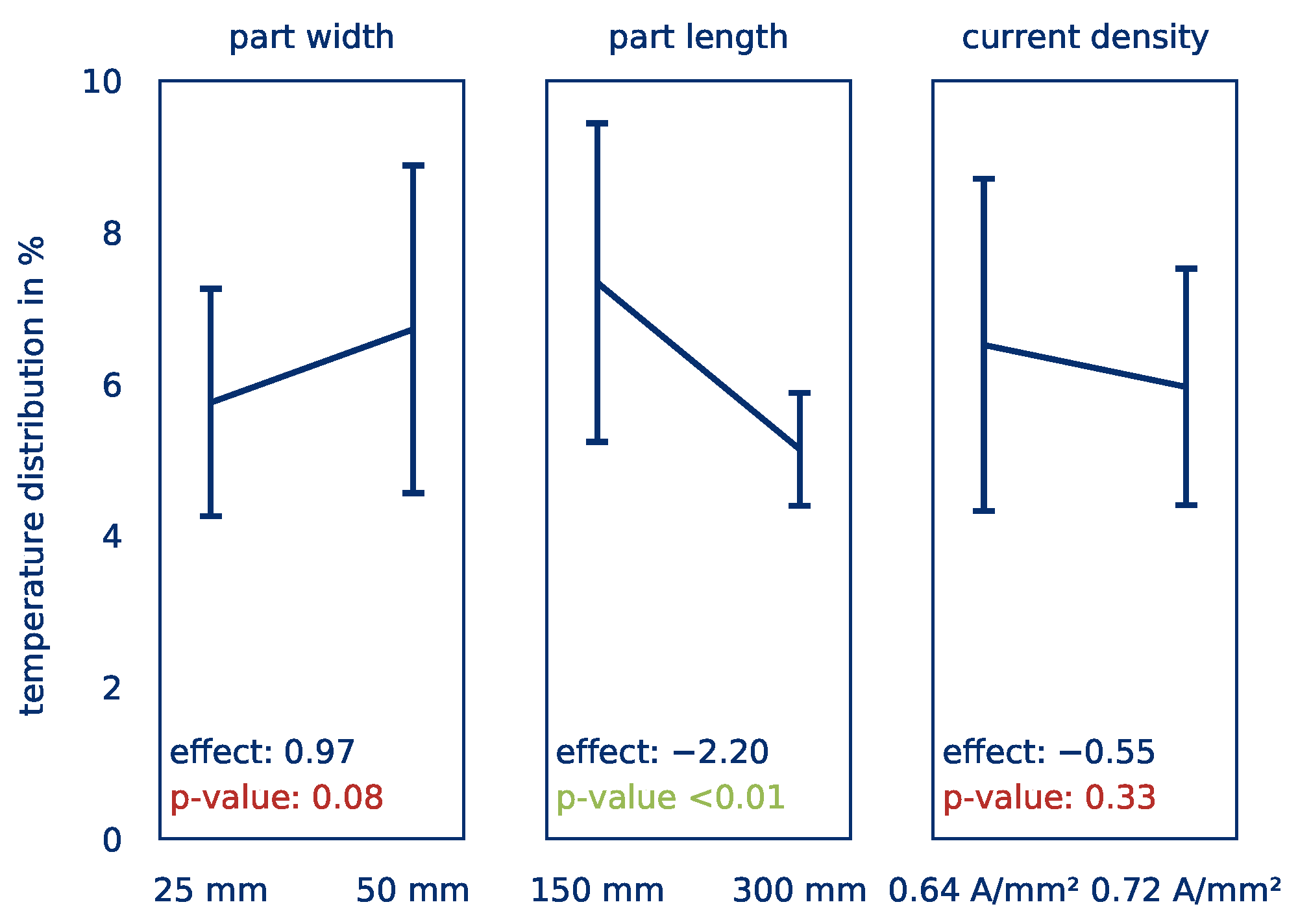
4.3. Influence of the Part’s Size on the Heating Behavior
5. Conclusions
Author Contributions
Funding
Acknowledgments
Conflicts of Interest
References
- Bosch, R. Bosch Automotive Handbook; SAE International: Warrendale, PA, USA, 2018. [Google Scholar]
- Braess, H.H.; Seiffert, U. Vieweg Handbuch Kraftfahrzeugtechnik; Springer: Wiesbaden, Germany, 2013. [Google Scholar] [CrossRef]
- Bonten, C. Plastics Technology: Introduction and Fundamentals; Hanser: Munich, Germany, 2019. [Google Scholar]
- Neitzel, M.; Mitschang, P.; Breuer, U. Handbuch Verbundwerkstoffe: Werkstoffe, Verarbeitung, Anwendung; Hanser: München, Germany, 2014. [Google Scholar]
- Hopmann, C.; Michaeli, W. Einführung in die Kunststoffverarbeitung; Hanser: München, Germany, 2015. [Google Scholar]
- Bürkle, E.; Wobbe, H. Kombinationstechnologien auf Basis des Spritzgießverfahrens; Hanser: München, Germany, 2016. [Google Scholar]
- Malek, T. Trends und Entwicklungen in der Hybridtechnik. Lightweight Des. 2012, 5, 20–23. [Google Scholar] [CrossRef]
- Müller, T. Methodik zur Entwicklung von Hybridstrukturen auf Basis faserverstärkter Thermoplaste; Universität Erlangen-Nürnberg: Erlangen, Germany, 2011. [Google Scholar]
- Müller, T.; Drummer, D. Process Combinations as a Key for Producing Lightweight and High-duty Composite Structures Based on Thermoplastic Materials. In Proceedings of the European Conference on Composite Materials 15, Venice, Italy, 24–28 June 2012. [Google Scholar]
- Linn, C.; Hoffmann, L.; Müller, T.; Drummer, D. Herstellung von CFK-Bauteilen durch Direktimprägnierung mit Thermoplasten in der Spritzgießmaschine. Lightweight Des. 2012, 5, 56–61. [Google Scholar] [CrossRef]
- Cherif, C. Textile Materials for Lightweight Construction; Springer: Berlin/Heidelberg, Germany, 2011. [Google Scholar] [CrossRef]
- Wellekötter, J.; Baz, S.; Schwingel, J.; Gresser, G.T.; Middendorf, P.; Bonten, C. Recycling of composites—A new approach minimizes downgrading. Proc. Polym. Process. Soc. 2017, 31. [Google Scholar] [CrossRef]
- Reddemann, J. Beitrag zum energieeffizienten Einsatz von Thermoplast-CFK im Automobilbau; Universität Erlangen-Nürnberg: Erlangen, Germany, 2016. [Google Scholar]
- Azenha, J.; Gomes, M.; Silva, P.; Pontes, A.J. High strength injection molded thermoplastic composites. Polym. Eng. Sci. 2018, 58, 560–567. [Google Scholar] [CrossRef]
- Lück, A.; Drummer, D.; Hoffmann, L. Thermoplastische Hochleistungsfaserverbunde mit erweiterter Funktionalität. In Proceedings of the Fachtagung Thermoplastische Faserverbundkunststoffe, Dresden, Germany, 15–16 May 2013. [Google Scholar]
- Brockmann, C.; Aengenheyster, G. Verst ärken von Spritzgegossenen Formteilen durch Endlosfaserverstärkte Thermoplastische Prepregs. Final Project Report, Grant Number AiF 10053. 1996; Unpublished work. [Google Scholar]
- Hildebrandt, M. Serienfähiger Leichtbau mit Thermoplasten. Kunststoffe. October 2015, pp. 118–122. Available online: https://www.kunststoffe.de/kunststoffe-zeitschrift/archiv/artikel/neue-entwicklungen-bei-duroplastischen-und-thermoplastischen-faserverbundkunststoffen-1097000.html (accessed on 10 December 2020).
- Pfefferkorn, T. From Laminate to Component. Kunststoffe Int. 2013, 12, 70–76. [Google Scholar]
- Cetin, M.; Herrmann, C.; Fenske, S. Automatisierungskonzepte zur Herstellung faserverstärkter Thermoplastbauteile. Lightweight Des. 2017, 10, 38–43. [Google Scholar] [CrossRef]
- Rettenwander, T.; Zwicklhuber, P.; Fischlschweiger, M.; Steinbichler, G. Maßgeschneiderte Composites für hohe Stückzahlen. Kunststoffe. October 2014, pp. 138–143. Available online: https://www.kunststoffe.de/kunststoffe-zeitschrift/archiv/artikel/das-tape-lege-verfahren-kombiniert-organobleche-und-tapes-inline-und-senkt-gewicht-und-kosten-der-bauteile-910952.html (accessed on 10 December 2020).
- Kawan, I. Airbag housing in nylon composite sheet hybrid technology. Lanxess Press Release, 20 March 2012. [Google Scholar]
- Panzer, U. Industry experts duscussed the future of lightweight construction. Engel Press Release, 19 June 2019. [Google Scholar]
- Cetin, M.; Herrmann, C.; Schierl, S. Hochdynamisches und homogenes Aufheizen von Organoblechen. Lightweight Des. 2017, 10, 54–61. [Google Scholar] [CrossRef]
- Thurmeier, M.; Stock, A.; Fischlschweiger, M. Heiztechnik als Schlüsselfaktor: Leichtbau mit thermoplastischen FKV erfordert neueWege in der Verarbeitung. Kunststoffe. June 2014, pp. 66–69. Available online: https://www.engelglobal.com/fileadmin/master/Downloads/Fachartikel/2014_06_Kunststoffe_Heiztechnik_Schluesselfaktor.pdf (accessed on 10 December 2020).
- Brinken, F. Untersuchung zur Wärmeübertragung beim Thermoformen von Thermoplasten. P.hD. Thesis, RWTH Aachen, Aachen, Germany, 1979. [Google Scholar]
- Joule, J.P. On the mechanical equivalent of heat. Proc. R. Soc. 1850, 140, 61–82. [Google Scholar] [CrossRef]
- Pappadà, S.; Salomi, A.; Montanaro, J.; Passaro, A.; Caruso, A.; Maffezzoli, A. Fabrication of a thermoplastic matrix composite stiffened panel by induction welding. Aerosp. Sci. Technol. 2015, 43, 314–320. [Google Scholar] [CrossRef]
- Ahmed, T.J.; Stavrov, D.; Bersee, H.; Beukers, A. Induction welding of thermoplastic composites—An overview. Compos. Part Appl. Sci. Manuf. 2006, 37, 1638–1651. [Google Scholar] [CrossRef]
- Kupke, M.; Schulte, K.; Schüler, R. Non-destructive testing of FRP by d.c. and a.c. electrical methods. Compos. Sci. Technol. 2001, 61, 837–847. [Google Scholar] [CrossRef]
- Ageorges, C.; Ye, L.; Hou, M. Experimental investigation of the resistance welding for thermoplastic-matrix composites. Part I: Heating element and heat transfer. Compos. Sci. Technol. 2000, 60, 1027–1039. [Google Scholar] [CrossRef]
- Becker, S.; Mitschang, P. CF-verstärkte Kunststoffe induktiv erwärmen: Einflüsse der Laminatparameter auf das induktive Aufheizverhalten von CFK. Kunststoffe. September 2018, pp. 117–121. Available online: https://www.kunststoffe.de/kunststoffe-zeitschrift/archiv/artikel/einfluesse-der-laminatparameter-auf-das-induktive-aufheizverhalten-von-cfk-6282381.html (accessed on 10 December 2020).
- Endraß, M.; Gänswürger, P.; Jarka, S.; Bauer, S.; Fischer, F.; Ziche, L.; Larsen, L.C.; Kupke, M. Towards increased reliability of resistance welded joints for aircraft assembly. In Proceedings of the ITHEC international Conference, Bremen, Germany, 13–14 October 2020. [Google Scholar]
- Hemmen, A. Direktbestromung von Kohlenstofffasern zur Minimierung von Zykluszeit und Energieaufwand bei der Herstellung von Karbonbauteilen. Ph.D. Thesis, Universität Augsburg, Augsburg, Germany, 2016. [Google Scholar]
- Reese, J.; Hoffmann, G.; Fieres, J.; Cherif, C. Characterization of the electrical behavior of a discontinuous hybrid yarn textile made of recycled carbon and PA6 fibers during Joule heating. J. Thermoplast. Compos. Mater. 2020, 33. [Google Scholar] [CrossRef]
- Reese, J.; Vorhof, M.; Hoffmann, G.; Böhme, K.; Cherif, C. Joule heating of dry textiles made of recycled carbon fibers and PA6 for the series production of thermoplastic composites. J. Eng. Fibers Fabr. 2020, 15. [Google Scholar] [CrossRef] [Green Version]
- Romanov, S.A.; Alekseeva, A.A.; Khabushev, E.M.; Krasnikov, D.V.; Nasibulin, A.G. Rapid, efficient, and non-destructive purification of single-walled carbon nanotube films from metallic impurities by Joule heating. Carbon 2020, 168, 193–200. [Google Scholar] [CrossRef]
- Jang, S.H.; Kim, D.; Park, Y.L. Accelerated Curing and Enhanced Material Properties of Conductive Polymer Nanocomposites by Joule Heating. Materials 2018, 11, 1775. [Google Scholar] [CrossRef] [Green Version]
- Koslowski, T.; Bonten, C. Resistance Heating of Continuous Reinforced Thermoplastics. In Proceedings of the Proceedings of the Polymer Processing Society Annual Meeting, Nuremberg, Germany, 15–19 July 2013; Volume 29. [Google Scholar]
- Geyer, A.; Koslowski, T.; Bonten, C. Influence of the heating process on the mechanical properties of continuous reinforced thermoplastics. Proc. Polym. Process. Soc. 2015, 29. [Google Scholar] [CrossRef] [Green Version]
- Wellekötter, J. Resistance Heating of Carbon Fiber Reinfroced Thermoplastics. In Proceedings of the SPE ANTEC Annual Conference 2019, Detroit, MI, USA, 17–21 March 2019. [Google Scholar]
- Klemt, M.; Binjung, B.; Geier, S.; Bonten, C. Insitu-Aufheizung von CFK-Organoblechen. Kunststoffe. November 2011, pp. 78–82. Available online: https://kunststoffe-live.censhare.de/kunststoffe-zeitschrift/archiv/artikel/verbundwerkstoffe-in-situ-aufheizung-von-cfk-organoblechen-535732.html?search.highlight=Insitu-Aufheizung%20von%20CFK-Organobleche (accessed on 10 December 2020).
- Bond Laminates GmbH, Brilon, Germany: Tepex Dynalite 201-C200. Available online: https://bond-laminates.com/en/downloads/data-sheets/ (accessed on 10 December 2020).
- Wickham, H. Tidy Data. J. Stat. Softw. 2014, 59. [Google Scholar] [CrossRef] [Green Version]
- Fisher, R.A. The Design of Experiments; Oliver & Boyd: Edinburgh, UK, 1935. [Google Scholar]
- Brunner, F.J. Versuchsplanung: Produkte und Prozesse Optimieren; Hanser: München, Germany, 2016. [Google Scholar]
- Wellekötter, J. The Joule Heating of Carbon Fiber Reinforced Thermoplastics. Ph.D. Thesis, Universität Stuttgart, Stuttgart, Germany, 2020. [Google Scholar]
- Deutsches Institut für Normung e.V. DIN EN ISO 527-4: Kunststoffe—Bestimmung der Zugeigenschaften—Teil 4: Prüfbedingungen für Isotrop und Anisotrop faserverstärkte Kunststoffverbundwerkstoffe; Deutsches Institut für Normung e.V.: Berlin, Germany, 1997. [Google Scholar]
- Fisher, R.A. Statistical Methods for Research Workers; Oliver & Boyd: Edinburgh, UK, 1925. [Google Scholar]
- Savitzky, A.; Golay, M.J.E. Smoothing and Differentiation of Data by Simplified Least Squares Procedures. Anal. Chem. 1964, 36, 1627–1639. [Google Scholar] [CrossRef]
- Deutsches Institut für Normung e.V. DIN EN ISO 6946: Bauteile—Wärmedurchlasswiderstand und Wärmedurchgangskoeffizient—Berechnungsverfahren; Deutsches Institut für Normung e.V.: Berlin, Germany, 2018. [Google Scholar]
- Eyerer, P.; Elsner, P.; Hirth, T. Die Kunststoffe und ihre Eigenschaften; VDI-Buch; Springer: Berlin/Heidelberg, Germany, 2005. [Google Scholar]


| Factor | Setting − | Setting + |
|---|---|---|
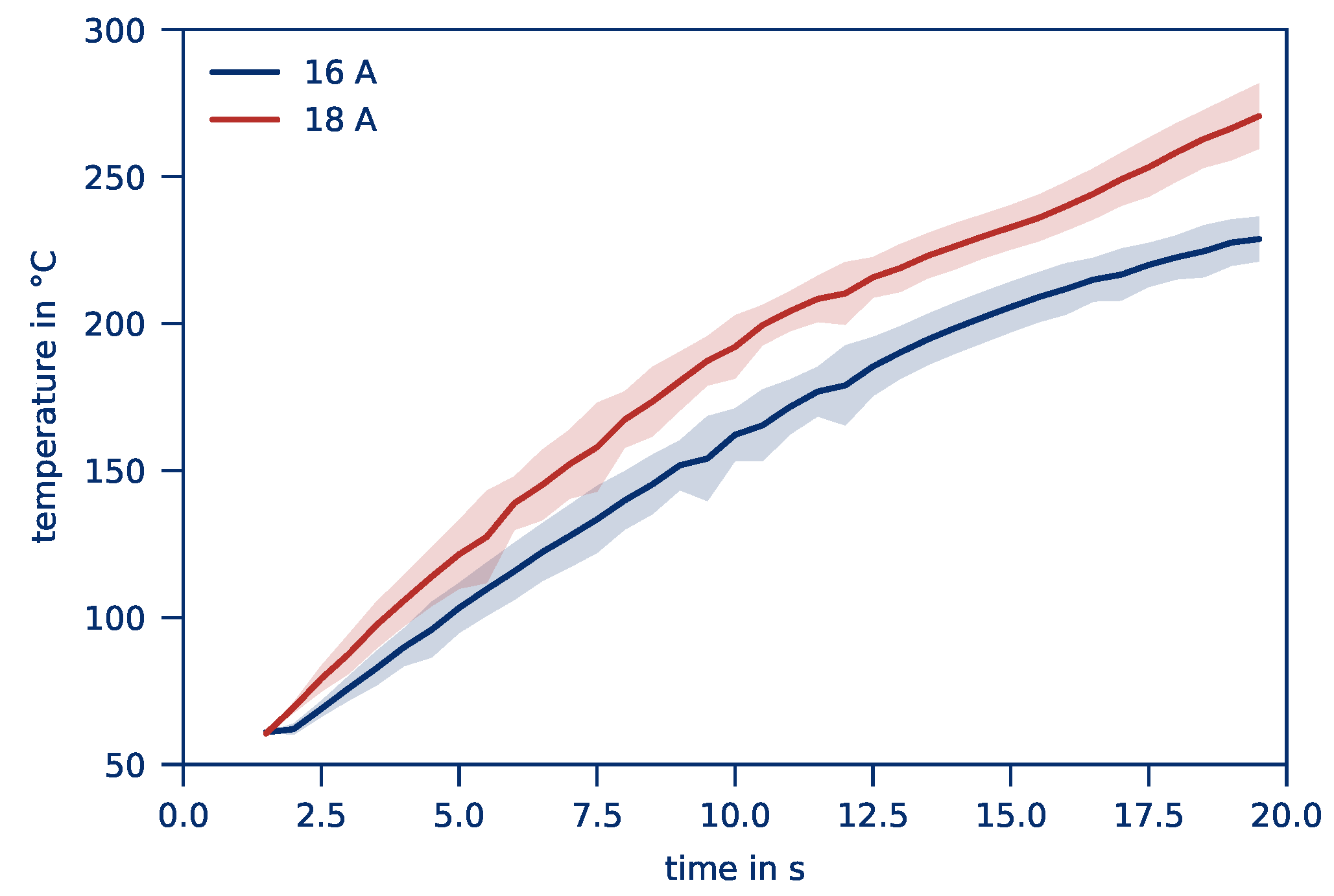
| Current I in A | 16 | 18 |
| Contact force F in kN | 10 | 20 |
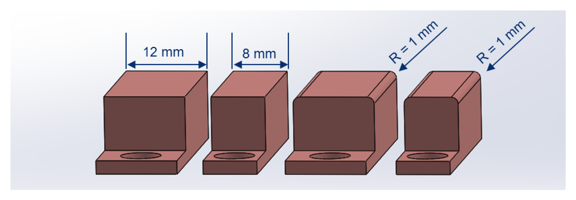
| Contact width b in mm | 8 | 12 |
| Contact shape O | flat | rounded |
| Producer | Textile Structure | Matrix Material |
|---|---|---|
| Bond Laminates | Woven fabric | PA66 |
| Bond Laminates | Woven fabric | PA6 |
| SGL Carbon | Tape based | PA6 |
| SGL Carbon | Tape based | PP |
| Ineos Styrolution | Woven fabric | PS |
| Factor | Setting − | Setting + |
|---|---|---|
| Current density J in A/mm | 0.64 | 0.72 |
| Part length L in mm | 150 | 300 |
| Part width B in mm | 25 | 50 |
| Target Value | Effect | Current | Contact Shape | Contact Width | Contact Force |
|---|---|---|---|---|---|
| average part temperature | 32.73 | 2.36 | −16.20 | −2.04 | |
| temperature distribution | −0.5 | −0.35 | −1.02 | −0.1 | |
| efficiency | 0.02 | 0.01 | 0.04 | 0.03 |
| Target Value | Effect | Part Width | Part Length | Current Density |
|---|---|---|---|---|
| average part temperature | 4.22 | −6.24 | 31.16 | |
| temperature distribution | 0.97 | −2.2 | −0.55 |
Publisher’s Note: MDPI stays neutral with regard to jurisdictional claims in published maps and institutional affiliations. |
© 2020 by the authors. Licensee MDPI, Basel, Switzerland. This article is an open access article distributed under the terms and conditions of the Creative Commons Attribution (CC BY) license (http://creativecommons.org/licenses/by/4.0/).
Share and Cite
Wellekötter, J.; Bonten, C. Direct Joule Heating as a Means to Efficiently and Homogeneously Heat Thermoplastic Prepregs. Polymers 2020, 12, 2959. https://doi.org/10.3390/polym12122959
Wellekötter J, Bonten C. Direct Joule Heating as a Means to Efficiently and Homogeneously Heat Thermoplastic Prepregs. Polymers. 2020; 12(12):2959. https://doi.org/10.3390/polym12122959
Chicago/Turabian StyleWellekötter, Jochen, and Christian Bonten. 2020. "Direct Joule Heating as a Means to Efficiently and Homogeneously Heat Thermoplastic Prepregs" Polymers 12, no. 12: 2959. https://doi.org/10.3390/polym12122959