Polyetheretherketone and Its Composites for Bone Replacement and Regeneration


Abstract
:1. Introduction
2. PEEK Implants
2.1. Coatings
2.1.1. Hydroxyapatite-Coated PEEK Implants
2.1.2. Ti-Coated PEEK Implants
2.1.3. TiO2-Coated PEEK Implants
3. PEEK-Based Microcomposites
3.1. PEEK/HA Microcomposites
3.2. PEEK/Carbon Fiber Microcomposites
PEEK/CF Hip Prostheses
4. PEEK-Based Nanocomposites
4.1. PEEK-nHA Nanocomposites
4.2. PEEK-Metal Oxide Nanocomposites
4.3. PEEK-CNT Nanocomposites
5. Hybrid Composites
5.1. PEEK-nHA-MWNT Hybrids
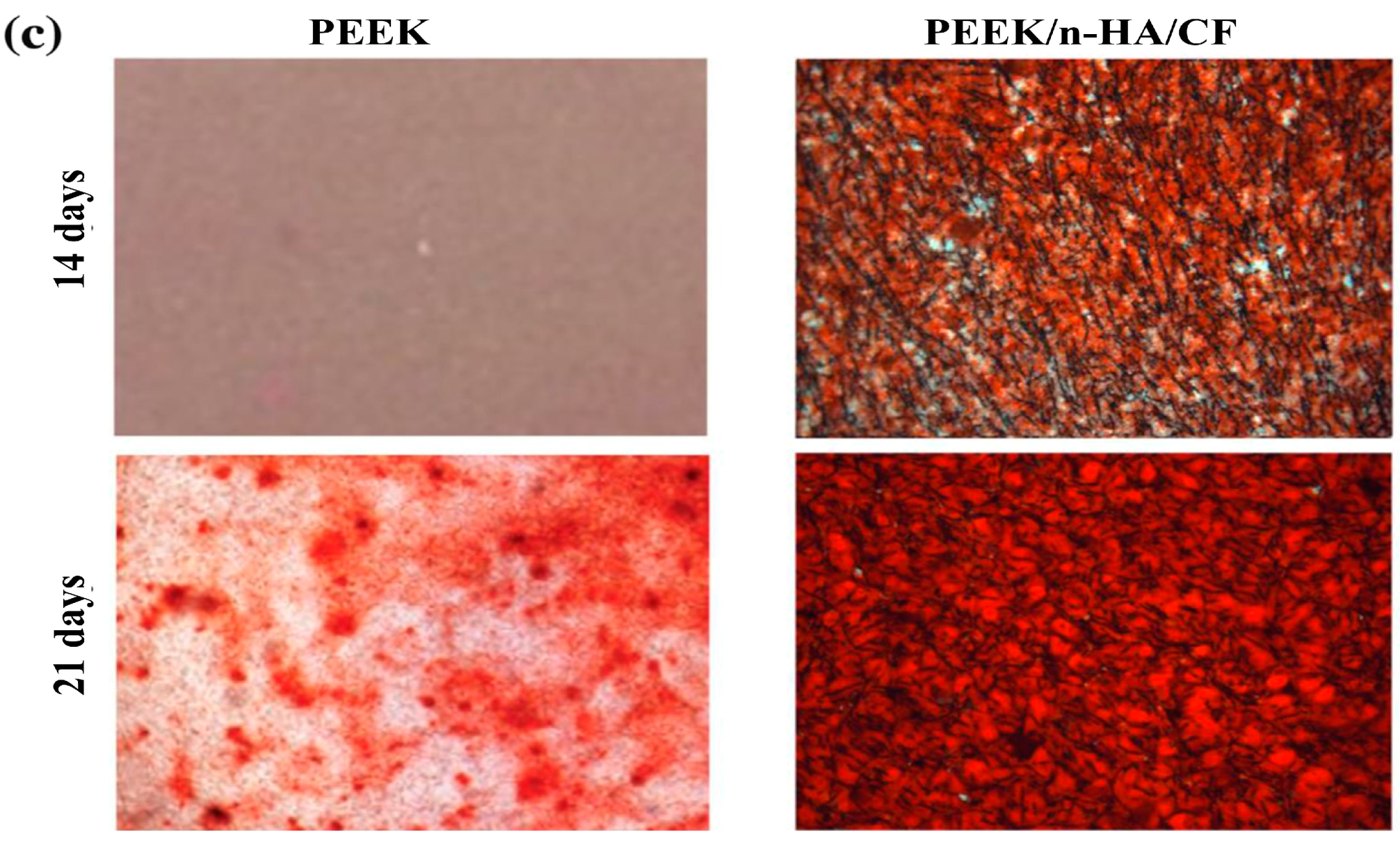
5.2. PEEK-nHA-CF Hybrids
6. Scaffolds for Soft Tissue Engineering
Biodegradable PEEK Blend Scaffolds
7. Future Prospects and Challenges
8. Conclusions
Author Contributions
Funding
Conflicts of Interest
Abbreviations
| ACDF | Anterior cervical discectomy and fusion |
| AIP | Arc ion plating |
| ALP | Alkaline phosphatase |
| AM | Additive manufacturing |
| APTMS | Anilinopropyltrimethoxysilane |
| BIC | Bone implant contact |
| BMP-2 | Bone morphogenetic protein-2 |
| CAD | Computer aided design |
| CAM | Computer aided manufacturing |
| CF | Carbon fiber |
| CLSM | Confocal laser scanning microscopy |
| CNF | Carbon nanofiber |
| CNT | Carbon nanotube |
| COL1 | Collagen type 1 |
| CS | Calcium silicate |
| CT | Computed tomography |
| ECM | Extracellular matrix |
| FDM | Fused deposition modeling |
| FFF | Fused filament fabrication |
| GO | Graphene oxide |
| HA | Hydroxyapatite |
| HDPE | High-density polyethylene |
| hMSC | Human mesenchymal stem cell |
| HPEEK | Heat-treated PEEK |
| IBAD | Ion beam assisted deposition |
| IPD | Ionic plasma deposition |
| MC3T3-E1 | Murine pre-osteoblastic cell |
| MG63 | Human osteoblast-like osteosarcoma cell |
| mHA | Hydroxyapatite microparticle |
| MTT | [3-(4,5-dimethylthiazol-2-yl)-2,5-diphenyltetrazolium bromide] |
| MWNT | Multiwalled carbon nanotube |
| nHA | Nanohydroxyapatite |
| NP | Nanoparticle |
| OPN | Osteopontin |
| PAN | Polyacrylonitrile |
| PBS | Phosphate-buffered saline |
| PEEK | Polyetheretherketone |
| PIII | Plasma immersion ion implantation |
| PGA | Polyglycolic acid |
| PLIF | Posterior lumbar interbody fusion |
| PSI | Patient specific implant |
| PVA | Polyvinyl alcohol |
| ROS | Reactive oxygen species |
| SBF | Simulated body fluid |
| SCF | Short carbon fiber |
| SHPEEK | Sulfonated PEEK |
| SLS | Selective laser sintering |
| SWNT | Single walled carbon nanotube |
| UHMWPE | Ultra-high molecular weight polyethylene |
| UV | Ultraviolet |
| VGCNF | Vapor grown carbon nanofiber |
| VPS | Vacuum plasma spraying |
| WST-1 | 2-(4-iodophenyl)-3-(4-nitrophenyl)-5-(2,4-disulfophenyl)-2H-tetrazolium |
| YSZ | Yttria-stabilized zirconia |
References
- Mauffrey, C.; Barlow, B.T.; Smith, W. Management of segmental bone defects. J. Am. Acad. Orthop. Surg. 2015, 23, 143–153. [Google Scholar] [CrossRef]
- Velu, R.; Calais, T.; Jayakumar, A.; Raspall, F. A comprehensive review on bio-nanomaterials for medical implants and feasibility studies on fabrication of such implants by additive manufacturing technique. Materials 2020, 13, 92. [Google Scholar] [CrossRef] [Green Version]
- Eliaz, N.; Metoki, N. Calcium phosphate bioceramics: A review of their history, structure, properties, coating technologies and biomedical applications. Materials 2017, 10, 334. [Google Scholar] [CrossRef] [Green Version]
- Lu, J.; Yu, H.; Chen, C. Biological properties of calcium phosphate biomaterials for bone repair: A review. RSC Adv. 2018, 8, 2015–2033. [Google Scholar] [CrossRef] [Green Version]
- Gibon, E.; Amanatullah, D.F.; Loi, F.; Pajarinen, J.; Nabeshima, A.; Yao, Z.; Hamadouche, M.; Goodman, S.B. The biological response to orthopaedic implants for joint replacement: Part I: Metals. J. Biomed. Mater. Res. B Appl. Biomater. 2017, 105, 2162–2173. [Google Scholar] [CrossRef]
- Ohrt-Nissen, S.; Dahl, B.; Gehrchen, M. Choice of rods in surgical treatment of adolescent idiopathic scoliosis: What are the clinical implications of biomechanical properties?—A review of the literature. Neurospine 2018, 15, 123–130. [Google Scholar] [CrossRef] [Green Version]
- Prasad, K.; Bazaka, O.; Chua, M.; Rochford, M.; Fedrick, L.; Spoor, J.; Symes, R.; Tieppo, M.; Collins, C.; Cao, A.; et al. Metallic biomaterials: Current challenges and opportunities. Materials 2017, 10, 884. [Google Scholar] [CrossRef] [PubMed]
- Heary, R.F.; Parvathreddy, N.; Sampath, S.; Argarwal, N. Elastic modulus in the selection of interbody implants. J. Spine Surg. 2017, 3, 163–167. [Google Scholar] [CrossRef] [PubMed] [Green Version]
- Wang, M.; Ladizesky, N.H.; Tanner, K.E.; Ward, I.M.; Bonfield, W. Hydrostatically extruded HAPEXTM. J. Mater. Sci. 2000, 35, 1023–1030. [Google Scholar] [CrossRef]
- Nag, S.; Banerjee, R. Fundamentals of medical implant materials. In ASM Handbook, Materials for Medical Devices; Narayan, R., Ed.; ASM International: Materials Park, OH, USA, 2012; Volume 23, pp. 6–17. [Google Scholar]
- Okazaki, Y.; Gatoh, E. Comparison of metal release from various metallic biomaterials in vitro. Biomaterials 2005, 26, 11–21. [Google Scholar] [CrossRef] [PubMed]
- Scharf, B.; Clement, C.C.; Zolla, V.; Perino, G.; Yan, B.; Elci, S.G.; Purdue, E.; Goldring, S.; Macaluso, F.; Cobelli, N.; et al. Molecular analysis of chromium and cobalt-related toxicity. Sci. Rep. 2014, 4, 5729. [Google Scholar] [CrossRef] [PubMed] [Green Version]
- Tjong, S.C.; Hoffman, R.W.; Yeager, E.B. Electron and ion spectroscopic studies of the passive film on iron-chromium alloys. J. Electrochem. Soc. 1982, 129, 1662–1668. [Google Scholar] [CrossRef]
- Tjong, S.C.; Yeager, E. ESCA and SIMS studies of the passive film on iron. J. Electrochem. Soc. 1981, 128, 2251–2254. [Google Scholar] [CrossRef]
- Ulery, B.D.; Nair, L.S.; Laurencin, C.T. Biomedical applications of biodegradable polymers. J. Polym. Sci. B Polym. Phys. 2011, 49, 832–864. [Google Scholar] [CrossRef] [Green Version]
- Wei, Q.; Deng, N.N.; Guo, J.; Deng, J. Synthetic polymers for biomedical applications. Int. J. Biomater. 2018, 2018, 7158621. [Google Scholar] [CrossRef]
- Shi, C.; Yuan, Z.; Han, F.; Zhu, C.; Li, B. Polymeric biomaterials for bone regeneration. Ann. Jt. 2016, 1, 27. [Google Scholar] [CrossRef]
- Meng, Y.Z.; Tjong, S.C.; Hay, A.S.; Wang, S.J. Synthesis and proton conductivities of phosphonic acid containing poly-(arylene ether)s. J. Polym. Sci. A Polym. Chem. 2001, 39, 3218–3226. [Google Scholar] [CrossRef]
- Du, L.C.; Meng, Y.Z.; Wang, S.J.; Tjong, S.C. Synthesis and degradation behavior of poly (propylene carbonate) derived from carbon dioxide and propylene oxide. J. Appl. Polym. Sci. 2004, 92, 1840–1846. [Google Scholar] [CrossRef]
- Meng, Y.Z.; Tjong, S.C. Rheology and morphology of compatibilized polyamide 6 blends containing liquid crystalline copolyesters. Polymer 1998, 39, 99–107. [Google Scholar] [CrossRef]
- Liao, C.; Li, Y.; Tjong, S.C. Antibacterial activities of aliphatic polyester nanocomposites with silver nanoparticles and/or graphene oxide sheets. Nanomaterials 2019, 9, 1102. [Google Scholar] [CrossRef] [PubMed] [Green Version]
- Li, Y.; Liao, C.; Tjong, S.C. Synthetic biodegradable aliphatic polyester nanocomposites reinforced with nanohydroxyapatite and/or graphene oxide for bone tissue engineering applications. Nanomaterials 2019, 9, 590. [Google Scholar] [CrossRef] [PubMed] [Green Version]
- Liu, C.; Chan, K.W.; Shen, J.; Wong, H.M.; Yeung, K.W.; Tjong, S.C. Melt-compounded polylactic acid composite hybrids with hydroxyapatite nanorods and silver nanoparticles: Biodegradation, antibacterial ability, bioactivity and cytotoxicity. RSC Adv. 2015, 5, 72288–72299. [Google Scholar] [CrossRef]
- Bracco, P.; Bellare, A.; Bistolfi, A.; Affatato, S. Ultra-high molecular weight polyethylene: Influence of the chemical, physical and mechanical properties on the wear behavior. A review. Materials 2017, 10, 791. [Google Scholar] [CrossRef] [PubMed]
- Tanner, K.E. Bioactive ceramic-reinforced composites for bone augmentation. J. R. Soc. Interface 2010, 7, S541–S557. [Google Scholar] [CrossRef] [PubMed] [Green Version]
- Ching, W.Y.; Rulis, P.; Misra, A. Ab initio elastic properties and tensile strength of crystalline hydroxyapatite. Acta Biomater. 2009, 5, 3067–3075. [Google Scholar] [CrossRef] [Green Version]
- Díez-Pascual, A.M.; Naffakh, M.; Marco, C.; Ellis, G.; Gómez-Fatou, M.A. High-performance nanocomposites based on polyetherketones. Prog. Mater. Sci. 2012, 57, 1106–1190. [Google Scholar] [CrossRef]
- Kurtz, S.M.; Devine, J.N. PEEK biomaterials in trauma, orthopedic, and spinal implants. Biomaterials 2007, 28, 4845–4869. [Google Scholar] [CrossRef] [Green Version]
- Massaad, E.; Fatima, N.; Kiapour, A.; Hadzipasic, M.; Shankar, G.M.; Shin, J.H. Polyetheretherketone versus titanium cages for posterior lumbar interbody fusion: Meta-analysis and review of the literature. Neurospine 2020, 17, 125–135. [Google Scholar] [CrossRef]
- Torstrick, F.B.; Klosterhoff, B.S.; Westerlund, L.E.; Foley, K.T.; Gochuico, J.; Lee, C.S.; Gall, K.; Safranski, D.L. Impaction durability of porous polyether-ether-ketone (PEEK) and titanium-coated PEEK interbody fusion devices. Spine J. 2018, 18, 857–865. [Google Scholar] [CrossRef] [Green Version]
- Oh, J.H. Recent advances in the reconstruction of cranio-maxillofacial defects using computer-aided design/computer-aided manufacturing. Maxillofac. Plast. Reconstr. Surg. 2018, 40, 2. [Google Scholar] [CrossRef] [Green Version]
- Mounir, M.; Atef, M.; Abou-Elfetouh, A.; Hakam, M.M. Titanium and polyether ether ketone (PEEK) patient-specific sub-periosteal implants: Two novel approaches for rehabilitation of the severely atrophic anterior maxillary ridge. Int. J. Oral Maxillofac. Surg. 2018, 47, 658–664. [Google Scholar] [CrossRef] [PubMed]
- Bowers, C.A.; McMullin, J.H.; Brimley, C.; Etherington, L.; Siddiqi, F.A.; Riva-Cambrin, J. Minimizing bone gaps when using custom pediatric cranial implants is associated with implant success. J. Neurosurg. Pediatr. 2015, 16, 439–444. [Google Scholar] [CrossRef] [PubMed] [Green Version]
- Alonso-Rodriguez, E.; Cebrian, J.L.; Nieto, M.J.; Del Castillo, J.L.; Hernandez-Godoy, J.; Burgueno, M. Polyetheretherketone custom-made implants for craniofacial defects: Report of 14 cases and review of the literature. J. Craniomaxillofac. Surg. 2015, 43, 1232–1238. [Google Scholar] [CrossRef] [PubMed]
- AL-Rabab’ah, M.; Hamadneh, W.; Alsalem, I.; Khraisat, A.; Karaky, A.A. Use of high performance polymers as dental implant abutments and frameworks: A case series report. J. Prosthodont. 2019, 28, 365–372. [Google Scholar] [CrossRef] [PubMed]
- Rahmitasari, F.; Ishida, Y.; Kurahashi, K.; Matsuda, T.; Watanabe, M.; Ichikawa, T. PEEK with reinforced materials and modifications for dental implant applications. Dent. J. 2017, 5, 35. [Google Scholar] [CrossRef] [Green Version]
- Skirbutis, G.; Dzingutė, A.; Masiliūnaitė, V.; Sulcaite, G.; Zilinskas, G. A review of PEEK polymer’s properties and its use in prosthodontics. Stomatologija 2017, 19, 19–23. [Google Scholar]
- Najeeb, S.; Zafar, M.S.; Khurshid, Z.; Siddiqui, F. Applications of polyetheretherketone (PEEK) in oral implantology and prosthodontics. J. Prosthodont. Res. 2016, 60, 12–19. [Google Scholar] [CrossRef]
- Abu Bakar, M.S.; Cheng, M.H.; Tang, S.M.; Yu, S.C.; Liao, K.; Tan, C.T.; Khor, K.A.; Cheang, P. Tensile properties, tension–tension fatigue and biological response of polyetheretherketone–hydroxyapatite composites for load-bearing orthopedic implants. Biomaterials 2003, 24, 2245–2250. [Google Scholar] [CrossRef]
- Converse, G.L.; Yue, W.; Roeder, G.L. Processing and tensile properties of hydroxyapatite-whisker-reinforced polyetheretherketone. Biomaterials 2007, 28, 927–935. [Google Scholar] [CrossRef]
- Bechir, E.S.; Bechir, A.; Gioga, C.; Manu, R.; Burcea, A.; Dascalu, I.T. The advantages of BioHPP polymer as superstructure material in oral implantology. Mater. Plast. 2016, 53, 394–398. [Google Scholar]
- Garcia-Gonzalez, D.; Rodriguez-Millan, M.; Rusinek, A.; Arias, A. Investigation of mechanical impact behavior of short carbon-fiber-reinforced PEEK composites. Compos. Struct. 2015, 113, 1116–1126. [Google Scholar] [CrossRef] [Green Version]
- Hoppe, S.; Albers, C.E.; Elfiky, T.; Demi, M.C.; Milavec, H.; Bigdon, S.F.; Benneker, L.M. First results of a new vacuum plasma sprayed (VPS) titanium-coated carbon/PEEK composite cage for lumbar interbody fusion. J. Funct. Biomater. 2018, 9, 23. [Google Scholar] [CrossRef] [PubMed] [Green Version]
- Heary, R.F.; Parvathreddy, N.K.; Qayumi, Z.S.; Ali, N.S.; Agarwal, N. Suitability of carbon fiber–reinforced polyetheretherketone cages for use as anterior struts following corpectomy. J. Neurosurg. 2016, 25, 248–255. [Google Scholar] [CrossRef] [PubMed] [Green Version]
- Han, X.; Yang, D.; Yang, C.; Spintzyk, S.; Scheideler, L.; Li, P.; Li, D.; Geis-Gerstorfer, J.; Rupp, F. Carbon fiber reinforced PEEK composites based on 3D-printing technology for orthopedic and dental applications. J. Clin. Med. 2019, 8, 240. [Google Scholar] [CrossRef] [PubMed] [Green Version]
- Laux, C.J.; Hodel, S.M.; Farshad, M.; Muller, D.A. Carbon fibre/polyether ether ketone (CF/PEEK) implants in orthopaedic oncology. World J. Surg. Onc. 2018, 16, 241. [Google Scholar] [CrossRef] [Green Version]
- Hak, D.J.; Mauffrey, C.; Seligson, D.; Lindeque, B. Use of carbon-fiber-reinforced composite implants in orthopedic surgery. Orthopedics 2014, 37, 825–830. [Google Scholar] [CrossRef] [Green Version]
- Nobile, S.; Nobile, L. Nanotechnology for biomedical applications: Recent advances in neurosciences and bone tissue engineering. Polym. Eng. Sci. 2017, 57, 644–650. [Google Scholar] [CrossRef]
- Pampaloni, N.P.; Giugliano, M.; Scaini, D.; Ballerini, L.; Rauti, R. Advances in nano neuroscience: From nanomaterials to nanotools. Front. Neurosci. 2019, 12, 953. [Google Scholar] [CrossRef]
- Tjong, S.C. Nanocrystalline Materials: Their Synthesis-Structure-Property Relationships and Applications, 2nd ed.; Elsevier: London, UK, 2013; ISBN 9780124077966. [Google Scholar]
- He, L.X.; Tjong, S.C. Nanostructured transparent conductive films: Fabrication, characterization and applications. Mater. Sci. Eng. R Rep. 2016, 109, 1–101. [Google Scholar] [CrossRef]
- He, L.X.; Tjong, S.C. Aqueous graphene oxide-dispersed carbon nanotubes as inks for the scalable production of all-carbon transparent conductive films. J. Mater. Chem. C 2016, 4, 7043–7051. [Google Scholar] [CrossRef]
- Hochella, M.F., Jr.; Mogk, D.W.; Ranville, J.; Allen, I.C.; Luther, G.W.; Marr, L.C.; McGrail, B.P.; Murayama, M.; Qafuka, N.; Rosso, K.M.; et al. Natural, incidental, and engineered nanomaterials and their impacts on the earth system. Science 2019, 363, eaau8299. [Google Scholar] [CrossRef] [PubMed] [Green Version]
- Morino, G.; Palmieri, M.C.; Montalbano, G.; Fiorilli, S.; Vitale-Brovarone, C. Biomimetic and mesoporous nano-hydroxyapatite for bone tissue application: A short review. Biomed. Mater. 2020, 15, 022001. [Google Scholar] [CrossRef]
- Lowe, B.; Hardy, J.G.; Walsh, L.J. Optimizing nanohydroxyapatite nanocomposites for bone tissue engineering. ACS Omega 2020, 5, 1–9. [Google Scholar] [CrossRef] [PubMed]
- Turon, P.; del Valle, L.J.; Aleman, C.; Puiggalí, J. Biodegradable and biocompatible systems based on hydroxyapatite nanoparticles. Appl. Sci. 2017, 7, 60. [Google Scholar] [CrossRef] [Green Version]
- Xue, C.; Chen, Y.; Huang, Y.; Zhu, P. Hydrothermal synthesis and biocompatibility study of highly crystalline carbonated hydroxyapatite nanorods. Nanoscale Res. Lett. 2015, 10, 316. [Google Scholar] [CrossRef] [PubMed] [Green Version]
- Li, K.; Tjong, S.C. Hydrothermal synthesis and bio-mineralization of hydroxyapatite nanorods. J. Nanosci. Nanotechnol. 2011, 11, 10444–10448. [Google Scholar] [CrossRef]
- Tjong, S.C. Advances in Biomedical Science and Engineering; Bentham: Sharjah, United Arab Emirates, 2009. [Google Scholar]
- Li, Y.; Yuen, C.Y.; Yeung, K.W.; Tjong, S.C. Sintered hydroxyapatite/polyetheretherketone nanocomposites: Mechanical behavior and biocompatibility aspects. Adv. Eng. Mater. 2012, 14, B155–B165. [Google Scholar] [CrossRef]
- Liao, C.; Wong, H.M.; Yeung, K.W.; Tjong, S.C. The development, fabrication and material characterization of polypropylene composites reinforced with carbon nanofiber and hydroxyapatite nanorod hybrid fillers. Int. J. Nanomed. 2014, 9, 1299–1310. [Google Scholar] [CrossRef] [Green Version]
- Chan, K.W.; Liao, C.Z.; Wong, H.M.; Yeung, K.W.; Tjong, S.C. Preparation of polyetheretherketone composites with nanohydroxyapatite rods and carbon nanofibers having high strength, good biocompatibility and excellent thermal stability. RSC Adv. 2016, 6, 19417–19429. [Google Scholar] [CrossRef]
- Liu, C.; Chan, K.W.; Shen, J.; Liao, C.Z.; Yeung, K.W.; Tjong, S.C. Polyetheretherketone hybrid composites with bioactive nanohydroxyapatite and multiwalled carbon nanotube fillers. Polymers 2016, 8, 425. [Google Scholar] [CrossRef] [Green Version]
- Salmasi, S.; Nayyer, L.; Seifalian, A.M.; Blunn, G.W. Nanohydroxyapatite effect on the degradation, osteoconduction and mechanical properties of polymeric bone tissue engineered scaffolds. Open Orthop. J. 2016, 10, 900–919. [Google Scholar] [CrossRef] [PubMed]
- Guillaume, O.; Geven, M.A.; Sprecher, C.M.; Stadelmann, V.A.; Grijpma, D.W.; Tang, T.T.; Qin, L.; Lai, Y.; Alini, M.; de Bruijn, J.D.; et al. Surface-enrichment with hydroxyapatite nanoparticles in stereolithography-fabricated composite polymer scaffolds promotes bone repair. Acta Biomater. 2017, 54, 386–398. [Google Scholar] [CrossRef] [PubMed]
- Shalumon, K.T.; Kuo, C.-Y.; Wong, C.-B.; Chien, Y.-M.; Chen, H.-A.; Chen, J.-P. Gelatin/nanohyroxyapatite cryogel embedded poly(lactic-co-glycolic acid)/nanohydroxyapatite microsphere hybrid scaffolds for simultaneous bone regeneration and load-bearing. Polymers 2018, 10, 620. [Google Scholar] [CrossRef] [PubMed] [Green Version]
- Li, L.; Song, K.; Chen, Y.; Wang, Y.; Shi, F.; Nie, Y.; Liu, T. Design and biophysical characterization of poly (l-lactic) acid microcarriers with and without modification of chitosan and nanohydroxyapatite. Polymers 2018, 10, 1061. [Google Scholar] [CrossRef] [Green Version]
- Catalan, K.N.; Corrales, T.P.; Forero, J.C.; Romero, C.P.; Acevedo, C.A. Glass transition in crosslinked nanocomposite scaffolds of gelatin/chitosan/hydroxyapatite. Polymers 2019, 11, 642. [Google Scholar] [CrossRef] [Green Version]
- Liu, Y.; Gu, J.; Fan, D. Fabrication of high-strength and porous hybrid scaffolds based on nano-hydroxyapatite and human-like collagen for bone tissue regeneration. Polymers 2020, 12, 61. [Google Scholar] [CrossRef] [Green Version]
- Tanaka, M.; Aoki, K.; Haniu, H.; Kamanaka, T.; Takizawa, T.; Sobajima, A.; Yoshida, K.; Okamoto, M.; Kato, H.; Saito, N. Applications of carbon nanotubes in bone regenerative medicine. Nanomaterials 2020, 10, 659. [Google Scholar] [CrossRef] [Green Version]
- Menezes, B.R.; Rodrigues, K.F.; Fonseca, B.C.; Ribas, R.G.; Montanheiro, T.L.; Thim, G.P. Recent advances in the use of carbon nanotubes as smart biomaterials. J. Mater. Chem. B 2019, 7, 1343–1360. [Google Scholar] [CrossRef]
- Imaninezhad, M.; Schober, J.; Griggs, D.; Ruminski, P.; Kuljanishvili, J.; Zustiak, S.P. Cell attachment and spreading on carbon nanotubes is facilitated by integrin binding. Front. Bioeng. Biotechnol. 2018, 6, 129. [Google Scholar] [CrossRef] [Green Version]
- Perkins, B.L.; Naderi, N. Carbon nanostructures in bone tissue engineering. Open Orthop. J. 2016, 10, 877–899. [Google Scholar] [CrossRef] [Green Version]
- Xie, H.; Cao, T.; Franco-Obregón, A.; Rosa, V. Graphene-induced osteogenic differentiation is mediated by the integrin/FAK axis. Int. J. Mol. Sci. 2019, 20, 574. [Google Scholar] [CrossRef] [PubMed] [Green Version]
- Jagiełło, J.; Sekuła-Stryjewska, M.; Noga, S.; Adamczyk, E.; Dźwigońska, M.; Kurcz, M.; Kurp, K.; Winkowska-Struzik, M.; Karnas, E.; Boruczkowski, D.; et al. Impact of graphene-based surfaces on the basic biological properties of human umbilical cord mesenchymal stem cells: Implications for ex vivo cell expansion aimed at tissue repair. Int. J. Mol. Sci. 2019, 20, 4561. [Google Scholar] [CrossRef] [PubMed] [Green Version]
- Liao, C.; Li, Y.; Tjong, S.C. Graphene nanomaterials: Synthesis, biocompatibility, and cytotoxicity. Int. J. Mol. Sci. 2018, 19, 3564. [Google Scholar] [CrossRef] [PubMed] [Green Version]
- Borghi, F.F.; Bean, P.A.; Evans, M.D.; van der Laan, T.; Kumar, S.; Ostrikov, K. Nanostructured graphene surfaces promote different stages of bone cell differentiation. Nano Micro Lett. 2018, 10, 47. [Google Scholar] [CrossRef] [PubMed] [Green Version]
- Cheng, X.; Wan, Q.; Pei, X. Graphene family materials in bone tissue regeneration: Perspectives and challenges. Nanoscale Res. Lett. 2018, 13, 289. [Google Scholar] [CrossRef] [PubMed] [Green Version]
- Prasadh, S.; Suresh, S.; Wong, R. Osteogenic potential of graphene in bone tissue engineering scaffolds. Materials 2018, 11, 1430. [Google Scholar] [CrossRef] [Green Version]
- Dubey, N.; Bentini, R.; Islam, I.; Cao, T.; Neto, A.H.; Rosa, V. Graphene: A versatile carbon-based material for bone tissue engineering. Stem Cells Int. 2015, 2015, 804213. [Google Scholar] [CrossRef]
- Han, Z.J.; Rider, A.E.; Ishaq, M.; Kumar, S.; Kondyurin, A.; Bilek, M.M.; Levchenko, I.; Ostrokov, K. Carbon nanostructures for hard tissue engineering. RSC Adv. 2013, 3, 11058–11072. [Google Scholar] [CrossRef]
- Hu, X.; Man, Y.; Li, W.; Li, L.; Xu, J.; Parungao, R.; Wang, Y.; Zheng, S.; Nie, Y.; Liu, T.; et al. 3D Bio-printing of CS/Gel/HA/Gr hybrid osteochondral scaffolds. Polymers 2019, 11, 1601. [Google Scholar] [CrossRef] [Green Version]
- Dinescu, S.; Ionita, M.; Ignat, S.-R.; Costache, M.; Hermenean, A. Graphene oxide enhances chitosan-based 3D scaffold properties for bone tissue engineering. Int. J. Mol. Sci. 2019, 20, 5077. [Google Scholar] [CrossRef] [Green Version]
- Silva, M.; Alves, N.M.; Paiva, M.C. Graphene-polymer nanocomposites for biomedical applications. Polym. Adv. Technol. 2018, 29, 687–700. [Google Scholar] [CrossRef]
- Hermenean, A.; Codreanu, A.; Herman, H.; Balta, C.; Rosu, M.; Mihali, C.V.; Ivan, A.; Dinescu, S.; Ionita, M.; Costache, M. Chitosan-graphene oxide 3D scaffolds as promising tools for bone regeneration in critical-size mouse calvarial defects. Sci. Rep. 2017, 7, 16641. [Google Scholar] [CrossRef] [Green Version]
- Scapin, G.; Bertalot, T.; Vicentini, N.; Gatti, T.; Tescari, S.; De Filippis, V.; Marega, C.; Menna, E.; Gasparella, M.; Parnigotto, P.P.; et al. Neuronal commitment of human circulating multipotent cells by carbon nanotube-polymer scaffolds and biomimetic peptides. Nanomedicine 2016, 11, 1929–1946. [Google Scholar] [CrossRef]
- Ma, R.; Tang, S.; Tan, H.; Lin, W.; Wang, Y.; Wei, J.; Zhao, L.; Tang, T. Preparation, characterization, and in vitro osteoblast functions of a nano-hydroxyapatite/polyetheretherketone biocomposite as orthopedic implant material. Int. J. Nanomed. 2014, 9, 3949–3961. [Google Scholar] [CrossRef] [Green Version]
- Warburton, A.; Girdler, S.J.; Mikhail, C.M.; Ahn, A.; Cho, S.K. Biomaterials in spinal implants: A review. Neurospine 2020, 17, 101–110. [Google Scholar] [CrossRef]
- Evans, N.T.; Torstrick, F.B.; Lee, C.S.; Dupont, K.M.; Safranski, D.L.; Chang, W.A.; Macedo, A.E.; Lin, A.; Boothby, J.M.; Whittingslow, D.C.; et al. High strength, surface porous polyether-ether-ketone for load-bearing orthopaedic implants. Acta Biomater. 2015, 13, 159–167. [Google Scholar] [CrossRef] [Green Version]
- Chepurnyi, Y.; Chernogorskyi, D.; Kopchak, A.; Petrenko, O. Clinical efficacy of peek patient-specific implants in orbital reconstruction. J. Oral Biol. Craniofac. Res. 2020, 10, 49–53. [Google Scholar] [CrossRef] [PubMed]
- Jarvinen, S.; Suojanen, J.; Kormi, E.; Wilkman, T.; Kiukkonen, A.; Leikola, J.; Stoor, P. The use of patient specific polyetheretherketone implants for reconstruction of maxillofacial deformities. J. Craniomaxillofac. Surg. 2019, 47, 1072–1076. [Google Scholar] [CrossRef] [PubMed] [Green Version]
- Saponaro, G.; Doneddu, P.; Gasparini, G.; Staderini, E.; Boniello, R.; Todaro, M.; D’Amato, G.; Pelo, S.; Moro, A. Custom made onlay implants in peek in maxillofacial surgery: A volumetric study. Childs Nerv. Syst. 2020, 36, 385–391. [Google Scholar] [CrossRef]
- Ahangar, P.; Cooke, M.E.; Weber, M.H.; Rosenzweig, D.H. Current biomedical applications of 3D printing and additive manufacturing. Appl. Sci. 2019, 9, 1713. [Google Scholar] [CrossRef] [Green Version]
- Basgul, C.; Yu, T.; MacDonald, D.W.; Siskey, R.; Marcolongo, M.; Kurtz, S.M. Structure-property relationships for 3D printed PEEK intervertebral lumbar cages produced using fused filament fabrication. J. Mater. Res. 2018, 33, 2040–2051. [Google Scholar] [CrossRef] [PubMed]
- Serra, T.; Capelli, C.; Toumpaniari, R.; Orriss, I.R.; Leong, J.J.; Dalgarno, K.; Kalaskar, D.M. Design and fabrication of 3D-printed anatomically shaped lumbar cage for intervertebral disc (IVD) degeneration treatment. Biofabrication 2016, 8, 035001. [Google Scholar] [CrossRef] [PubMed]
- Torstrick, F.B.; Evans, N.T.; Stevens, H.Y.; Gall, K.; Guldberg, R.E. Do surface porosity and pore size influence mechanical properties and cellular response to PEEK? Clin. Orthop. Relat. Res. 2016, 474, 2373–2383. [Google Scholar] [CrossRef] [PubMed] [Green Version]
- Torstrick, F.B.; Safranski, D.L.; Burkus, J.K.; Chappuis, J.L.; Lee, C.S.; Guldberg, R.E.; Gall, K.; Smith, K.E. Getting PEEK to stick to bone: The development of porous PEEK for interbody fusion devices. Tech. Orthop. 2017, 32, 158–166. [Google Scholar] [CrossRef] [PubMed]
- Torstrick, F.B.; Lin, A.S.; Potter, D.; Safranski, D.L.; Sulchek, T.A.; Gall, K.; Guldberg, R.E. Porous PEEK improves the bone-implant interface compared to plasma-sprayed titanium coating on PEEK. Biomaterials 2018, 185, 106–116. [Google Scholar] [CrossRef]
- Shimizu, T.; Fujibayashi, S.; Yamaguchi, S.; Otsuki, B.; Okuzu, Y.; Matsushita, T.; Kokubo, T.; Matsuda, S. In vivo experimental study of anterior cervical fusion using bioactive polyetheretherketone in a canine model. PLoS ONE 2017, 12, e0184495. [Google Scholar] [CrossRef] [Green Version]
- Liu, Y.; Rath, B.; Tingart, M.; Eschweiler, J. Role of implants surface modification in osseointegration: A systematic review. J. Biomed. Mater. Res. A 2020, 108, 470–484. [Google Scholar] [CrossRef] [Green Version]
- Ma, R.; Tang, T. Current strategies to improve the bioactivity of PEEK. Int. J. Mol. Sci. 2014, 15, 5426–5445. [Google Scholar] [CrossRef] [Green Version]
- Barkarmo, S.; Wennerberg, A.; Hoffman, M.; Kjellin, P.; Breding, K.; Handa, P.; Stenport, V. Nano-hydroxyapatite-coated PEEK implants: A pilot study in rabbit bone. J. Biomed. Mater. Res A 2013, 101, 465–471. [Google Scholar] [CrossRef]
- Johanson, P.; Jimbo, R.; Naito, Y.; Kjellin, P.; Currie, F.; Wennerberg, A. Polyether ether ketone implants achieve increased bone fusion when coated with nano-sized hydroxyapatite: A histomorphometric study in rabbit bone. Int. J. Nanomed. 2016, 11, 1435–1442. [Google Scholar] [CrossRef] [Green Version]
- Johanson, P.; Jimbo, R.; Kozai, Y.; Sakurai, T.; Kjellin, P.; Currie, F.; Wennerberg, A. Nanosized hydroxyapatite coating on PEEK implants enhances early bone formation: A histological and three-dimensional investigation in rabbit bone. Materials 2015, 8, 3815–3830. [Google Scholar] [CrossRef] [PubMed] [Green Version]
- Lee, J.H.; Jang, H.L.; Lee, K.M.; Baek, H.R.; Jin, K.; Noh, J.H. Cold-spray coating of hydroxyapatite on a three-dimensional polyetheretherketone implant and its biocompatibility evaluated by in vitro and in vivo minipig model. J. Biomed. Mater. Res. B Appl. Biomater. 2017, 105, 647–657. [Google Scholar] [CrossRef] [PubMed]
- Ma, G.; He, P.; Chen, S.; Kang, J.; Wang, H.; Liu, M.; Zhao, Q.; Li, G. Physicochemical properties of yttria-stabilized-zirconia in-flight particles during supersonic atmospheric plasma spray. Coatings 2019, 9, 431. [Google Scholar] [CrossRef] [Green Version]
- Heimann, R.B. Plasma-sprayed Hydroxyapatite-based coatings: Chemical, mechanical, microstructural, and biomedical properties. J. Therm. Spray Tech. 2016, 25, 827–850. [Google Scholar] [CrossRef] [Green Version]
- Hanft, D.; Glosse, P.; Denneler, S.; Berthold, T.; Oomen, M.; Kauffmann-Weiss, S.; Weis, F.; Häßler, W.; Holzapfel, B.; Moos, R. The aerosol deposition method: A modified aerosol generation unit to improve coating quality. Materials 2018, 11, 1572. [Google Scholar] [CrossRef] [Green Version]
- Hahn, B.D.; Park, D.S.; Choi, J.J.; Ryu, J.; Yoon, W.H.; Choi, J.H.; Kim, J.W.; Ahn, C.W.; Kim, H.E.; Yoon, B.H.; et al. Osteoconductive hydroxyapatite coated PEEK for spinal fusion surgery. Appl. Surf. Sci. 2013, 283, 6–11. [Google Scholar] [CrossRef]
- Rabiei, A.; Sandukas, S. Processing and evaluation of bioactive coatings on polymeric implants. J. Biomed. Mater. Res. A 2013, 101A, 2621–2629. [Google Scholar] [CrossRef]
- Durham, J.W., III; Montelongo, S.A.; Ong, J.L.; Guda, T.; Allen, M.J.; Rabiei, A. Hydroxyapatite coating on PEEK implants: Biomechanical and histological study in a rabbit model. Mater. Sci. Eng. C 2016, 68, 723–731. [Google Scholar] [CrossRef] [Green Version]
- Han, C.M.; Lee, E.J.; Kim, H.E.; Koh, Y.H.; Kim, K.N.; Ha, U.; Kuh, S.U. The electron beam deposition of titanium on polyetheretherketone (PEEK) and the resulting enhanced biological properties. Biomaterials 2010, 31, 3465–3470. [Google Scholar] [CrossRef]
- Cheng, B.C.; Koduri, S.; Wing, C.A.; Wooler, N.; Cook, D.J.; Spiro, R.C. Porous titanium-coated polyetheretherketone implants exhibit an improved bone-implant interface: An in vitro and in vivo biochemical, biomechanical, and histological study. Med. Devices (Auckl. NZ) 2018, 11, 391–402. [Google Scholar] [CrossRef] [Green Version]
- Guyer, R.D.; Abitbol, J.J.; Ohnmeiss, D.D.; Yao, C. Evaluating osseointegration into a deeply porous titanium scaffold. Spine 2016, 41, E1146–E1150. [Google Scholar] [CrossRef] [PubMed] [Green Version]
- Walsh, W.R.; Bertollo, N.; Christou, C.; Schaffner, D.; Mobbs, R.J. Plasma sprayed titanium coating to PEEK improves the bone-implant interface. Spine J. 2015, 15, 1041–1049. [Google Scholar] [CrossRef] [PubMed]
- Olivares-Navarrete, R.; Gittens, R.A.; Schneider, J.M.; Hyzy, S.L.; Haithcock, D.A.; Ullrich, P.F.; Schwartz, Z.; Boyan, B.D. Osteoblasts exhibit a more differentiated phenotype and increased bone morphogenetic protein production on titanium alloy substrates than on poly-ether-ether-ketone. Spine J. 2012, 12, 265–272. [Google Scholar] [CrossRef] [PubMed] [Green Version]
- Rutkovskiy, A.; Stenslokken, K.O.; Vaage, I.J. Osteoblast differentiation at a glance. Med. Sci. Monit. Basic Res. 2016, 22, 95–106. [Google Scholar] [CrossRef] [Green Version]
- Krouwels, A.; Iljas, J.D.; Kragten, A.H.M.; Dhert, W.J.A.; Öner, F.C.; Tryfonidou, M.A.; Creemers, L.B. Bone morphogenetic proteins for nucleus pulposus regeneration. Int. J. Mol. Sci. 2020, 21, 2720. [Google Scholar] [CrossRef] [Green Version]
- Schwartz, Z.; Lohmann, C.H.; Oefinger, J.; Bonewald, L.F.; Dean, D.D.; Boyan, B.D. Implant surface characteristics modulate differentiation behavior of cells in the osteoblastic lineage. Adv. Dent. Res. 1999, 13, 38–48. [Google Scholar] [CrossRef]
- Kienle, A.; Graf, N.; Wilke, H.J. Does impaction of titanium-coated interbody fusion cages into the disc space cause wear debris or delamination? Spine J. 2016, 16, 235–242. [Google Scholar] [CrossRef] [Green Version]
- Makino, T.; Kaito, T.; Sakai, Y.; Takenaka, S.; Yoshikawa, H. Computed tomography color mapping for evaluation of bone ongrowth on the surface of a titanium-coated polyetheretherketone cage in vivo: A pilot study. Med. (Baltim.) 2018, 97, e12379. [Google Scholar] [CrossRef]
- Sengottuvelan, A.; Balasubramanian, P.; Will, J.; Boccaccini, A.R. Bioactivation of titanium dioxide scaffolds by ALP-functionalization. Bioact. Mater. 2017, 2, 108–115. [Google Scholar] [CrossRef]
- Visai, L.; De Nardo, L.; Punta, C.; Melone, L.; Cigada, A.; Imbriani, M.; Arciola, C.R. Titanium oxide antibacterial surfaces in biomedical devices. Int. J. Artif. Organs. 2011, 34, 929–946. [Google Scholar] [CrossRef]
- Yemmireddy, V.K.; Hung, Y.C. Using photocatalyst metal oxides as antimicrobial surface coatings to ensure food safety—Opportunities and challenges. Compr. Rev. Food Sci. Food Saf. 2017, 16, 617–631. [Google Scholar] [CrossRef] [Green Version]
- Liao, C.; Li, Y.; Tjong, S.C. Visible-light active titanium dioxide nanomaterials with bactericidal properties. Nanomaterials 2020, 10, 124. [Google Scholar] [CrossRef] [PubMed] [Green Version]
- Koseki, H.; Asahara, T.; Shida, T.; Yoda, I.; Horiuchi, H.; Baba, K.; Osaki, M. Clinical and histomorphometrical study on titanium dioxide-coated external fixation pins. Int. J. Nanomed. 2013, 8, 593–599. [Google Scholar] [CrossRef] [PubMed] [Green Version]
- Wu, C.-Y.; Tu, K.-J.; Deng, J.-P.; Lo, Y.-S.; Wu, C.-H. Markedly enhanced surface hydroxyl groups of TiO2 nanoparticles with superior water-dispersibility for photocatalysis. Materials 2017, 10, 566. [Google Scholar] [CrossRef] [PubMed]
- Zheng, T.; Wu, C.; Zhang, Y.; Chen, M.; Cummings, P.T. Molecular investigation of the initial nucleation of calcium phosphate on TiO2 substrate: The effects of surface nanotopographies. Cryst. Growth Des. 2018, 18, 3283–3290. [Google Scholar] [CrossRef]
- Tsou, H.K.; Chi, M.H.; Hung, Y.W.; Chung, C.J.; He, J.L. In vivo osseointegration performance of titanium dioxide coating modified polyetheretherketone using arc ion plating for spinal implant application. Biomed. Res. Int. 2015, 2015, 328943. [Google Scholar] [CrossRef] [Green Version]
- Shimizu, T.; Fujibayashi, S.; Yamaguchi, S.; Yamamoto, K.; Otsuki, B.; Takemoto, M.; Tsukanaka, M.; Kizuki, T.; Matsushita, T.; Kokubo, T.; et al. Bioactivity of sol-gel-derived TiO2 coating on polyetheretherketone: In vitro and in vivo studies. Acta Biomater. 2016, 35, 305–317. [Google Scholar] [CrossRef] [Green Version]
- Tang, S.M.; Cheang, P.; Abu Bakar, M.S.; Khor, K.A.; Liao, K. Tension-tension fatigue behavior of hydroxyapatite reinforced polyetheretherketone composites. Int. J. Fatigue 2004, 26, 49–57. [Google Scholar] [CrossRef]
- Wong, K.L.; Wong, C.T.; Liu, W.C.; Pan, H.B.; Fong, M.K.; Kam, W.M.; Cheung, W.L.; Tang, W.M.; Chiu, K.Y.; Luk, K.D.; et al. Mechanical properties and in vitro response of strontium-containing hydroxyapatite/polyetheretherketone composites. Biomaterials 2009, 30, 3810–3817. [Google Scholar] [CrossRef]
- Walsh, M.R.; Pelletier, W.H.; Bertollo, N.; Chrsitou, C.; Tan, C. Does PEEK/HA enhance bone formation compared with PEEK in a sheep cervical fusion model? Clin. Orthop. Relat. Res. 2016, 474, 2364–2372. [Google Scholar] [CrossRef] [Green Version]
- Hughes, E.A.; Parkes, A.; Williams, R.L.; Jenkins, M.J.; Grover, L.M. Formulation of a covalently bonded hydroxyapatite and poly (ether ether ketone) composite. J. Tissue Eng. 2018, 9, 1–13. [Google Scholar] [CrossRef] [PubMed]
- Ma, R.; Guo, D. Evaluating the bioactivity of a hydroxyapatite-incorporated polyetheretherketone biocomposite. J. Orthop. Surg. Res. 2019, 14, 32. [Google Scholar] [CrossRef] [PubMed]
- Godora, A.; Raabe, D.; Green, S. The influence of sterilization processes on the micromechanical properties of carbon fiber-reinforced PEEK composites for bone implant applications. Acta Biomater. 2007, 3, 209–220. [Google Scholar] [CrossRef] [PubMed]
- Steinberg, E.L.; Rath, E.; Shlaifer, A.; Chechik, O.; Maman, E.; Salai, M. Carbon fiber reinforced PEEK optima—A composite material biomechanical properties and wear/debris characteristics of CF-PEEK composites for orthopedic trauma implants. J. Mech. Behav. Biomed. Mater. 2013, 17, 221–228. [Google Scholar] [CrossRef] [PubMed]
- Vles, G.F.; Brodermann, M.H.; Roussot, M.A.; Youngman, J. Carbon-fiber-reinforced PEEK intramedullary nails defining the niche. Case Rep. Orthop. 2019, 2019, 1538158. [Google Scholar] [CrossRef]
- Brockett, C.L.; Carbone, S.; Fischer, J.; Jennings, L.M. PEEK and CFR-PEEK as alternative bearing materials to UHMWPE in a fixed bearing total knee replacement: An experimental wear study. Wear 2019, 374–375, 86–91. [Google Scholar] [CrossRef]
- Utzschneider, S.; Becker, F.; Grupp, T.M.; Sievers, B.; Paulus, A.; Gottschalk, O.; Jansson, V. Inflammatory response against different carbon fiber-reinforced PEEK wear particles compared with UHMWPE in vivo. Acta Biomater. 2010, 6, 4296–4304. [Google Scholar] [CrossRef]
- Alam, F.; Varadarajan, K.M.; Koo, J.H.; Wardle, B.L.; Kumar, S. Additively manufactured polyetheretherketone (PEEK) with carbon nanostructure reinforcement for biomedical structural applications. Adv. Eng. Mater. 2020, 22, 2000483. [Google Scholar] [CrossRef]
- Lee, W.T.; Koak, J.Y.; Lim, Y.J.; Kim, S.K.; Kwon, H.B.; Kim, M.J. Stress shielding and fatigue limits of poly-ether-ether-ketone dental implants. J. Biomed. Mater. Res. B Appl. Biomater. 2012, 100, 1044–1052. [Google Scholar] [CrossRef]
- Boriani, S.; Tedesco, G.; Ming, L.; Ghermandi, R.; Amichetti, M.; Fossati, P.; Krengli, M.; Mavilla, L.; Gasbarrini, A. Carbon-fiber-reinforced PEEK fixation system in the treatment of spine tumors: A preliminary report. Eur. Spine J. 2018, 27, 874–881. [Google Scholar] [CrossRef]
- Rotini, R.; Cavaciocchi, M.; Fabbri, D.; Bettelli, G.; Catani, F.; Campochiaro, G.; Fontana, M.; Colozza, A.; De Biase, C.F.; Ziveri, G.; et al. Proximal humeral fracture fixation: Multicenter study with carbon fiber peek plate. Musculoskelet. Surg. 2015, 99 (Suppl. 1), S1–S8. [Google Scholar] [CrossRef] [PubMed]
- Schliemann, B.; Hartensuer, R.; Koch, T.; Theisen, C.; Raschke, M.J.; Kosters, C.; Weimann, A. Treatment of proximal humerus fractures with a CFR-PEEK plate: 2-year results of a prospective study and comparison to fixation with a conventional locking plate. J. Shoulder Elb. Surg. 2015, 24, 1282–1288. [Google Scholar] [CrossRef] [PubMed]
- Green, S. Compounds and composite materials. In PEEK Biomaterials Handbook; Kurtz, S.M., Ed.; Elsevier: Amsterdam, The Netherlands, 2012; Chapter 3; pp. 23–48. [Google Scholar]
- Nakahara, I.; Takao, M.; Bandoh, S.; Bertollo, N.; Walsh, W.R.; Sugano, N. Novel surface modifications of carbon fiber-reinforced polyetheretherketone hip stem in an ovine model. Artif. Organs. 2012, 36, 62–70. [Google Scholar] [CrossRef] [PubMed]
- Nakahara, I.; Takao, M.; Bandoh, S.; Bertollo, N.; Walsh, W.R.; Sugano, N. In vivo implant fixation of carbon fiber-reinforced PEEK hip prostheses in an ovine model. J. Orthop. Res. 2013, 31, 485–492. [Google Scholar] [CrossRef] [PubMed]
- Rajak, D.K.; Pagar, D.D.; Menezes, P.L.; Linul, E. Fiber-reinforced polymer composites: Manufacturing, properties, and applications. Polymers 2019, 11, 1667. [Google Scholar] [CrossRef] [Green Version]
- Bonnheim, N.; Ansari, F.; Regis, M.; Bracco, P.; Pruitt, L. Effect of carbon fiber type on monotonic and fatigue properties of orthopedic grade PEEK. J. Mech. Behav. Biomed. Mater. 2019, 90, 484–492. [Google Scholar] [CrossRef]
- Scotchford, C.A.; Garle, M.J.; Batchelor, J.; Bradley, J.; Grant, D.M. Use of a novel carbon fibre composite material for the femoral stem component of a THR system: In vitro biological assessment. Biomaterials 2003, 24, 4871–4879. [Google Scholar] [CrossRef]
- Nakahara, I.; Takao, M.; Goto, T.; Ohtsuki, C.; Hibino, S.; Sugano, N. Interfacial shear strength of bioactive-coated carbon fiber reinforced polyetheretherketone after in vivo implantation. J. Orthop. Res. 2012, 30, 1618–1625. [Google Scholar] [CrossRef]
- Suska, F.; Omar, O.; Emanuelsson, L.; Taylor, M.; Gruner, P.; Kinbrum, A.; Hunt, D.; Hunt, T.; Taylor, A.; Palmquist, A. Enhancement of CRF-PEEK osseointegration by plasma-sprayed hydroxyapatite: A rabbit model. J. Biomater. Appl. 2014, 29, 234–242. [Google Scholar] [CrossRef]
- Stubinger, S.; Drechsler, A.; Burki, A.; Klein, K.; Kronen, P.; von Rechenberg, B. Titanium and hydroxyapatite coating of polyetheretherketone and carbon fiber-reinforced polyetheretherketone: A pilot study in sheep. J. Biomed. Mater. Res. B Appl. Biomater. 2016, 104, 1182–1191. [Google Scholar] [CrossRef]
- Sukur, E.; Akman, Y.E.; Ozturkmen, Y.; Kucukdurmaz, F. Particle disease: A current review of the biological mechanisms in periprosthetic osteolysis after hip arthroplasty. Open Orthop. J. 2016, 10, 241–251. [Google Scholar] [CrossRef] [PubMed] [Green Version]
- Laux, K.A.; Jean-Fulcrand, A.; Sue, H.J.; Bremner, T.; Wong, J.S. The influence of surface properties on sliding contact temperature and friction for polyetheretherketone (PEEK). Polymer 2016, 103, 397–404. [Google Scholar] [CrossRef] [Green Version]
- Petrica, M.; Duscher, B.; Koch, T.; Archodoulaki, V.M. Studies on tribological behavior of PEEK and PE-UHMW. AIP Conf. Proc. 2016, 1779, 070001. [Google Scholar] [CrossRef] [Green Version]
- Brockett, C.L.; Carbone, S.; Abdelgaied, A.; Fisher, J.; Jennings, L.M. Influence of contact pressure, cross-shear and counterface material on the wear of PEEK and CFR-PEEK for orthopaedic applications. J. Mech. Behav. Biomed. Mater. 2016, 63, 10–16. [Google Scholar] [CrossRef] [Green Version]
- Scholes, S.C.; Unsworth, A. Wear studies on the likely performance of CFR-PEEK/CoCrMo for use as artificial joint bearing materials. J. Mater. Sci. Mater. Med. 2009, 20, 163–170. [Google Scholar] [CrossRef]
- Wang, A.; Lin, R.; Polineni, V.K.; Essner, A.; Stark, C.; Dumbleton, J.H. Carbon fiber reinforced polyether ether ketone composite as a bearing surface for total hip replacement. Tribol. Int. 1998, 31, 661–667. [Google Scholar] [CrossRef]
- Wang, A.; Lin, R.; Stark, C.; Dumbleton, J.H. Suitability and limitations of carbon fiber reinforced PEEK composites as bearing surfaces for total joint replacements. Wear 1999, 225–229, 724–727. [Google Scholar] [CrossRef]
- Wang, L.; Weng, L.; Song, S.; Zhang, Z.; Tian, S.; Ma, R. Characterization of polyetheretherketone–hydroxyapatite nanocomposite materials. Mater. Sci. Eng. A 2011, 528, 3689–3696. [Google Scholar] [CrossRef]
- Ma, R.; Yu, Z.; Tang, S.; Pan, Y.; Wei, J.; Tang, T. Osseointegration of nanohydroxyapatite- or nano-calcium silicate-incorporated polyetheretherketone bioactive composites in vivo. Int. J. Nanomed. 2016, 11, 6023–6033. [Google Scholar] [CrossRef] [Green Version]
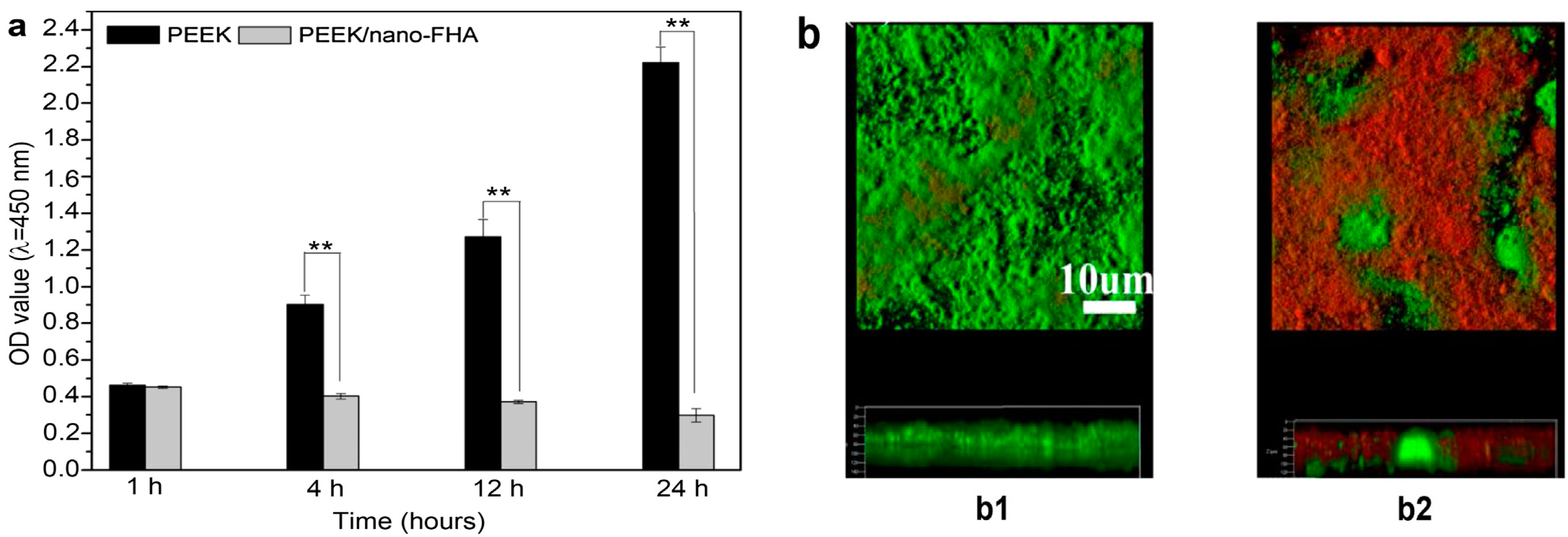
- Wang, L.; He, S.; Wu, X.; Liang, S.; Mu, Z.; Wei, J.; Deng, F.; Deng, Y.; Wei, S. Polyetheretherketone/nano-fluorohydroxyapatite composite with antimicrobial activity and osseointegration properties. Biomaterials 2014, 35, 6758–6775. [Google Scholar] [CrossRef]
- Kuśnieruk, S.; Wojnarowicz, J.; Chodara, A.; Chudoba, D.; Gierlotka, S.; Lojkowski, W. Influence of hydrothermal synthesis parameters on the properties of hydroxyapatite nanoparticles. Beilstein J. Nanotechnol. 2016, 7, 1586–1601. [Google Scholar] [CrossRef] [PubMed] [Green Version]
- Wang, K.; Zhou, C.; Hong, Y.; Zhang, X. A review of protein adsorption on bioceramics. Interf. Focus. 2012, 2, 259–277. [Google Scholar] [CrossRef] [PubMed]
- Wrobel, E.; Leszczynska, J.; Brzoska, E. The characteristics of human bone-derived cells (HBDCS) during osteogenesis in vitro. Cell Mol. Biol. Lett. 2016, 21, 26. [Google Scholar] [CrossRef] [PubMed] [Green Version]
- Blair, H.C.; Larrouture, Q.C.; Li, Y.; Lin, H.; Beer-Stoltz, D.; Liu, L.; Tuan, R.S.; Robinson, L.J.; Schlesinger, P.H.; Nelson, D.J. Osteoblast differentiation and bone matrix formation in vivo and in vitro. Tissue Eng. Part B Rev. 2017, 23, 268–280. [Google Scholar] [CrossRef] [PubMed] [Green Version]
- Zhao, H.; Li, M.; Liu, X.; Wei, J.; Ji, J.; Yang, S.; Hu, Z. Response of human osteoblast to n-HA/PEEK—Quantitative proteomic study of bio-effects of nano-hydroxyapatite composite. Sci. Rep. 2016, 6, 22832. [Google Scholar] [CrossRef] [Green Version]
- Sridhar, S.; Wilson Jr, T.G.; Palmer, K.L.; Valderrama, P.; Mathew, M.T.; Prasad, S.; Jacobs, M.; Grindi, I.M.; Rodrigues, D.C. In vitro Investigation of the effect of oral bacteria in the surface oxidation of dental implants. Clin. Implant Dent. Relat. Res. 2015, 17, e562–e575. [Google Scholar] [CrossRef]
- Ghensi, P.; Bettio, E.; Maniglio, D.; Bonomi, E.; Piccoli, F.; Gross, S.; Caciagli, P.; Segata, N.; Nollo, G.; Tessarolo, F. Dental implants with anti-biofilm properties: A pilot study for developing a new Sericin-based coating. Materials 2019, 12, 2429. [Google Scholar] [CrossRef] [Green Version]
- McGlynn, E.; Henry, M.O.; Mosnier, J.P. ZnO wide-bandgap semiconductor nanostructures: Growth, characterization and applications. In Oxford Handbook of Nanoscience and Technology; Narikar, A.V., Fu, Y.Y., Eds.; Oxford University Press: Oxford, UK, 2010; Volume 2. [Google Scholar] [CrossRef]
- Nosaka, Y.; Nosaka, A.Y. Generation and detection of reactive oxygen species in photocatalysis. Chem. Rev. 2017, 117, 11302–11336. [Google Scholar] [CrossRef]
- Jesline, A.; John, N.P.; Narayanan, P.M.; Vani, C.; Murugan, S. Antimicrobial activity of zinc and titanium dioxide nanoparticles against biofilm-producing methicillin-resistant Staphylococcus aureus. Appl. Nanosci. 2015, 5, 157–162. [Google Scholar] [CrossRef] [Green Version]
- Bogdan, J.; Zarzynska, J.; Plawinska-Czarnak, J. Comparison of infectious agents susceptibility to photocatalytic effects of nanosized titanium and zinc oxides: A practical approach. Nanoscale Res. Lett. 2015, 10, 309. [Google Scholar] [CrossRef] [Green Version]
- Prasanna, V.L.; Vijayaraghavan, R. Insight into the mechanism of antibacterial activity of ZnO: Surface defects mediated reactive oxygen species even in the dark. Langmuir 2015, 31, 9155–9162. [Google Scholar] [CrossRef] [PubMed]
- Sirelkhatim, A.; Mahmud, S.; Seeni, A.; Kaus, N.H.; Ann, L.C.; Bakhori, S.J.; Hasan, H.; Mohamad, D. Review on zinc oxide nanoparticles: Antibacterial activity and toxicity mechanism. Nanomicro Lett. 2015, 7, 219–242. [Google Scholar] [CrossRef] [PubMed] [Green Version]
- VanEpps, J.S.; Younger, J.G. Implantable device related infection. Shock 2016, 46, 597–608. [Google Scholar] [CrossRef] [PubMed] [Green Version]
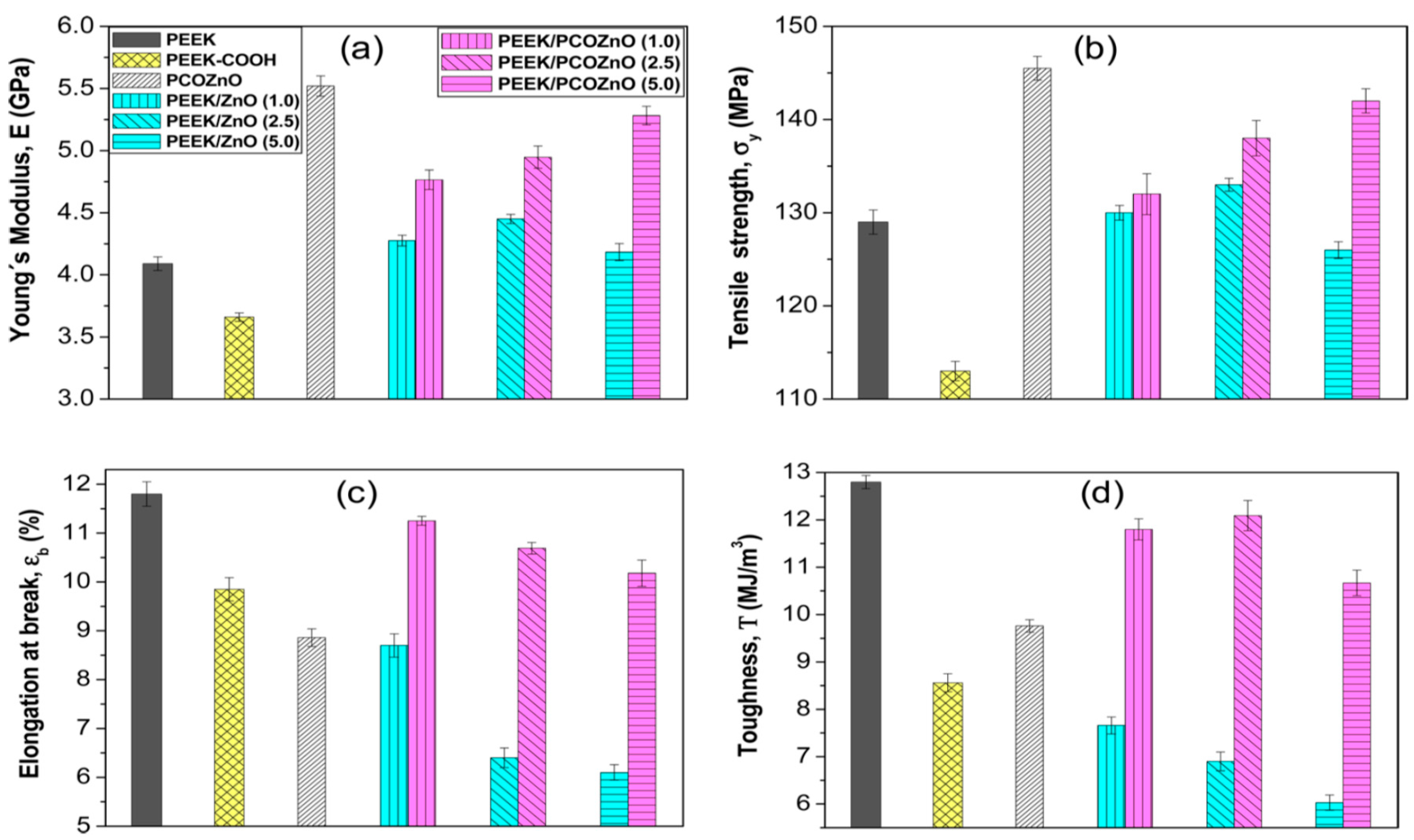
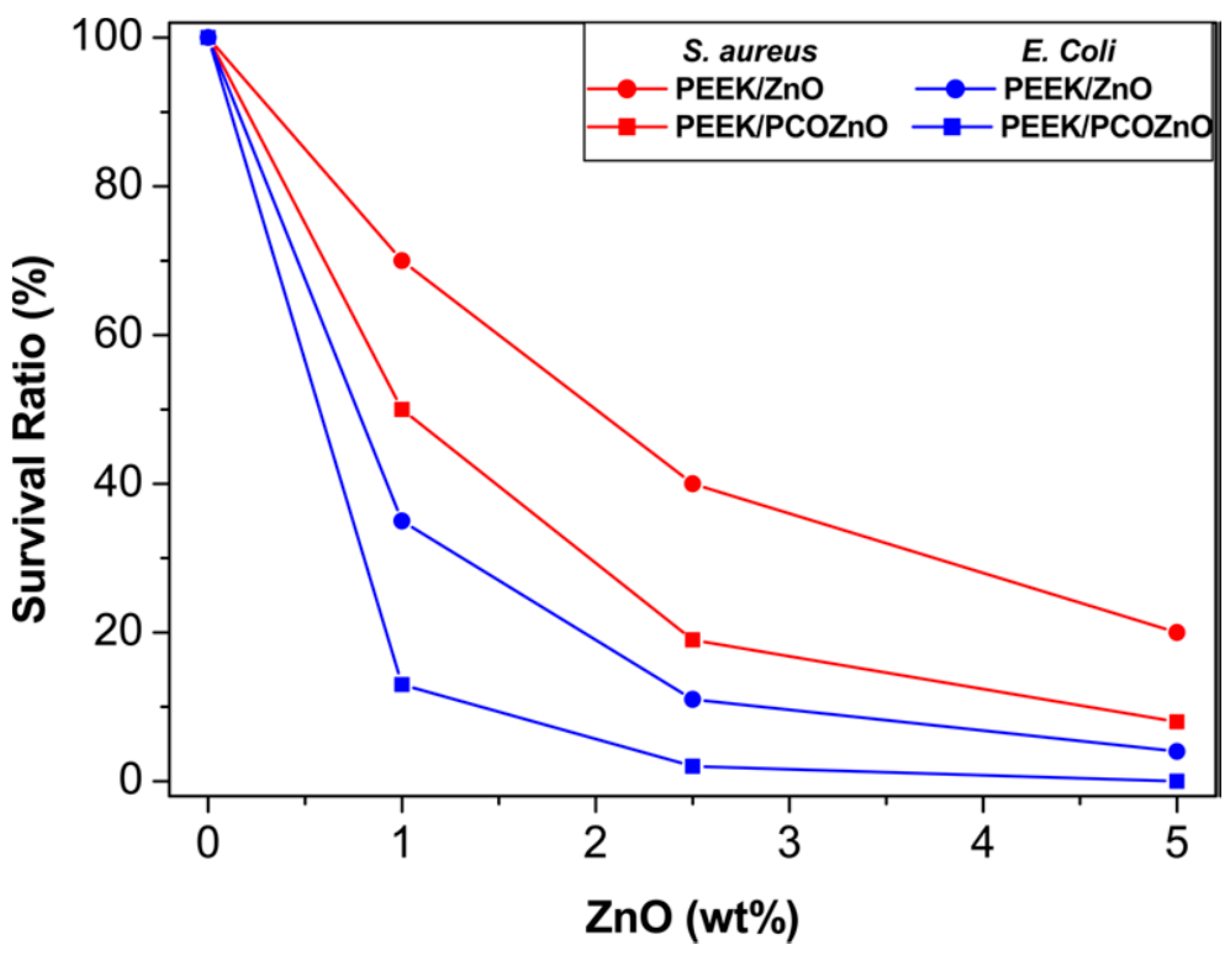
- Díez-Pascual, A.M.; Díez-Vicente, A.L. Development of nanocomposites reinforced with carboxylated poly (ether ether ketone) grafted to zinc oxide with superior antibacterial properties. ACS Appl. Mater. Interfaces 2014, 6, 3729–3741. [Google Scholar] [CrossRef] [Green Version]
- Arciola, C.R.; Campoccia, D.; Montanaro, L. Implant infections: Adhesion, biofilm formation and immune evasion. Nat. Rev. Microbiol. 2018, 16, 397–409. [Google Scholar] [CrossRef]
- Auer, G.K.; Weibel, D.B. Bacterial cell mechanics. Biochemistry 2017, 56, 3710–3724. [Google Scholar] [CrossRef]
- Díez-Pascual, A.M.; Xu, C.; Luque, R. Development and characterization of novel poly (ether ether ketone)/ZnO bionanocomposites. J. Mater. Chem. B 2014, 2, 3065–3078. [Google Scholar] [CrossRef] [Green Version]
- Yu, M.F.; Files, B.S.; Arepalli, S.; Ruoff, R.S. Tensile loading of ropes of single wall carbon nanotubes and their mechanical properties. Phys. Rev. Lett. 2000, 84, 5552. [Google Scholar] [CrossRef] [Green Version]
- Lee, C.; Wei, X.D.; Kysar, J.W.; Hone, J. Measurement of the elastic properties and intrinsic strength of monolayer graphene. Science 2008, 321, 385–388. [Google Scholar] [CrossRef]
- Tjong, S.C. Polymer Composites with Carbonaceous Nanofillers: Properties and Applications; Wiley-VCH: Weinheim, Germany, 2012; ISBN 9783527410804. [Google Scholar]
- Díez-Pascual, A.M. Carbon-based polymer nanocomposites for high-performance applications. Polymers 2020, 12, 872. [Google Scholar] [CrossRef] [Green Version]
- Wu, S.; Peng, S.; Wang, C.H. Multifunctional polymer nanocomposites reinforced by aligned carbon nanomaterials. Polymers 2018, 10, 542. [Google Scholar] [CrossRef] [PubMed] [Green Version]
- Demczyk, B.G.; Wang, Y.M.; Cumings, J.; Hetman, M.; Han, W.; Zettl, A.; Ritchie, R.O. Direct mechanical measurement of the tensile strength and elastic modulus of multiwalled carbon nanotubes. Mater. Sci. Eng. A 2002, 334, 173–178. [Google Scholar] [CrossRef]
- Kim, Y.A.; Hayashi, T.; Naokawa, S.; Yanagisawa, T.; Endo, M. Comparative study of herringbone and stacked-cup carbon nanofibers. Carbon 2005, 43, 3005–3008. [Google Scholar] [CrossRef] [Green Version]
- Moyseowicz, A.; Sliwak, A.; Gryglewicz, G. Influence of structural and textural parameters of carbon nanofibers on their capacitive behavior. J. Mater. Sci. 2016, 51, 3431–3439. [Google Scholar] [CrossRef] [Green Version]
- Pei, B.; Wang, W.; Dunne, N.; Li, X. Applications of carbon nanotubes in bone tissue regeneration and engineering: Superiority, concerns, current advancements, and prospects. Nanomaterials 2019, 9, 1501. [Google Scholar] [CrossRef] [Green Version]
- Gorain, B.; Choudhury, H.; Pandey, M.; Kesharwani, P.; Abeer, M.M.; Tekade, R.K.; Hussain, Z. Carbon nanotube scaffolds as emerging nanoplatform for myocardial tissue regeneration: A review of recent developments and therapeutic implications. Biomed. Pharmacother. 2018, 104, 496–508. [Google Scholar] [CrossRef]
- Gonçalves, C.; Gonçalves, I.C.; Magalhães, F.D.; Pinto, A.M. Poly (lactic acid) composites containing carbon-based nanomaterials: A review. Polymers 2017, 9, 269. [Google Scholar] [CrossRef] [Green Version]
- Suk, J.W.; Piner, R.D.; An, J.; Ruoff, R.S. Mechanical properties of monolayer graphene oxide. ACS Nano 2010, 4, 6557–6564. [Google Scholar] [CrossRef]
- Dideikin, A.T.; Vul, A.Y. Graphene oxide and derivatives: The place in graphene family. Front. Phys. 2019, 6, 149. [Google Scholar] [CrossRef]
- Díez-Pascual, A.M.; Díez-Vicente, A.L. Multifunctional poly (glycolic acid-co-propylene fumarate) electrospun fibers reinforced with graphene oxide and hydroxyapatite nanorods. J. Mater. Chem. B 2017, 5, 4084–4096. [Google Scholar] [CrossRef]
- He, M.; Chen, X.; Guo, Z.; Qiu, X.; Yang, Y.; Su, C.; Jiang, N.; Li, Y.; Sun, D.; Zhang, L. Super tough graphene oxide reinforced polyetheretherketone for potential hard tissue repair applications. Compos. Sci. Technol. 2019, 174, 194–201. [Google Scholar] [CrossRef] [Green Version]
- Deng, F.; Ogasawara, T.; Takeda, N. Tensile properties at different temperature and observation of micro deformation of carbon nanotubes–poly (ether ether ketone) composites. Compos. Sci. Technol. 2007, 67, 2959–2964. [Google Scholar] [CrossRef]
- Falvo, M.R.; Clary, G.J.; Taylor, R.M.; Chi, V.; Brooks, F.P., Jr.; Washburn, S.; Superfine, R. Bending and buckling of carbon nanotubes under large strain. Nature 1997, 389, 582–584. [Google Scholar] [CrossRef] [PubMed]
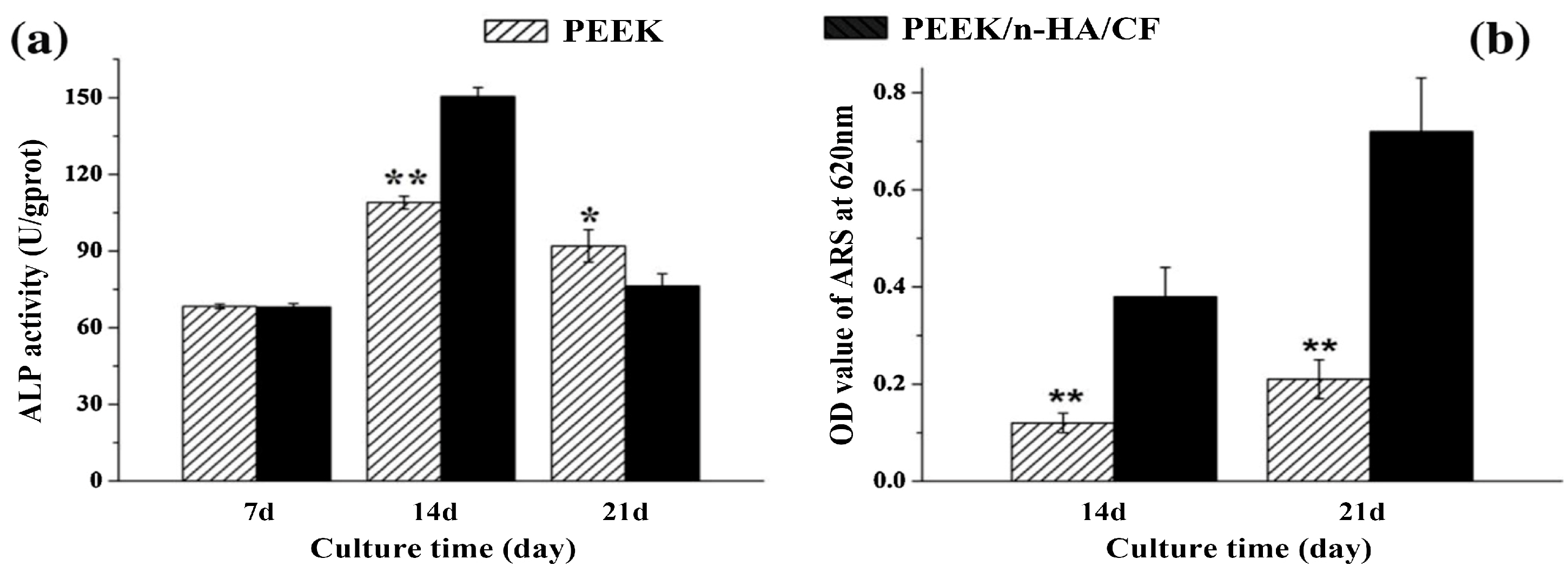
- Deng, Y.; Zhou, P.; Liu, X.; Wang, L.; Xiong, X.; Tang, Z.; Wei, J.; Wei, S. Preparation, characterization, cellular response and in vivo osseointegration of polyetheretherketone/nano-hydroxyapatite/carbon fiber ternary biocomposite. Colloids Surf. B Biointerfaces 2015, 136, 64–73. [Google Scholar] [CrossRef] [PubMed]
- Khazi-Syed, A.; Hasan, M.T.; Campbell, E.; Gonzalez-Rodriguez, R.; Naumov, A.V. Single-walled carbon nanotube-assisted antibiotic delivery and imaging in S. epidermidis strains addressing antibiotic resistance. Nanomaterials 2019, 9, 1685. [Google Scholar] [CrossRef] [PubMed] [Green Version]
- Bishop, L.; Cena, L.; Orandle, M.; Yanamala, N.; Dahm, M.M.; Birch, M.E.; Evans, D.E.; Kodali, V.K.; Eye, T.; Battelli, L.; et al. In vivo toxicity assessment of occupational components of the carbon nanotube life cycle to provide context to potential health effects. ACS Nano 2017, 11, 8849–8863. [Google Scholar] [CrossRef] [PubMed]
- Hamilton, R.F., Jr.; Wu, Z.; Mitra, S.; Holian, A. The effects of varying degree of MWCNT carboxylation on bioactivity in various in vivo and in vitro exposure models. Int. J. Mol. Sci. 2018, 19, 354. [Google Scholar] [CrossRef] [Green Version]
- Kavosi, A.; Hosseini Ghale Noei, S.; Madani, S.; Madani, S.; Khalighfard, S.; Khodayari, S.; Khodayari, H.; Mirzaei, M.; Kalhori, M.R.; Alizadeh, A.M.; et al. The toxicity and therapeutic effects of single-and multi-wall carbon nanotubes on mice breast cancer. Sci. Rep. 2018, 8, 8375. [Google Scholar] [CrossRef] [Green Version]
- Jacobsen, N.R.; Moller, P.; Clausen, P.A.; Saber, A.T.; Micheletti, C.; Jensen, K.A.; Wallin, H.; Vogel, U. Biodistribution of carbon nanotubes in animal models. Basic Clin. Pharmacol. Toxicol. 2017, 121 (Suppl. 3), 30–43. [Google Scholar] [CrossRef] [Green Version]
- Perez-Puyana, V.; Jiménez-Rosado, M.; Romero, A.; Guerrero, A. Polymer-based scaffolds for soft-tissue engineering. Polymers 2020, 12, 1566. [Google Scholar] [CrossRef]
- Chocholata, P.; Kulda, V.; Babuska, V. Fabrication of scaffolds for bone-tissue regeneration. Materials 2019, 12, 568. [Google Scholar] [CrossRef] [PubMed] [Green Version]
- Kołbuk, D.; Heljak, M.; Choińska, E.; Urbanek, O. Novel 3D hybrid nanofiber scaffolds for bone regeneration. Polymers 2020, 12, 544. [Google Scholar] [CrossRef] [PubMed] [Green Version]
- Henkel, J.; Woodruff, M.; Epari, D.; Steck, R.; Glatt, V.; Dickinson, I.C.; Choong, P.F.; Schuetz, M.A.; Hutmacher, D.W. Bone regeneration based on tissue engineering conceptions—A 21st century perspective. Bone Res. 2013, 1, 216–248. [Google Scholar] [CrossRef] [PubMed] [Green Version]
- Abalymov, A.; Parakhonskiy, B.; Skirtach, A.G. Polymer- and hybrid-based biomaterials for interstitial, connective, vascular, nerve, visceral and musculoskeletal tissue engineering. Polymers 2020, 12, 620. [Google Scholar] [CrossRef] [PubMed] [Green Version]
- Santos-Rosales, V.; Iglesias-Mejuto, A.; García-González, C.A. Solvent-free approaches for the processing of scaffolds in regenerative medicine. Polymers 2020, 12, 533. [Google Scholar] [CrossRef] [Green Version]
- Donnaloja, F.; Jacchetti, E.; Soncini, M.; Raimondi, M.T. Natural and synthetic polymers for bone scaffolds optimization. Polymers 2020, 12, 905. [Google Scholar] [CrossRef] [Green Version]
- Ozbolat, I.T.; Hospodiuk, M. Current advances and future perspectives in extrusion-based bioprinting. Biomaterials 2016, 76, 321–343. [Google Scholar] [CrossRef] [Green Version]
- Huang, B.; Caetano, G.; Vyas, C.; Blaker, J.J.; Diver, C.; Bártolo, P. Polymer-ceramic composite scaffolds: The effect of hydroxyapatite and β-tricalcium phosphate. Materials 2018, 11, 129. [Google Scholar] [CrossRef] [Green Version]
- Vaezi, M.; Yang, S. Extrusion-based additive manufacturing of PEEK for biomedical applications. Virtual Phys. Prototy. 2015, 10, 123–135. [Google Scholar] [CrossRef]
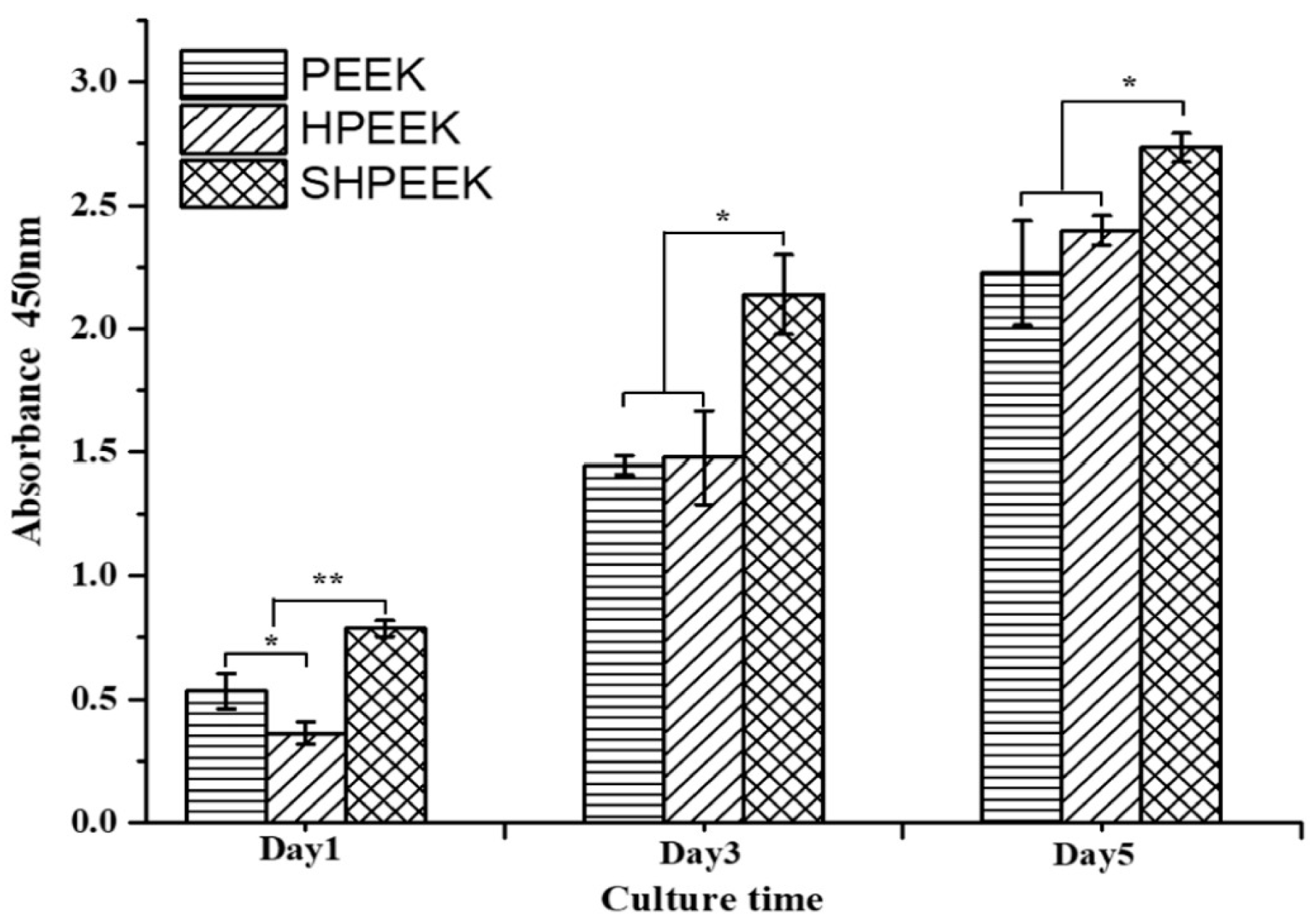
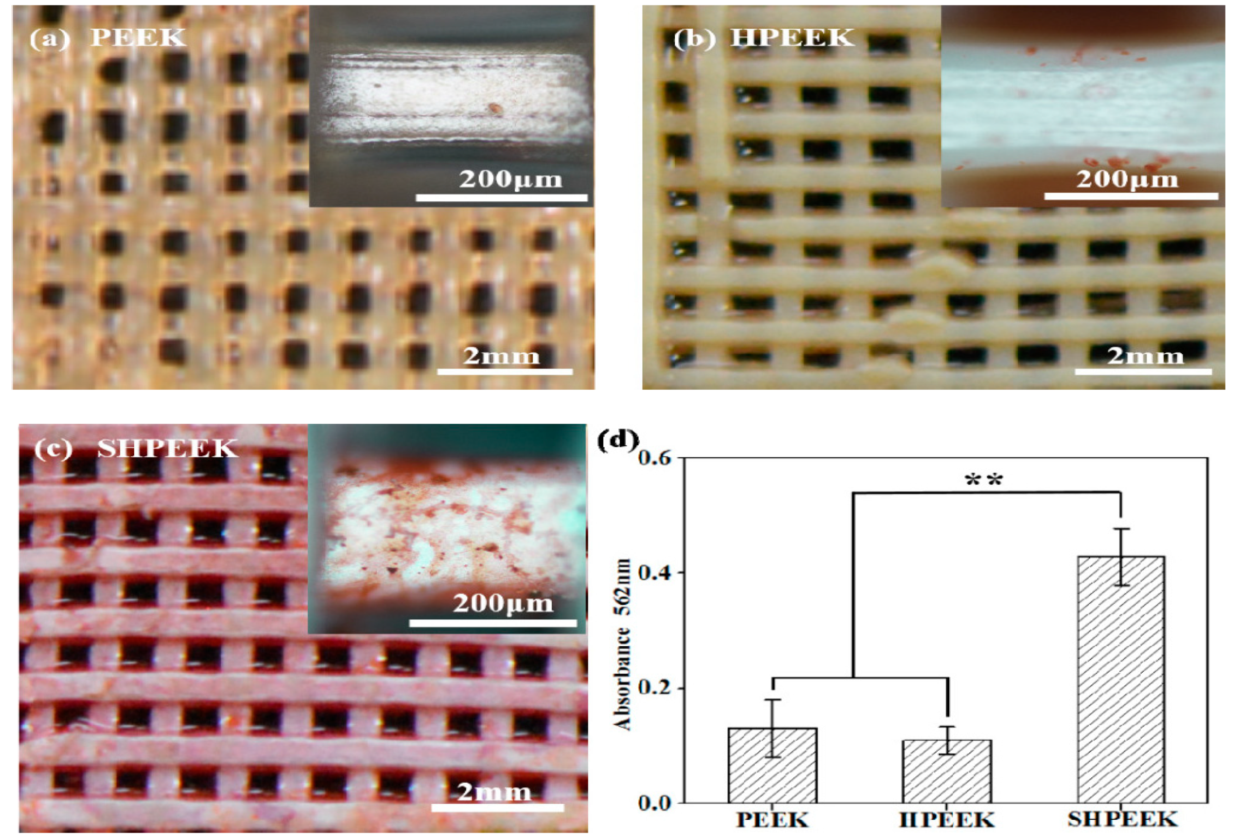
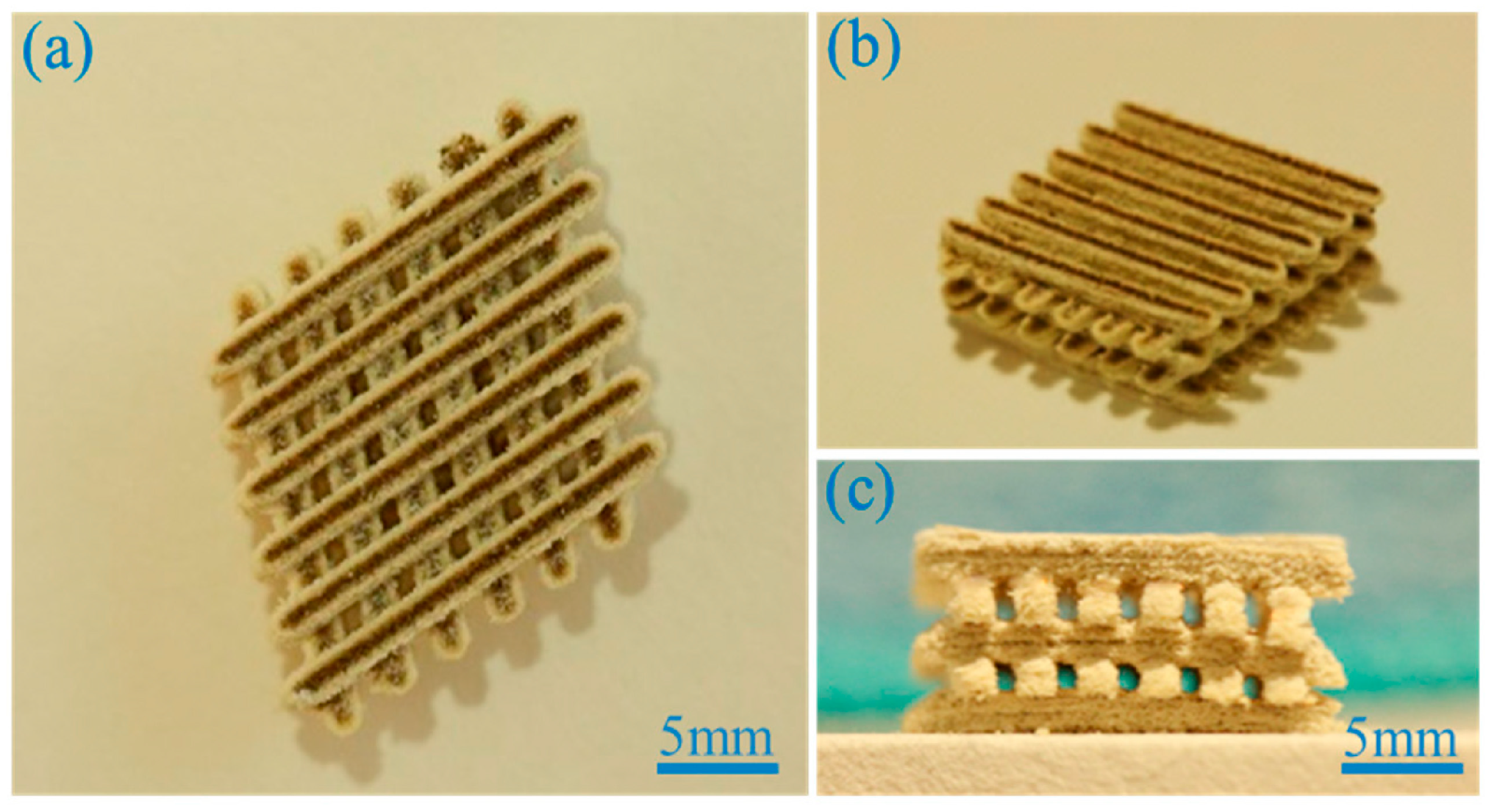
- Su, Y.; He, J.; Jiang, N.; Zhang, H.; Wang, L.; Liu, X.; Li, D.; Yin, Z. Additively-manufactured poly-ether-ether-ketone (PEEK) lattice scaffolds with uniform microporous architectures for enhanced cellular response and soft tissue adhesion. Mater. Des. 2020, 191, 108671. [Google Scholar] [CrossRef]
- Feng, X.; Yu, H.; Liu, H.; Yu, X.; Feng, Z.; Bai, S.; Zhao, Y. Three-dimensionally-printed polyether-ether-ketone implant with a cross-linked structure and acid-etched microporous surface promotes integration with soft tissue. Int. J. Mol. Sci. 2019, 20, 3811. [Google Scholar] [CrossRef] [PubMed] [Green Version]
- Datta, P.; Ayan, B.; Ozbolat, I.T. Bioprinting for vascular and vascularized tissue biofabrication. Acta Biomater. 2017, 51, 1–20. [Google Scholar] [CrossRef] [PubMed] [Green Version]
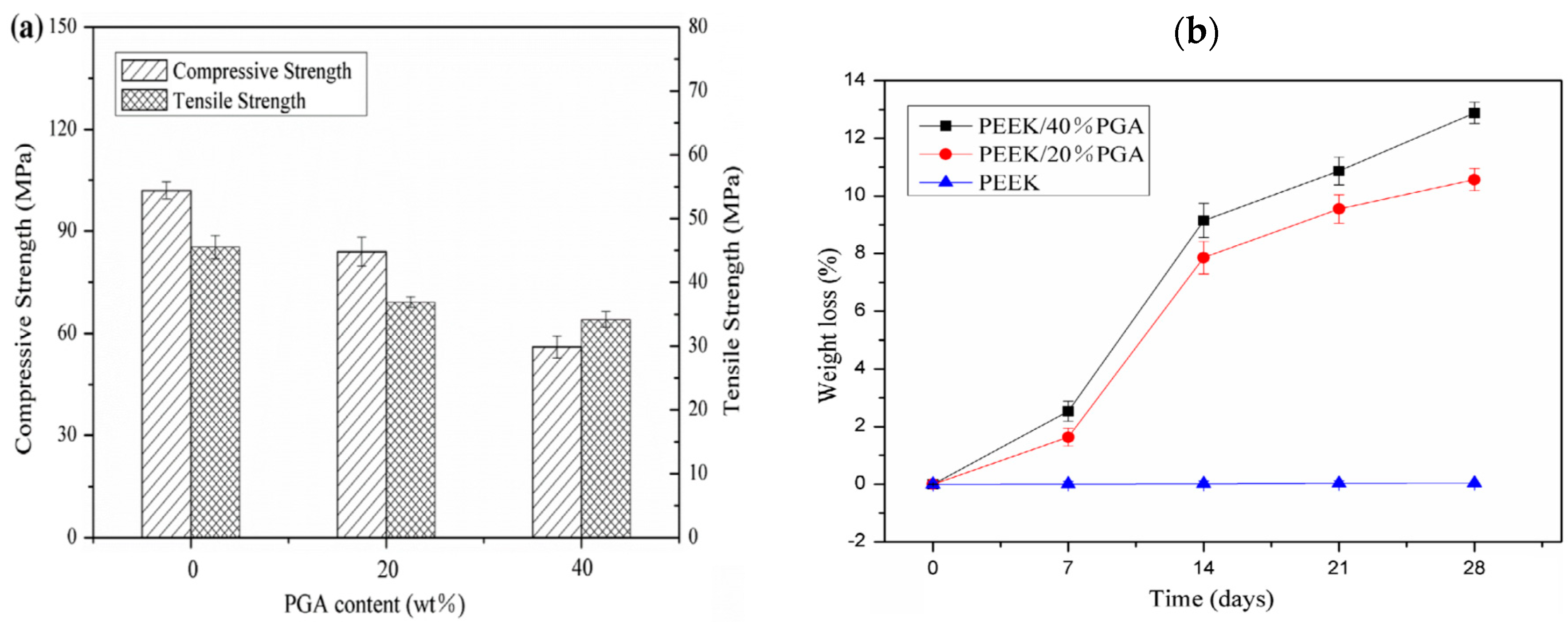
- Shuai, C.; Wu, P.; Zhong, Y.; Feng, P.; Gao, C.; Huang, W.; Zhou, Z.; Chen, L.; Shuai, C. Polyetheretherketone/poly (glycolic acid) blend scaffolds with biodegradable properties. J. Biomater. Sci. Polym. Ed. 2016, 27, 1434–1446. [Google Scholar] [CrossRef] [PubMed]
- Shuai, C.; Shuai, C.; Wu, P.; Yuan, F.; Feng, P.; Yang, Y.; Guo, W.; Fan, X.; Su, T.; Peng, S.; et al. Characterization and bioactivity evaluation of (polyetheretherketone/polyglycolicacid)-hydroyapatite scaffolds for tissue regeneration. Materials 2016, 9, 934. [Google Scholar] [CrossRef] [PubMed]
- Feng, P.; Jia, J.; Peng, S.; Yang, W.; Bin, S.; Shuai, C. Graphene oxide-driven interfacial coupling in laser 3D printed PEEK/PVA scaffolds for bone regeneration. Virtual Phys. Prototy. 2020, 15, 211–226. [Google Scholar] [CrossRef]
- Woodard, L.N.; Grunlan, M.A. Hydrolytic degradation and erosion of polyester biomaterials. ACS Macro Lett. 2018, 7, 976–982. [Google Scholar] [CrossRef] [Green Version]
- Khiste, S.V.; Ranganath, V.; Nichani, A.S. Evaluation of tensile strength of surgical synthetic absorbable suture materials: An in vitro study. J. Periodontal Implant Sci. 2013, 43, 130–135. [Google Scholar] [CrossRef] [Green Version]
- Hench, L.L.; Wilson, J. An Introduction to Bioceramics; World Scientific: Singapore, 1993; Chapter 1; pp. 1–26. [Google Scholar]
- Novitskaya, E.; Chen, P.Y.; Hamed, E.; Li, J.; Lubarda, V.A.; Jasiuk, I.; McKittrick, J. Recent advances on the measurement and calculation of the elastic moduli of cortical and trabecular bone: A review. Theoret. Appl. Mech. 2011, 38, 209–297. [Google Scholar] [CrossRef]
- Arnold, A.M.; Holt, B.D.; Daneshmandi, L.; Laurencin, C.T.; Sydlik, S.A. Phosphate graphene as an intrinsically osteoinductive scaffold for stem cell-driven bone regeneration. Proc. Nat. Acad. Sci. USA 2019, 116, 4855–4860. [Google Scholar] [CrossRef] [Green Version]
- Garcia-Alegria, E.; Iliut, M.; Stefanska, M.; Silva, C.; Heeg, S.; Kimber, S.J.; Kouskoff, V.; Lacaud, G.; Vijayaraghavan, A.; Batta, K. Graphene oxide promotes embryonic stem cell differentiation to haematopoietic lineage. Sci. Rep. 2016, 6, 25917. [Google Scholar] [CrossRef] [Green Version]
- Thavornyutikarn, B.; Chantarapanich, N.; Sitthiseripratip, K.; Thouas, G.A.; Chen, Q. Bone tissue engineering scaffolding: Computer-aided scaffolding techniques. Prog. Biomater. 2014, 3, 61–102. [Google Scholar] [CrossRef] [PubMed] [Green Version]
- Thiagarajan, L.; Abu-Awwad, H.A.; Dixon, J.E. Osteogenic programming of human mesenchymal stem cells with highly efficient intracellular delivery of RUNX2. Stem Cells Transl. Med. 2017, 6, 2146–2159. [Google Scholar] [CrossRef] [PubMed]
- McGovern, J.A.; Griffin, M.; Hutmacher, D.W. Animal models for bone tissue engineering and modelling disease. Dis. Model Mech. 2018, 11. [Google Scholar] [CrossRef] [PubMed] [Green Version]
- Saito, N.; Hanio, H.; Usui, Y.; Aoki, K.; Hara, K.; Takanashi, S.; Shimizu, M.; Narita, N.; Okamoto, M.; Kobayashi, S.; et al. Safe clinical use of carbon nanotubes as innovative biomaterials. Chem. Rev. 2014, 114, 6040–6079. [Google Scholar] [CrossRef]
- Prased, J.; Drbohlavova, J.; Chomoucka, J.; Hubalek, J.; Jasek, O.; Adam, V.; Kizek, R. Methods for carbon nanotubes synthesis—Review. J. Mater. Chem. 2011, 21, 15872–15884. [Google Scholar] [CrossRef]
- Manke, A.; Wang, L.; Rojanasakul, Y. Pulmonary toxicity and fibrogenic response of carbon nanotubes. Toxicol. Mech. Methods 2013, 23, 196–206. [Google Scholar] [CrossRef] [Green Version]
- Kasliwal, M.K.; Tan, L.A.; Traynelis, V.C. Infection with spinal instrumentation: Review of pathogenesis, diagnosis, prevention, and management. Surg. Neurol. Int. 2013, 4, S392–S403. [Google Scholar] [CrossRef]
- Jonsson, E.O.; Johannesdottir, H.; Robertsson, O.; Mogensen, B. Bacterial contamination of the wound during primary total hip and knee replacement. Median 13 years of follow-up of 90 replacements. Acta Orthop. 2014, 85, 159–164. [Google Scholar] [CrossRef] [Green Version]
- Staroń, A.; Długosz, O.; Pulit-Prociak, J.; Banach, M. Analysis of the exposure of organisms to the action of nanomaterials. Materials 2020, 13, 349. [Google Scholar] [CrossRef] [Green Version]


| Sample | Elastic Modulus, GPa | Tensile Strength, MPa | Elongation at Break,% | Reference |
|---|---|---|---|---|
| Pure PEEK | 3.90 ± 0.2 | 93 ± 1 | 66 ± 7 | [150] |
| Pure PEEK | 3.87 ± 0.10 | 80.06±0.49 | 67.10 ± 13.40 | [62,63] |
| Pure PEEK | 3.79 ± 0.27 | 95.21 ± 1.86 | N.A. | [45] |
| Pure PEEK | 2.20 ± 0.17 | 84.0±1.9 | N.A. | [87] |
| PEEK/10 vol% (20.79 wt%) mHA | 4.33 ± 0.94 | 64.71±1.46 | 19.23 ± 2.74 | [131] |
| PEEK/20 vol% (37.64 wt%) mHA | 4.78 ± 1.38 | 58.59 ±1.91 | 4.26 ± 0.72 | [131] |
| PEEK/30 vol% (50.86 wt%) mHA | 8.17 ± 1.09 | 49.15 ±2.08 | 1.96 ± 0.08 | [131] |
| PEEK/40vol% (61.68wt%) mHA | 15.37 ± 3.30 | 43.76 ±5.26 | 0.98 ± 0.52 | [131] |
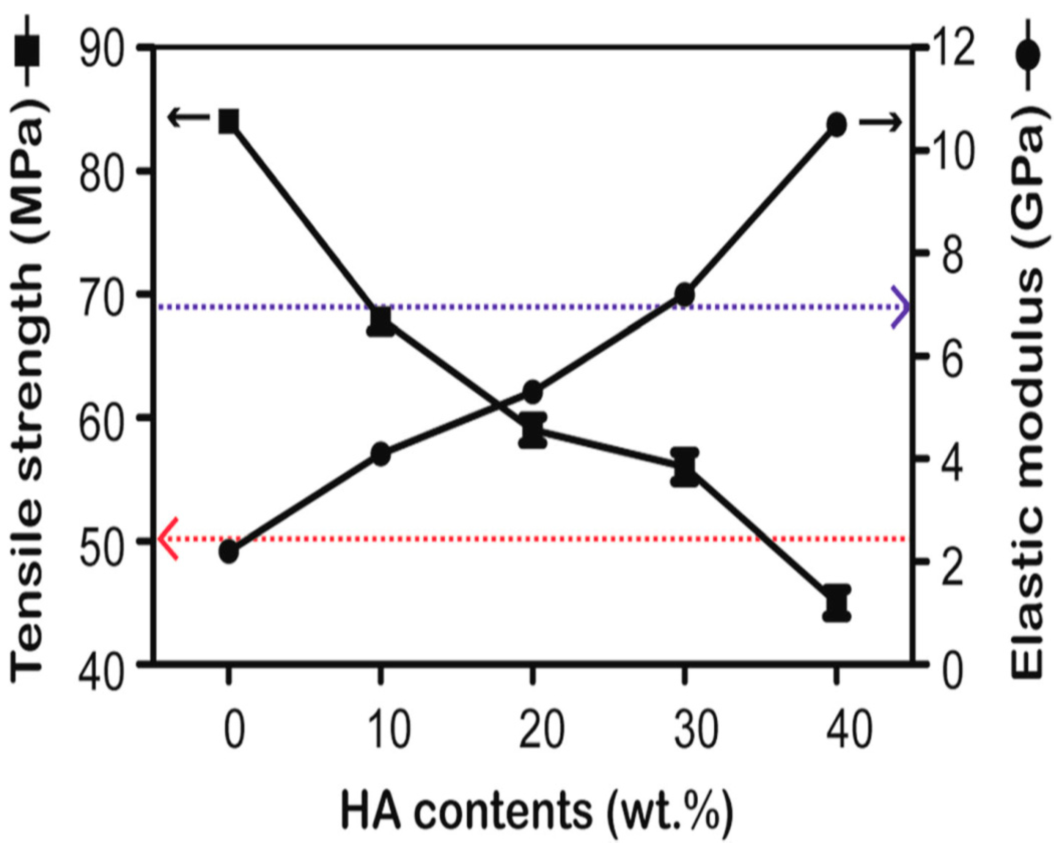
| PEEK/30 wt% mHA | 7.2 | 57 | N.A. | [135] |
| PEEK/40 wt% mHA | 10.4 | 45 ± 2.5 | N.A. | [135] |
| Endolign® (unidirectional) | 150 | 2000 | N.A. | [146] |
| Endolign® (multidirectional) | 70 | 900 | N.A. | [146] |
| PEEK/5 wt% SCF | 7.37 ± 1.22 | 101.41 ± 4.23 | N.A. | [45] |
| PEEK/30 wt% SCF (PAN) | 24 | 214 | 2.0 | [42] |
| PEEK/30 wt% SCF (PAN) | 18.5 ± 2.3 | 192 ± 17 | 1.9 ± 0.2 | [150] |
| PEEK/30 wt% SCF (Pitch) | 12.5 ± 1.3 | 145 ± 9 | 2.2 ± 0.2 | [150] |
| Human cortical bone | 7–30 | 50–100 | 1–3 | [9] |
| Sample | Elastic Modulus, GPa | Tensile Strength, MPa | Elongation at Break, % | Ref. |
|---|---|---|---|---|
| PEEK-based Hybrid Composites: | ||||
| PEEK/30 wt% nHA-2 wt% CNF | 6.54 ± 0.29 | 71.67 ± 5.25 | 2.83 ± 0.66 | [62] |
| PEEK/30 wt% nHA-1.5 wt% MWNT | 6.83 ± 0.20 | 70.99 ± 7.51 | 2.32 ± 1.15 | [63] |
| PEEK/30 wt% nHA-3.0 wt% MWNT | 7.13 ± 0.12 | 64.48± 8.51 | 1.74 ± 0.58 | [63] |
| PEEK/25 wt% nHA-20 wt% SCF | 16.5 ± 0.7 | 138 | N.A. | [200] |
| PEEK-based Nanocomposites: | ||||
| PEEK/ 10wt% nHA | 4.34 ± 0.08 | 80.55 ± 0.15 | 31.4 ± 5.18 | [62] |
| PEEK/20 wt% nHA | 4.92 ± 0.06 | 81.23 ± 0.55 | 7.62 ± 0.27 | [62] |
| PEEK/30 wt% nHA | 6.20 ± 0.13 | 70.56 ± 3.22 | 2.71 ± 0.34 | [62] |
| PEEK/40 wt% nHA | 7.85 ± 0.11 | 44.51 ± 7.53 | 0.69 ± 0.21 | [62] |
| PEEK/20 wt% nHA | 3.40 ± 0.20 | 81.0 ± 2.4 | N.A. | [87] |
| PEEK/40 wt% nHA | 4.60 ± 0.12 | 75.0 ± 2.7 | N.A. | [87] |
| PEEK/1.5 wt% MWNT | 4.21 ± 0.11 | 83.38 ± 0.78 | 57.25 ± 13.20 | [63] |
| PEEK/3.0 wt% MWNT | 4.25 ± 0.85 | 82.08 ± 3.68 | 56.48 ± 24.90 | [63] |
| PEEK/6.5 wt% MWNT | 5.32 | 102.15 | 12.49 | [198] |
| PEEK/12 wt% MWNT | 6.35 | 107.14 | 8.28 | [198] |
| PEEK/15 wt% MWNT | 7.55 | 110.90 | 6.28 | [198] |
| Scaffold | Strengths | Weaknesses |
|---|---|---|
| FFF-printed PEEK | Ease of fabrication. No additional processing steps are needed. | The printed scaffolds are bioinert and nondegradable. No micropores formed on the filaments of printed scaffolds for osteoblastic adhesion. The macro-pores formed between the filaments created by printing are far too large for bone cell adhesion |
| SHPEEK | Sulfonation of FFF-printed PEEK creates micropores on the filaments for bone cell adhesion | Sulfuric acid residuals can damage bone cells and reduce their viability greatly. After sulfonation, the scaffolds must be rinsed in water several times to remove the residuals until they are contamination-free. So, it is a tedious process. |
| SLS-printed PEEK-PGA | Degradable scaffolds due to the dissolution of PGA. SLS process creates rough surface needed for bone cell adhesion | High-temperature laser beam used for sintering polymer powders would degrade their properties. Raw polymer powders trap inside the fine voids of scaffolds due to printing are difficult to remove and may induce inflammation [228]. |
| SLS-printed PEEK-PGA/nHA | nHA and rough surface finish are beneficial for bone cell adhesion. nHA neutralizes autocatalytic effect of acidic PGA byproduct, thus reducing inflammation of wounds | As above |
| SLS-printed PEEK-PGA/GO | GO sheets with high stiffness and strength increase the compressive strength/stiffness of resulting nanocomposite scaffolds. GO promotes bone cell adhesion and growth | GO sheets must be firmly attached in the matrix of composite scaffold. Otherwise, stand-alone or delaminated GO may induce cytotoxicity to human cells [76] |
| Scaffold | Compressive Strength, MPa | Compressive Modulus, GPa | In Vitro Properties | In Vivo Animal Model | Ref. |
|---|---|---|---|---|---|
| SHPEEK | N. A. | N. A. | MC3T3-E1 cells adhere & grow on the micropores created by sulfonation. Mineralization of ECM by bone cells | N. A. | [216] |
| PEEK-20% PGA | 82.5 | N. A. | MG63 cells adhere on rough surface of scaffold | N. A. | [219] |
| PEEK-40% PGA | 52.5 | N. A. | MG63 cells adhere on rough surface of scaffold | N. A. | [219] |
| PEEK-20% PGA/10% nHA | 92.5 | 3.31 | Adding 10% nHA to PEEK-20%PGA increases cell viability and ALP activity of MG63 cells. | N. A. | [220] |
| PEEK-PVA | 10.12 | 1.22 | PVA improves wettability of PEEK by reducing water contact angle to 85.52°. | N. A. | [221] |
| PEEK-PVA/1%GO | 20.13 | 1.82 | Adding 1% GO to PEEK-PVA promotes the adhesion, growth and differentiation of MG63 cells. GO facilitates the dissolution of PVA phase in PBS solution, & further reduces water contact angle to 78.16°. | GO sheets enhance new bone formation in rabbits | [221] |
| Cancellous bone | 2–14 | 0.44 ± 0.27 | N. A. | N. A. | [224,225] |
Publisher’s Note: MDPI stays neutral with regard to jurisdictional claims in published maps and institutional affiliations. |
© 2020 by the authors. Licensee MDPI, Basel, Switzerland. This article is an open access article distributed under the terms and conditions of the Creative Commons Attribution (CC BY) license (http://creativecommons.org/licenses/by/4.0/).
Share and Cite
Liao, C.; Li, Y.; Tjong, S.C. Polyetheretherketone and Its Composites for Bone Replacement and Regeneration. Polymers 2020, 12, 2858. https://doi.org/10.3390/polym12122858
Liao C, Li Y, Tjong SC. Polyetheretherketone and Its Composites for Bone Replacement and Regeneration. Polymers. 2020; 12(12):2858. https://doi.org/10.3390/polym12122858
Chicago/Turabian StyleLiao, Chengzhu, Yuchao Li, and Sie Chin Tjong. 2020. "Polyetheretherketone and Its Composites for Bone Replacement and Regeneration" Polymers 12, no. 12: 2858. https://doi.org/10.3390/polym12122858