Helicoidally Arranged Polyacrylonitrile Fiber-Reinforced Strong and Impact-Resistant Thin Polyvinyl Alcohol Film Enabled by Electrospinning-Based Additive Manufacturing

 , , , and
Abstract
:
1. Introduction
2. Material and Methods
2.1. Materials
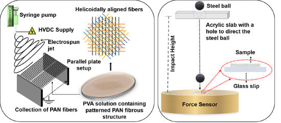
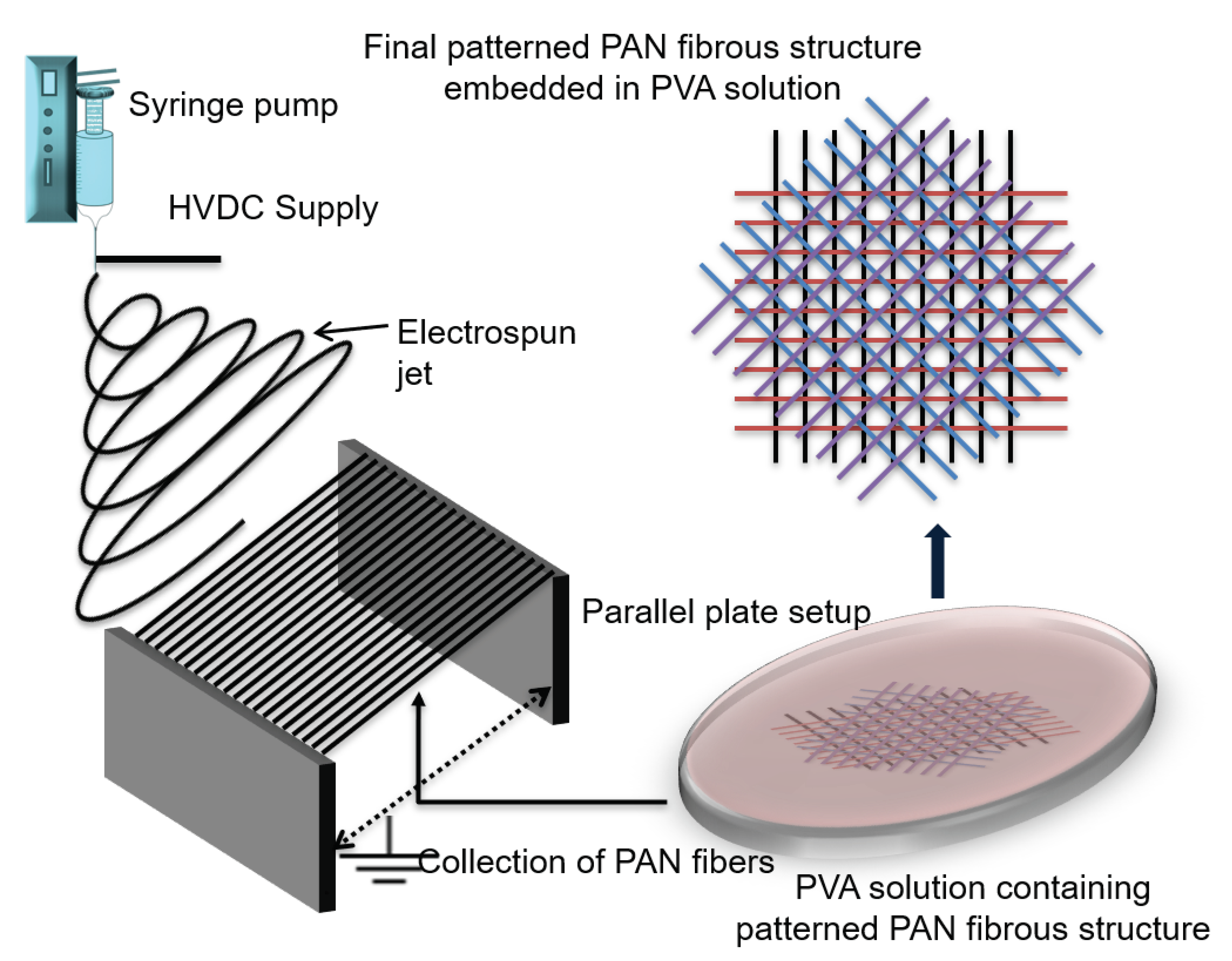
2.2. Methods
2.3. Characterization
3. Results and Discussion
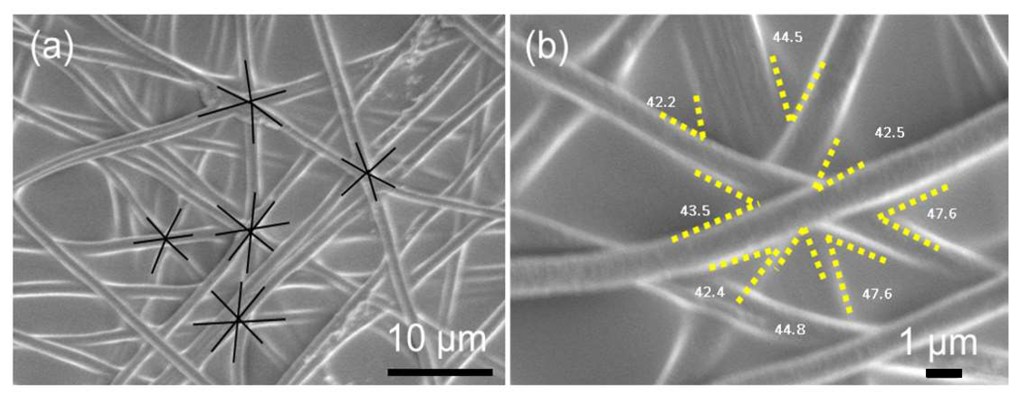
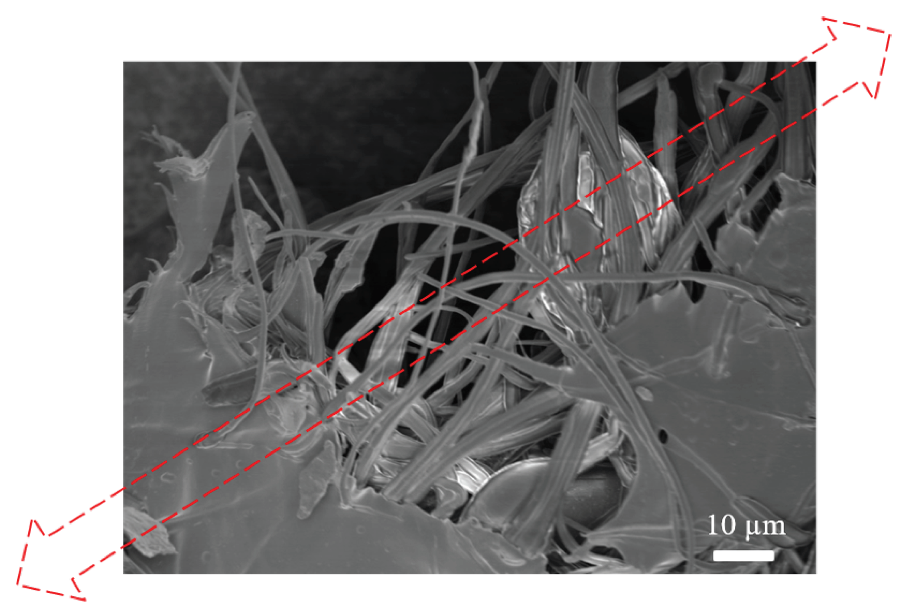
3.1. Physical Characterization of PVA SPTF
3.2. Chemical and Thermal Properties of PVA SPTF
3.2.1. Fourier-Transform Infrared Spectroscopy (FTIR)
3.2.2. Thermogravimetric Analysis (TGA)
3.2.3. Differential Scanning Calorimetry (DSC)
3.3. Mechanical Properties of PVA SPTF
3.3.1. Tensile Properties
3.3.2. Impact Resistance
4. Conclusions
Author Contributions
Funding
Acknowledgments
Conflicts of Interest
Abbreviations
| pp-FFES | Parallel plate far field electrospinning |
| TF | Thin films |
| SPTF | Strong polymer thin films |
| PAN | Polyacrylonitrile |
| PVA | polyvinyl alcohol |
| PVA SPTF-RO | PVA strong polymer thin films with randomly oriented PAN fibers |
| PVA SPTF-HA | PVA strong polymer thin films with helicoidally arranged PAN fibers |
Appendix A


| Sample | Ultimate Specific Tensile Strength | Strain | Specific Toughness | Density |
|---|---|---|---|---|
| (MPa·cm3·g−1) | (%) | (J·g−1) | (g·cm−3) | |
| PVA TF | 2.2 ± 0.2 | 114 ± 3 | 2.2 ± 0.3 | 1.1 |
| PVA SPTF-RO | 3.3 ± 0.4 | 61.4 ± 6 | 1.5 ± 0.4 | 1 |
| PVA SPTF-HA | 5 ± 0.3 | 64.4 ± 14 | 2.5 ± 0.4 | 0.7 |
| Sample | Impact Height at Which | Specific Impact Energy |
|---|---|---|
| Glass Beneath Sample Breaks | ||
| (cm) | (mJ·cm3·g−1) | |
| Coverslip | 20 ± 2 | - |
| PVA TF | 80 ± 5 | 3.4 ± 0.3 |
| PVA SPTF-RO | 84 ± 4 | 4.2 ± 0.5 |
| PVA SPTF-HA | 120 ± 7 | 8± 0.9 |


References
- Klauk, H. Organic Electronics: Materials, Manufacturing, and Applications; John Wiley & Sons: Hoboken, NJ, USA, 2006. [Google Scholar]
- Ouyang, J.; Chu, C.W.; Szmanda, C.R.; Ma, L.; Yang, Y. Programmable Polymer Thin Film and Non-Volatile Memory Device. Nat. Mater. 2004, 3, 918–922. [Google Scholar] [CrossRef] [PubMed]
- Wu, J.; Li, P.; Dong, C.; Jiang, H.; Xue, B.; Gao, X.; Qin, M.; Wang, W.; Chen, B.; Cao, Y. Rationally Designed Synthetic Protein Hydrogels with Predictable Mechanical Properties. Nat. Commun. 2018, 9, 1–11. [Google Scholar] [CrossRef] [Green Version]
- Baji, A.; Agarwal, K.; Oopath, S.V. Emerging Developments in the Use of Electrospun Fibers and Membranes for Protective Clothing Applications. Polymers 2020, 12, 492. [Google Scholar] [CrossRef] [Green Version]
- Vadukumpully, S.; Paul, J.; Mahanta, N.; Valiyaveettil, S. Flexible Conductive Graphene/Poly (vinyl chloride) Composite Thin Films With High Mechanical Strength and Thermal Stability. Carbon 2011, 49, 198–205. [Google Scholar] [CrossRef]
- Xu, X.; Thwe, M.M.; Shearwood, C.; Liao, K. Mechanical Properties and Interfacial Characteristics of Carbon-Nanotube-Reinforced Epoxy Thin Films. Appl. Phys. Lett. 2002, 81, 2833–2835. [Google Scholar] [CrossRef]
- Sakurai, H.; Moriguchi, K.; Katayama, Y. Inorganic Filler-Incorporated Ethylene Polymer Film. U.S. Patent 4,219,453, 26 August 1980. [Google Scholar]
- Campoy-Quiles, M.; Ferenczi, T.; Agostinelli, T.; Etchegoin, P.G.; Kim, Y.; Anthopoulos, T.D.; Stavrinou, P.N.; Bradley, D.D.; Nelson, J. Morphology Evolution via Self-Organization and Lateral and Vertical Diffusion in Polymer: Fullerene Solar Cell Blends. Nat. Mater. 2008, 7, 158–164. [Google Scholar] [CrossRef] [PubMed]
- Cramm, J.A. Increased Strength Polymer-Blended Membranes. U.S. Patent 4,609,468, 2 September 1986. [Google Scholar]
- Lovinger, A.J.; Williams, M. Tensile Properties and Morphology of Blends of Polyethylene and Polypropylene. J. Appl. Polym. Sci. 1980, 25, 1703–1713. [Google Scholar] [CrossRef]
- Santhosh Kumar, K.; Reghunadhan Nair, C.; Ninan, K. Silica Fiber-Polybenzoxazine-Syntactic Foams; Processing and Properties. J. Appl. Polym. Sci. 2008, 107, 1091–1099. [Google Scholar] [CrossRef]
- Chen, R.; Liu, J.; Yang, C.; Weitz, D.A.; He, H.; Li, D.; Chen, D.; Liu, K.; Bai, H. Transparent Impact-Resistant Composite Films with Bioinspired Hierarchical Structure. ACS Appl. Mater. Interfaces 2019, 11, 23616–23622. [Google Scholar] [CrossRef]
- Bosia, F.; Abdalrahman, T.; Pugno, N.M. Investigating the Role of Hierarchy on the Strength of Composite Materials: Evidence of a Crucial Synergy Between Hierarchy and Material Mixing. Nanoscale 2012, 4, 1200–1207. [Google Scholar] [CrossRef] [Green Version]
- Ji, B.; Gao, H. Mechanical Properties of Nanostructure of Biological Materials. J. Mech. Phys. Solids 2004, 52, 1963–1990. [Google Scholar] [CrossRef]
- Sakhavand, N.; Shahsavari, R. Universal Composition-Structure-Property Maps for Natural and Biomimetic Platelet-Matrix Composites and Stacked Heterostructures. Nat. Commun. 2015, 6, 1–13. [Google Scholar]
- Patek, S.; Caldwell, R. Extreme Impact and Cavitation Forces of a Biological Hammer: Strike Forces of the Peacock Mantis Shrimp Odontodactylus Scyllarus. J. Exp. Biol. 2005, 208, 3655–3664. [Google Scholar] [CrossRef] [PubMed] [Green Version]
- Agarwal, K.; Sahay, R.; Baji, A.; Budiman, A.S. Biomimetic Tough Helicoidally Structured Material Through Novel Electrospinning Based Additive Manufacturing. MRS Adv. 2019, 4, 2345–2354. [Google Scholar] [CrossRef]
- Patek, S.N.; Korff, W.; Caldwell, R.L. Deadly Strike Mechanism of a Mantis Shrimp. Nature 2004, 428, 819–820. [Google Scholar] [CrossRef] [PubMed]
- Wilts, B.D.; Whitney, H.M.; Glover, B.J.; Steiner, U.; Vignolini, S. Natural Helicoidal Structures: Morphology, Self-Assembly and Optical Properties. Mater. Today Proc. 2014, 1, 177–185. [Google Scholar] [CrossRef]
- Weaver, J.C.; Milliron, G.W.; Miserez, A.; Evans-Lutterodt, K.; Herrera, S.; Gallana, I.; Mershon, W.J.; Swanson, B.; Zavattieri, P.; DiMasi, E.; et al. The Stomatopod Dactyl Club: A Formidable Damage-Tolerant Biological Hammer. Science 2012, 336, 1275–1280. [Google Scholar] [CrossRef] [Green Version]
- Shun, S.J. Study on the Structural Strength of the Mantis Shrimp. Ph.D. Thesis, National University of Singapore, Singapore, 2014. [Google Scholar]
- Taylor, J.; Patek, S. Ritualized Fighting and Biological Armor: The Impact Mechanics of the Mantis Shrimp’s Telson. J. Exp. Biol. 2010, 213, 3496–3504. [Google Scholar] [CrossRef] [Green Version]
- Launey, M.E.; Buehler, M.J.; Ritchie, R.O. On the Mechanistic Origins of Toughness in Bone. Annu. Rev. Mater. Res. 2010, 40, 25–53. [Google Scholar] [CrossRef] [Green Version]
- Fratzl, P. Biomimetic Materials Research: What Can We Really Learn from Nature’s Structural Materials? J. R. Soc. Interface 2007, 4, 637–642. [Google Scholar] [CrossRef] [Green Version]
- Aizenberg, J.; Fratzl, P. Biological and Biomimetic Materials. Adv. Mater. 2009, 21, 387–388. [Google Scholar] [CrossRef]
- Bar-Cohen, Y. Biomimetics—Using Nature to Inspire Human Innovation. Bioinspiration Biomimetics 2006, 1, P1. [Google Scholar] [CrossRef] [PubMed]
- Cheng, L.; Thomas, A.; Glancey, J.L.; Karlsson, A.M. Mechanical Behavior of Bio-Inspired Laminated Composites. Compos. Part A Appl. Sci. Manuf. 2011, 42, 211–220. [Google Scholar] [CrossRef] [Green Version]
- Grunenfelder, L.; Suksangpanya, N.; Salinas, C.; Milliron, G.; Yaraghi, N.; Herrera, S.; Evans-Lutterodt, K.; Nutt, S.; Zavattieri, P.; Kisailus, D. Bio-Inspired Impact-Resistant Composites. Acta Biomater. 2014, 10, 3997–4008. [Google Scholar] [CrossRef]
- Ribbans, B.; Li, Y.; Tan, T. A Bioinspired Study on the Interlaminar Shear Resistance of Helicoidal Fiber Structures. J. Mech. Behav. Biomed. Mater. 2016, 56, 57–67. [Google Scholar] [CrossRef]
- Tan, T.; Ribbans, B. A Bioinspired Study on the Compressive Resistance of Helicoidal Fibre Structures. Proc. R. Soc. A Math. Phys. Eng. Sci. 2017, 473, 20170538. [Google Scholar] [CrossRef] [PubMed] [Green Version]
- Yaraghi, N.A.; Guarín-Zapata, N.; Grunenfelder, L.K.; Hintsala, E.; Bhowmick, S.; Hiller, J.M.; Betts, M.; Principe, E.L.; Jung, J.Y.; Sheppard, L.; et al. A Sinusoidally Architected Helicoidal Biocomposite. Adv. Mater. 2016, 28, 6835–6844. [Google Scholar] [CrossRef] [PubMed] [Green Version]
- Nix, W.D.; Gao, H. Indentation Size Effects in Crystalline Materials: A Law For Strain Gradient plasticity. J. Mech. Phys. Solids 1998, 46, 411–425. [Google Scholar] [CrossRef]
- Greer, J.R.; Oliver, W.C.; Nix, W.D. Size Dependence of Mechanical Properties of Gold at the Micron Scale in the Absence of Strain Gradients. Acta Mater. 2005, 53, 1821–1830. [Google Scholar] [CrossRef]
- Greer, J.R.; De Hosson, J.T.M. Plasticity in Small-Sized Metallic Systems: Intrinsic Versus Extrinsic Size Effect. Prog. Mater. Sci. 2011, 56, 654–724. [Google Scholar] [CrossRef]
- Budiman, A.; Nix, W.; Tamura, N.; Valek, B.; Gadre, K.; Maiz, J.; Spolenak, R.; Patel, J. Crystal Plasticity in Cu Damascene Interconnect Lines Undergoing Electromigration as Revealed by Synchrotron X-Ray Microdiffraction. Appl. Phys. Lett. 2006, 88, 233515. [Google Scholar] [CrossRef]
- Budiman, A.; Han, S.; Greer, J.; Tamura, N.; Patel, J.; Nix, W. A Search for Evidence of Strain Gradient Hardening in Au Submicron Pillars Under Uniaxial Compression Using Synchrotron X-Ray Microdiffraction. Acta Mater. 2008, 56, 602–608. [Google Scholar] [CrossRef] [Green Version]
- Lu, K.; Lu, L.; Suresh, S. Strengthening Materials by Engineering Coherent Internal Boundaries at the Nanoscale. Science 2009, 324, 349–352. [Google Scholar] [CrossRef] [PubMed] [Green Version]
- Radchenko, I.; Anwarali, H.; Tippabhotla, S.; Budiman, A. Effects of Interface Shear Strength During Failure of Semicoherent Metal-Metal Nanolaminates: An Example of Accumulative Roll-Bonded Cu/Nb. Acta Mater. 2018, 156, 125–135. [Google Scholar] [CrossRef]
- Ali, H.P.A.; Radchenko, I.; Li, N.; Budiman, A. The Roles of Interfaces and Other Microstructural Features in Cu/Nb Nanolayers as Revealed by In Situ Beam Bending Experiments Inside an Scanning Electron Microscope (SEM). Mater. Sci. Eng. A 2018, 738, 253–263. [Google Scholar]
- Ali, H.P.A.; Budiman, A. Advances in In situ Microfracture Experimentation Techniques: A Case of Nanoscale Metal-Metal Multilayered Materials. J. Mater. Res. 2019, 34, 1449–1468. [Google Scholar]
- Tippabhotla, S.K.; Radchenko, I.; Rengarajan, K.N.; Illya, G.; Handara, V.; Kunz, M.; Tamura, N.; Budiman, A.S. Synchrotron X-ray Micro-Diffraction-Probing Stress State in Encapsulated Thin Silicon Solar Cells. Procedia Eng. 2016, 139, 123–133. [Google Scholar] [CrossRef] [Green Version]
- Jiang, S.; Chen, Y.; Duan, G.; Mei, C.; Greiner, A.; Agarwal, S. Electrospun Nanofiber Reinforced Composites: A Review. Polym. Chem. 2018, 9, 2685–2720. [Google Scholar] [CrossRef]
- Sahay, R.; Teo, C.; Chew, Y. New Correlation Formulae for the Straight Section of the Electrospun Jet from a Polymer Drop. J. Fluid Mech. 2013, 735, 150. [Google Scholar] [CrossRef]
- Sahay, R.; Reddy, V.J.; Ramakrishna, S. Synthesis and Applications of Multifunctional Composite Nanomaterials. Int. J. Mech. Mater. Eng. 2014, 9, 25. [Google Scholar] [CrossRef] [Green Version]
- Li, D.; Xia, Y. Electrospinning of Nanofibers: Reinventing the Wheel? Adv. Mater. 2004, 16, 1151–1170. [Google Scholar] [CrossRef]
- Yan, H.; Liu, L.; Zhang, Z. Alignment of Electrospun Nanofibers Using Dielectric Materials. Appl. Phys. Lett. 2009, 95, 143114. [Google Scholar] [CrossRef]
- Ray, B. Temperature Effect During Humid Ageing on Interfaces of Glass and Carbon Fibers Reinforced Epoxy Composites. J. Colloid Interface Sci. 2006, 298, 111–117. [Google Scholar] [CrossRef]
- Agarwal, K.; Sahay, R.; Baji, A.; Budiman, A.S. Impact Resistant and Tough Helicoidally Aligned Ribbon Reinforced Composite with Tunable Mechanical Properties via Integrated Additive Manufacturing Methodologies. ACS Appl. Polym. Mater. 2020, 2, 3491–3504. [Google Scholar] [CrossRef]
- Pal, K.; Banthia, A.K.; Majumdar, D.K. Preparation and Characterization of Polyvinyl Alcohol-Gelatin Hydrogel Membranes for Biomedical Applications. AAPS PharmSciTech 2007, 8, E142–E146. [Google Scholar] [CrossRef] [PubMed]
- Zhang, X.; Liu, T.; Sreekumar, T.; Kumar, S.; Moore, V.C.; Hauge, R.H.; Smalley, R.E. Poly (vinyl alcohol)/SWNT Composite Film. Nano Lett. 2003, 3, 1285–1288. [Google Scholar] [CrossRef]
- Kamoun, E.A.; Kenawy, E.R.S.; Chen, X. A Review on Polymeric Hydrogel Membranes for Wound Dressing Applications: PVA-Based Hydrogel Dressings. J. Adv. Res. 2017, 8, 217–233. [Google Scholar] [CrossRef]
- Gaaz, T.S.; Sulong, A.B.; Akhtar, M.N.; Kadhum, A.A.H.; Mohamad, A.B.; Al-Amiery, A.A. Properties and Applications of Polyvinyl alcohol, Halloysite Nanotubes and Their Nanocomposites. Molecules 2015, 20, 22833–22847. [Google Scholar] [CrossRef] [Green Version]
- Ismail, H.; Zaaba, N.F. Effect of Polyvinyl Alcohol on Tensile Properties and Morphology of Sago Starch Plastic Films. In Proceedings of the 2011 National Postgraduate Conference, Kuala Lumpur, Malaysia, 19–20 September 2011; pp. 1–3. [Google Scholar]
- Wu, Z.; Wu, J.; Peng, T.; Li, Y.; Lin, D.; Xing, B.; Li, C.; Yang, Y.; Yang, L.; Zhang, L.; et al. Preparation and Application of Starch/Polyvinyl alcohol/Citric Acid Ternary Blend Antimicrobial Functional Food Packaging Films. Polymers 2017, 9, 102. [Google Scholar] [CrossRef]
- Noshirvani, N.; Ghanbarzadeh, B.; Fasihi, H.; Almasi, H. Starch-PVA Nanocomposite Film Incorporated with Cellulose Nanocrystals and MMT: A Comparative Study. Int. J. Food Eng. 2016, 12, 37–48. [Google Scholar] [CrossRef]
- Agarwal, K.; Sahay, R.; Baji, A. Tensile Properties of Composite Reinforced with Three-Dimensional Printed Fibers. Polymers 2020, 12, 1089. [Google Scholar] [CrossRef] [PubMed]
- Brandrup, J.; Immergut, E.H.; Grulke, E.A. Handbook, Polymer; John Wiley & Sons: Hoboken, NJ, USA, 1999. [Google Scholar]
- Zhu, G.; Wang, F.; Xu, K.; Gao, Q.; Liu, Y. Study on Properties of Poly (vinyl alcohol)/Polyacrylonitrile Blend Film. Polímeros 2013, 23, 146–151. [Google Scholar] [CrossRef]
- Raney, J.R.; Compton, B.G.; Mueller, J.; Ober, T.J.; Shea, K.; Lewis, J.A. Rotational 3D Printing of Damage-Tolerant Composites with Programmable Mechanics. Proc. Natl. Acad. Sci. USA 2018, 115, 1198–1203. [Google Scholar] [CrossRef] [PubMed] [Green Version]
- Feilden, E.; Ferraro, C.; Zhang, Q.; García-Tu nón, E.; D’Elia, E.; Giuliani, F.; Vandeperre, L.; Saiz, E. 3D Printing Bioinspired Ceramic Composites. Sci. Rep. 2017, 7, 1–9. [Google Scholar] [CrossRef] [PubMed]
- Studart, A.R. Additive Manufacturing of Biologically-Inspired Materials. Chem. Soc. Rev. 2016, 45, 359–376. [Google Scholar] [CrossRef] [PubMed]
- Mishra, S.K.; Kannan, S. Development, Mechanical Evaluation and Surface Characteristics of Chitosan/ Polyvinyl alcohol Based Polymer Composite Coatings on Titanium Metal. J. Mech. Behav. Biomed. Mater. 2014, 40, 314–324. [Google Scholar] [CrossRef]
- Zhou, W.; Yan, X.; Jiang, M.; Liu, P.; Xu, J. Study of Flame-Resistant Acrylic Fibers Reinforced by Poly (vinyl alcohol). J. Appl. Polym. Sci. 2016, 133. [Google Scholar] [CrossRef]
- Ribeiro, R.F.; Pardini, L.C.; Alves, N.P.; Júnior, B.; Rios, C.A. Thermal Stabilization Study of Polyacrylonitrile Fiber Obtained by Extrusion. Polimeros 2015, 25, 523–530. [Google Scholar] [CrossRef] [Green Version]
- Zhang, W.X.; Wang, Y.Z.; Sun, C.F. Characterization on Oxidative Stabilization of Polyacrylonitrile Nanofibers Prepared by Electrospinning. J. Polym. Res. 2007, 14, 467–474. [Google Scholar] [CrossRef]
- Guo, Z.; Zhang, D.; Wei, S.; Wang, Z.; Karki, A.B.; Li, Y.; Bernazzani, P.; Young, D.P.; Gomes, J.; Cocke, D.L.; et al. Effects of Iron Oxide Nanoparticles on Polyvinyl alcohol: Interfacial Layer and Bulk Nanocomposites Thin Film. J. Nanopart. Res. 2010, 12, 2415–2426. [Google Scholar] [CrossRef]
- Yang, C.C. Synthesis and Characterization of the Cross-Linked PVA/TiO2 Composite Polymer Membrane for Alkaline DMFC. J. Membr. Sci. 2007, 288, 51–60. [Google Scholar] [CrossRef]
- Agrawal, l.L.; Awadhia, A. DSC and Conductivity Studies on PVA Based Proton Conducting Gel Electrolytes. Bull. Mater. Sci. 2004, 27, 523–527. [Google Scholar] [CrossRef]
- Qiu, Y.; Xu, W.; Wang, Y.; Zikry, M.A.; Mohamed, M.H. Fabrication and Characterization of Three-Dimensional Cellular-Matrix Composites Reinforced with Woven Carbon Fabric. Compos. Sci. Technol. 2001, 61, 2425–2435. [Google Scholar] [CrossRef]
- Billmeyer, F.W.; Billmeyer, F.W. Textbook of Polymer Science; Wiley: New York, NY, USA, 1984; Volume 19842. [Google Scholar]
- Arends, C. Polymer Toughening; CRC Press: Boca Raton, FL, USA, 1996; Volume 30. [Google Scholar]
- Ding, Q.; Xu, X.; Yue, Y.; Mei, C.; Huang, C.; Jiang, S.; Wu, Q.; Han, J. Nanocellulose-Mediated Electroconductive Self-Healing Hydrogels With High Strength, Plasticity, Viscoelasticity, Stretchability, and Biocompatibility Toward Multifunctional Applications. ACS Appl. Mater. Interfaces 2018, 10, 27987–28002. [Google Scholar] [CrossRef] [PubMed]
- Blond, D.; Walshe, W.; Young, K.; Blighe, F.M.; Khan, U.; Almecija, D.; Carpenter, L.; McCauley, J.; Blau, W.J.; Coleman, J.N. Strong, Tough, Electrospun Polymer-Nanotube Composite Membranes with Extremely Low Density. Adv. Funct. Mater. 2008, 18, 2618–2624. [Google Scholar] [CrossRef]
- Wu, J.; Dong, S.; Yuan, Q. Preparation and Properties of Poly (Silicon-Containing Arylacetylene)/Attapulgite Foams; IOP Conference Series: Materials Science and Engineering; IOP Publishing: Bristol, UK, 2020; Volume 735, p. 012055. [Google Scholar]
- Pilla, S.; Kramschuster, A.; Lee, J.; Clemons, C.; Gong, S.; Turng, L.S. Microcellular Processing of Polylactide–Hyperbranched Polyester–Nanoclay Composites. J. Mater. Sci. 2010, 45, 2732–2746. [Google Scholar] [CrossRef]
- Zhang, L.; Liu, M.; Roy, S.; Chu, E.K.; See, K.Y.; Hu, X. Phthalonitrile-Based Carbon Foam With High Specific Mechanical Strength and Superior Electromagnetic Interference Shielding Performance. ACS Appl. Mater. Interfaces 2016, 8, 7422–7430. [Google Scholar] [CrossRef]


Publisher’s Note: MDPI stays neutral with regard to jurisdictional claims in published maps and institutional affiliations. |
© 2020 by the authors. Licensee MDPI, Basel, Switzerland. This article is an open access article distributed under the terms and conditions of the Creative Commons Attribution (CC BY) license (http://creativecommons.org/licenses/by/4.0/).
Share and Cite
Sahay, R.; Agarwal, K.; Subramani, A.; Raghavan, N.; Budiman, A.S.; Baji, A. Helicoidally Arranged Polyacrylonitrile Fiber-Reinforced Strong and Impact-Resistant Thin Polyvinyl Alcohol Film Enabled by Electrospinning-Based Additive Manufacturing. Polymers 2020, 12, 2376. https://doi.org/10.3390/polym12102376
Sahay R, Agarwal K, Subramani A, Raghavan N, Budiman AS, Baji A. Helicoidally Arranged Polyacrylonitrile Fiber-Reinforced Strong and Impact-Resistant Thin Polyvinyl Alcohol Film Enabled by Electrospinning-Based Additive Manufacturing. Polymers. 2020; 12(10):2376. https://doi.org/10.3390/polym12102376
Chicago/Turabian StyleSahay, Rahul, Komal Agarwal, Anbazhagan Subramani, Nagarajan Raghavan, Arief S. Budiman, and Avinash Baji. 2020. "Helicoidally Arranged Polyacrylonitrile Fiber-Reinforced Strong and Impact-Resistant Thin Polyvinyl Alcohol Film Enabled by Electrospinning-Based Additive Manufacturing" Polymers 12, no. 10: 2376. https://doi.org/10.3390/polym12102376