A Facile Way to Prepare Hydrophilic Homogeneous PES Hollow Fiber Membrane via Non-Solvent Assisted Reverse Thermally Induced Phase Separation (RTIPS) Method


Abstract
:
1. Introduction
2. Materials and Methods
2.1. Materials
2.2. Preparation of the Casting Solutions
2.3. Characterization of the Casting Solutions
2.3.1. Viscosity
2.3.2. Cloud Point
2.3.3. Light Transmittance Measurement
2.4. Preparation of Hollow Fiber Membranes
2.5. Characterization of the PES Membranes
2.5.1. Morphology
2.5.2. Permeation Performance
2.5.3. Porosity and Pore Size
2.5.4. Hydrophilicity
2.5.5. EDX
2.5.6. Thermal Stability
2.5.7. Mechanical Properties
3. Results and Discussion
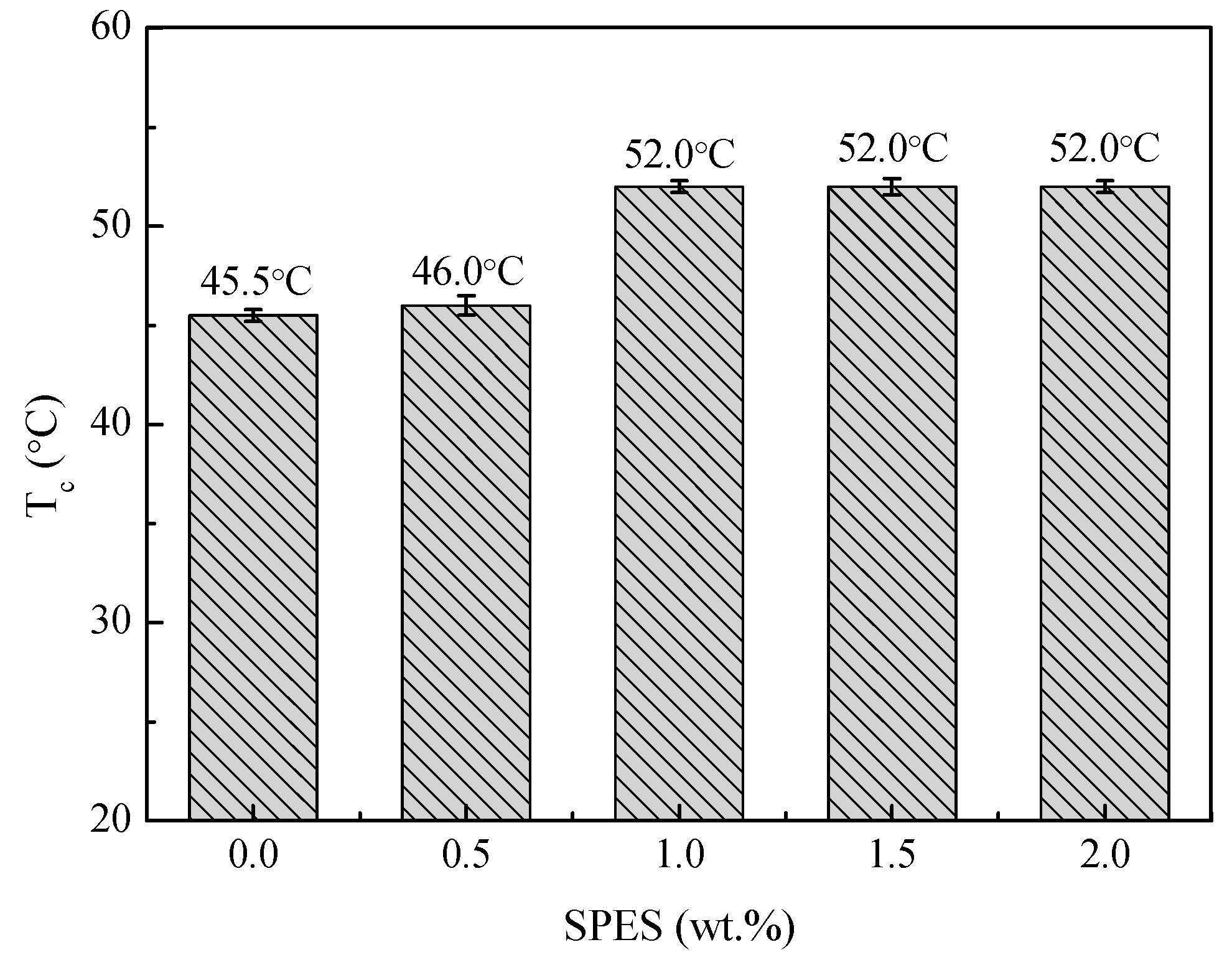
3.1. Cloud Point
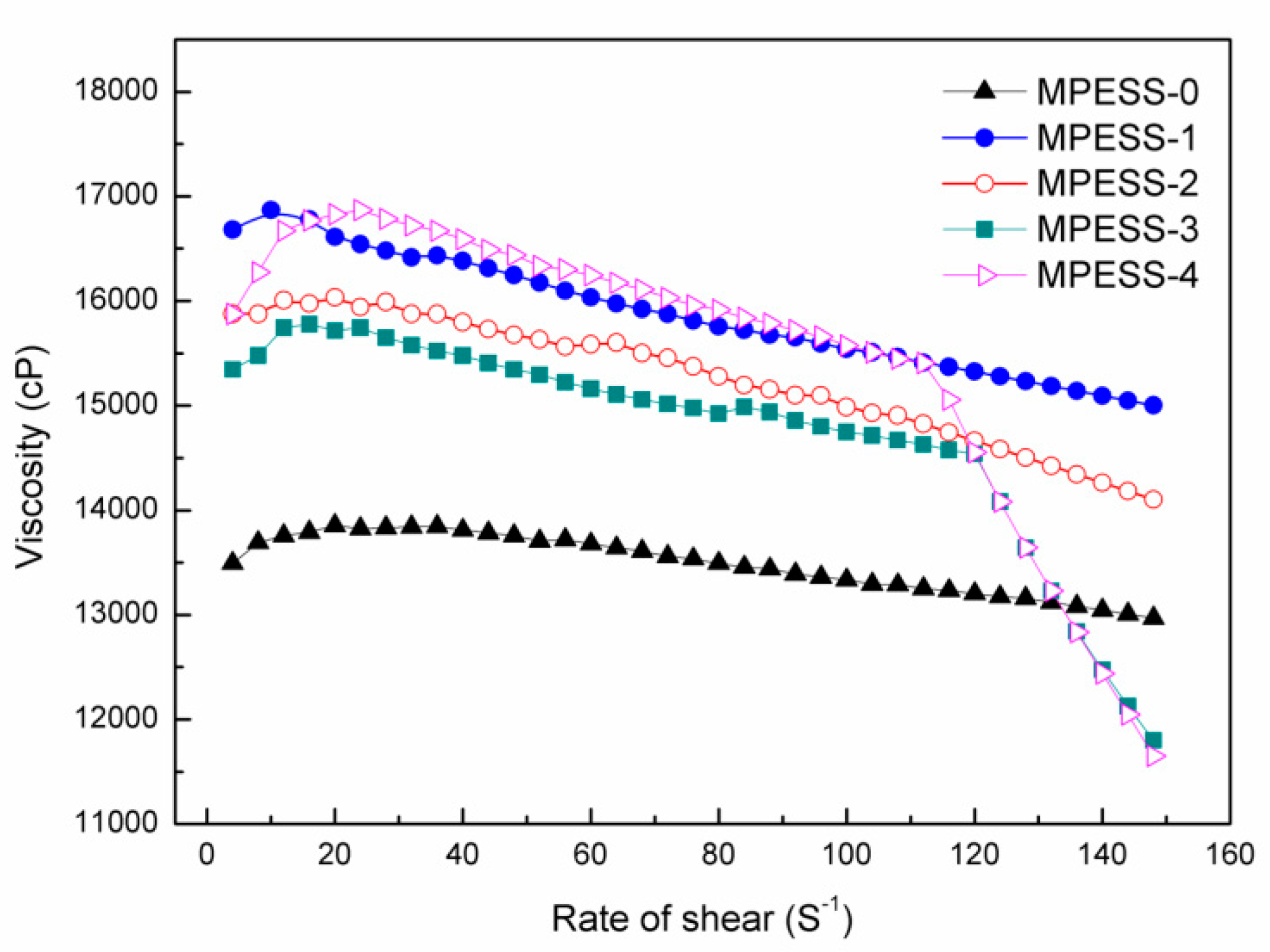
3.2. Viscosity
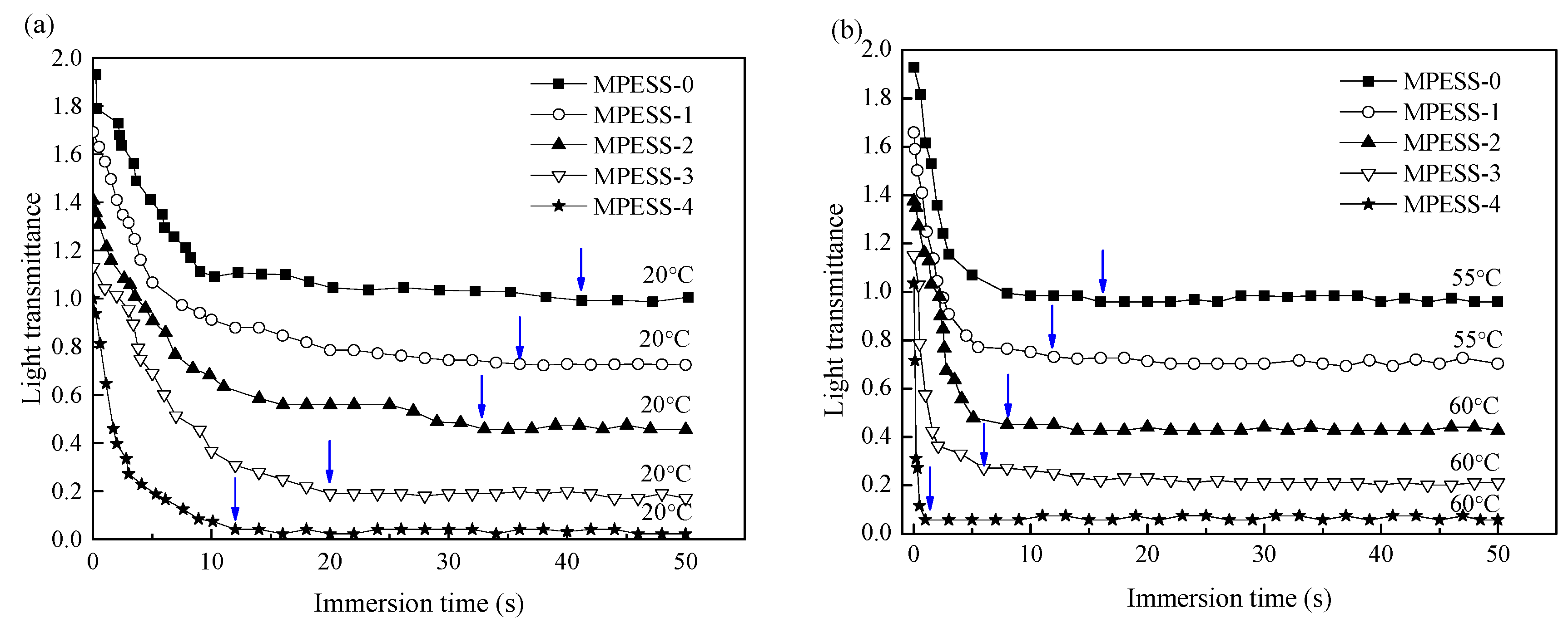
3.3. Light Transmittance Measurement
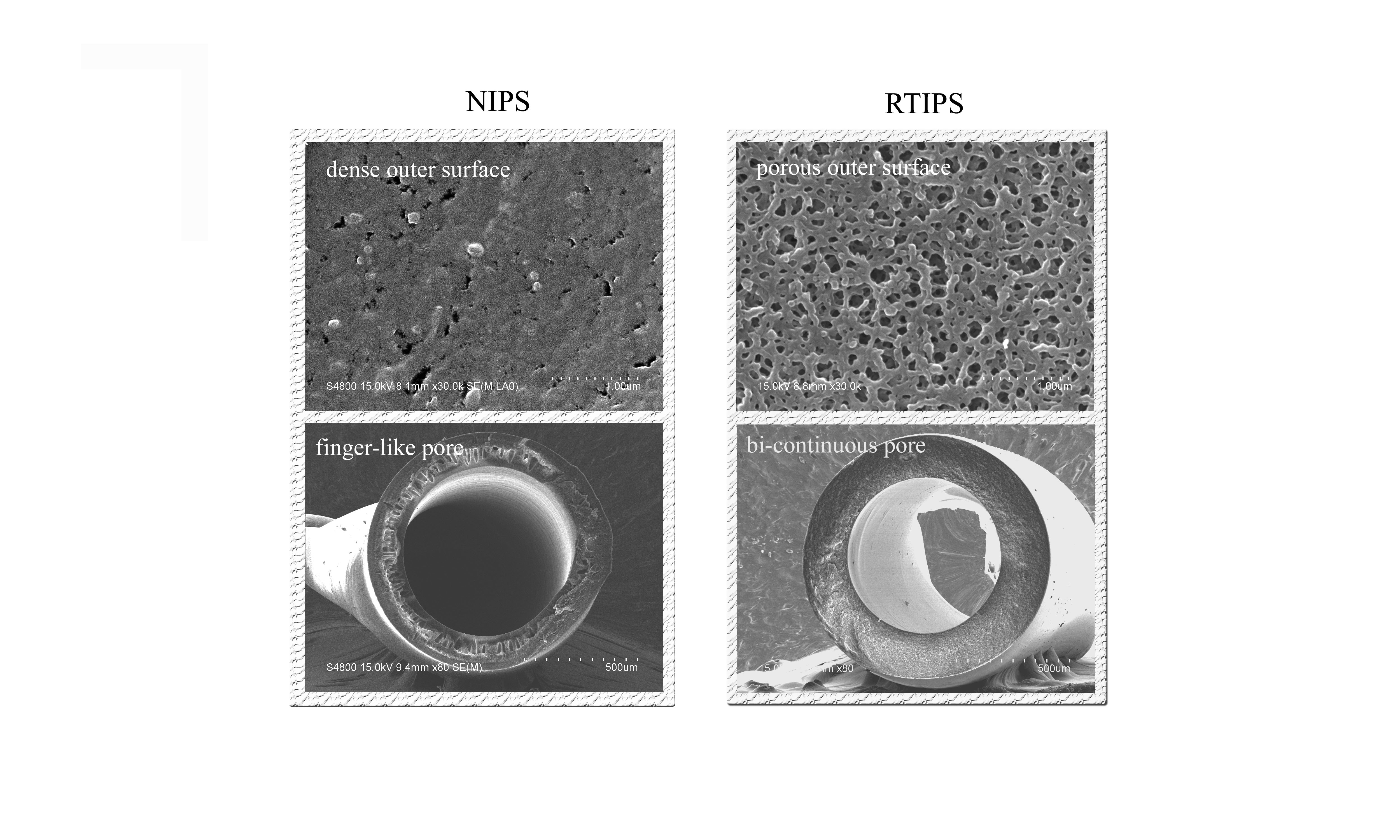
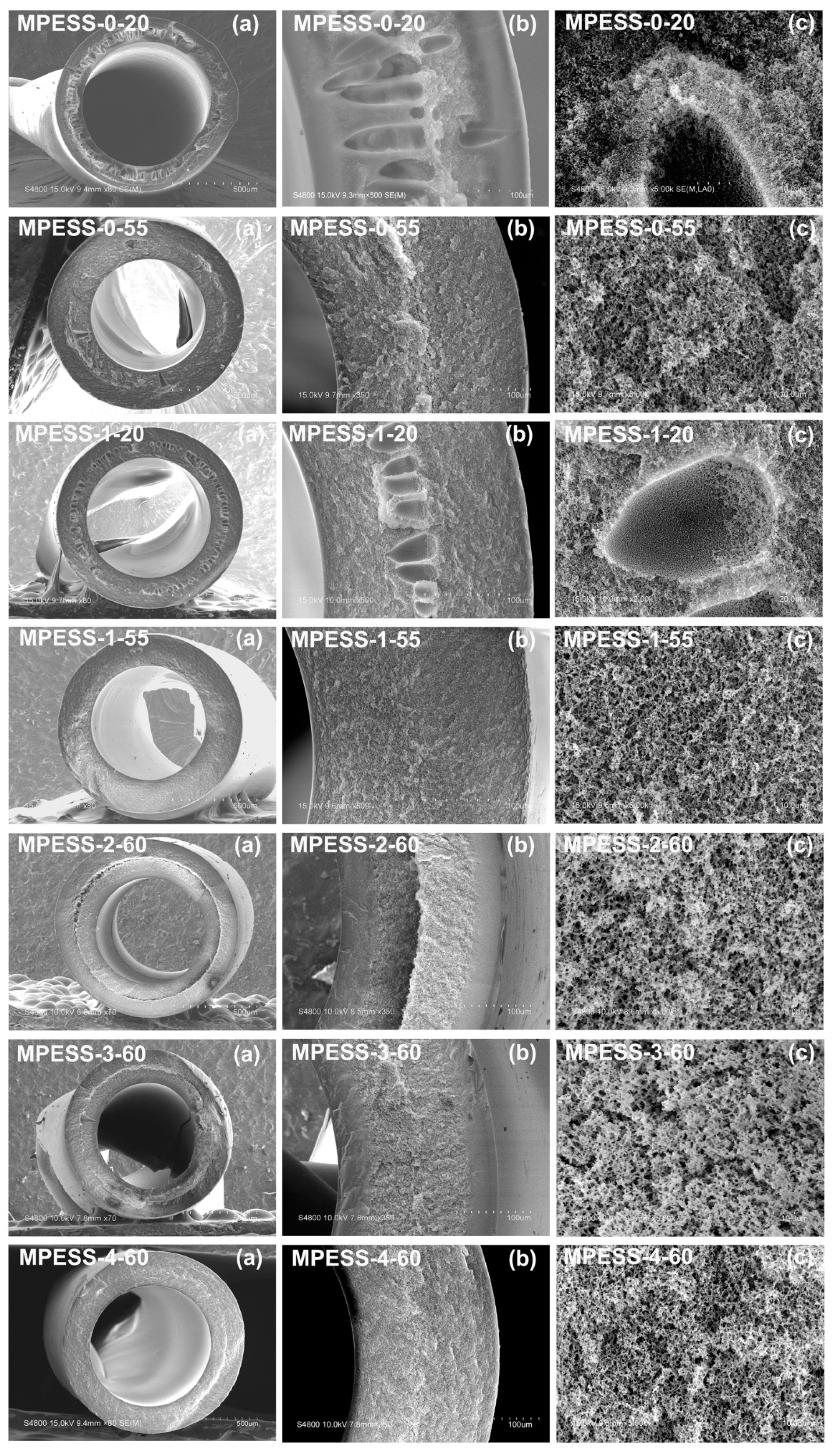
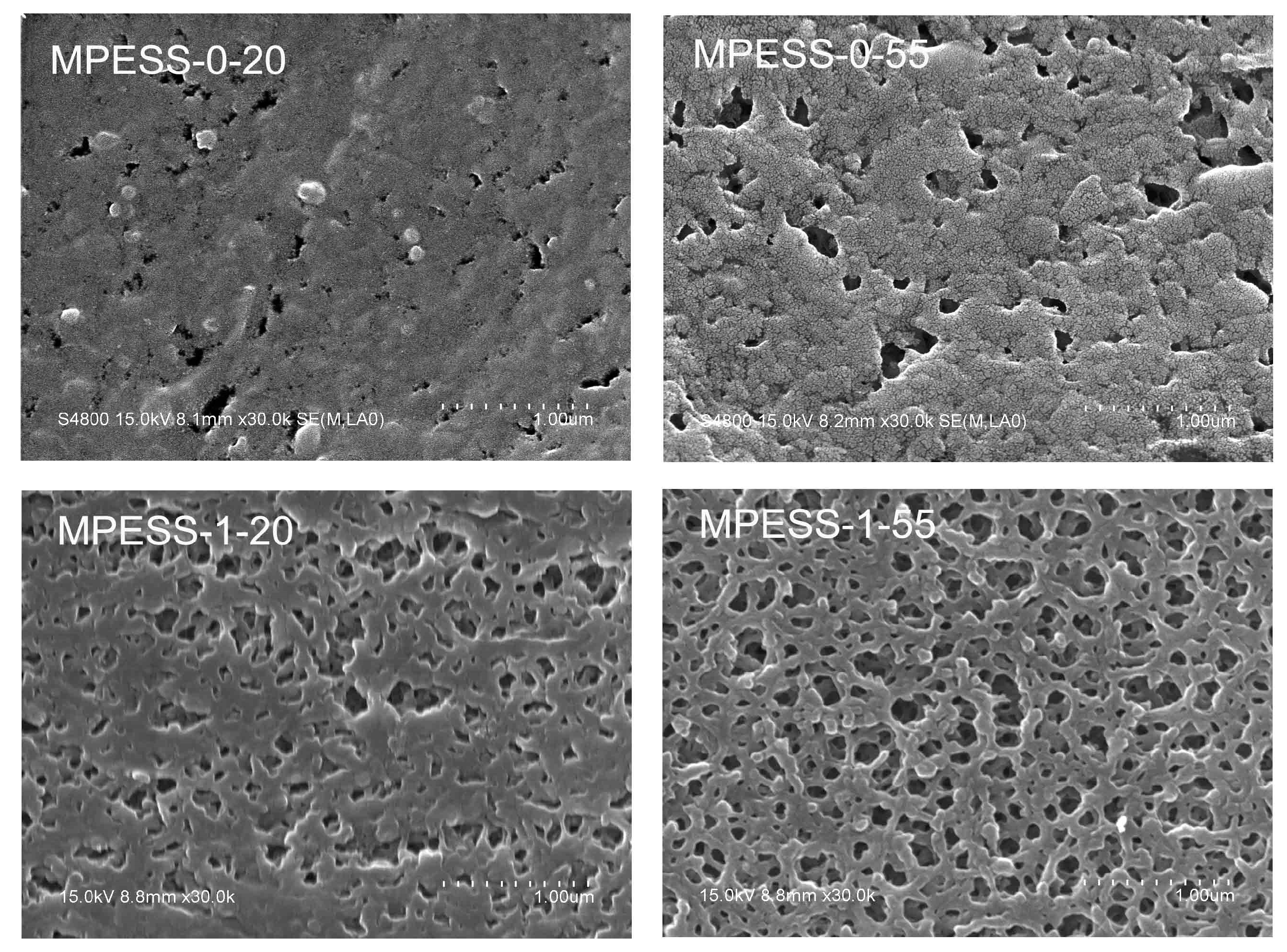
3.4. Membrane Morphology
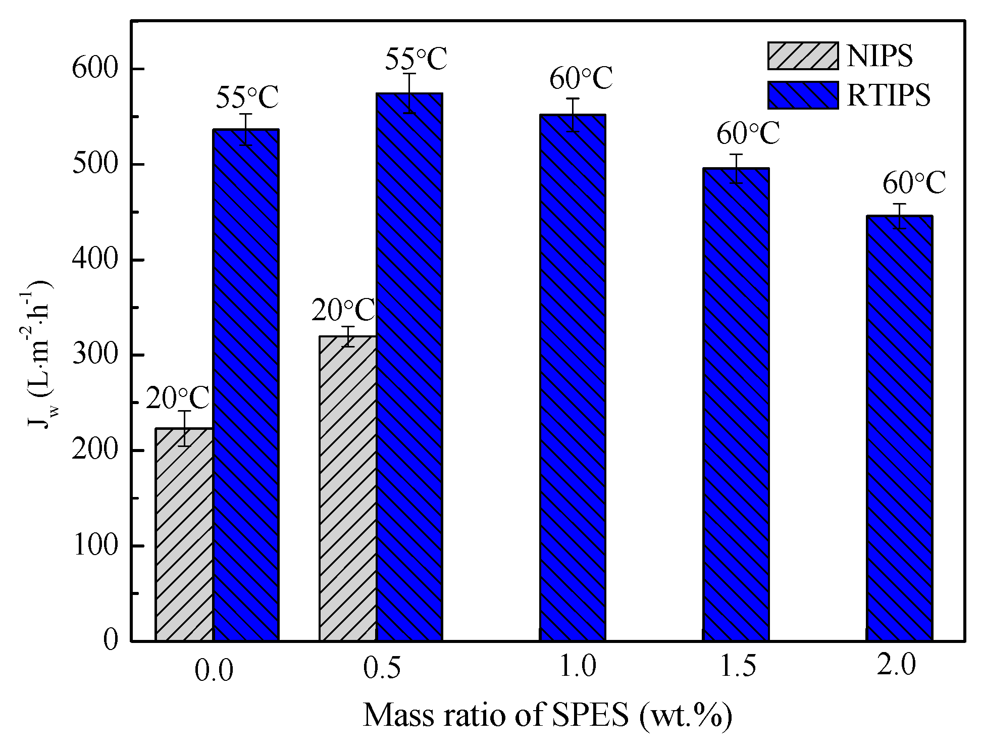
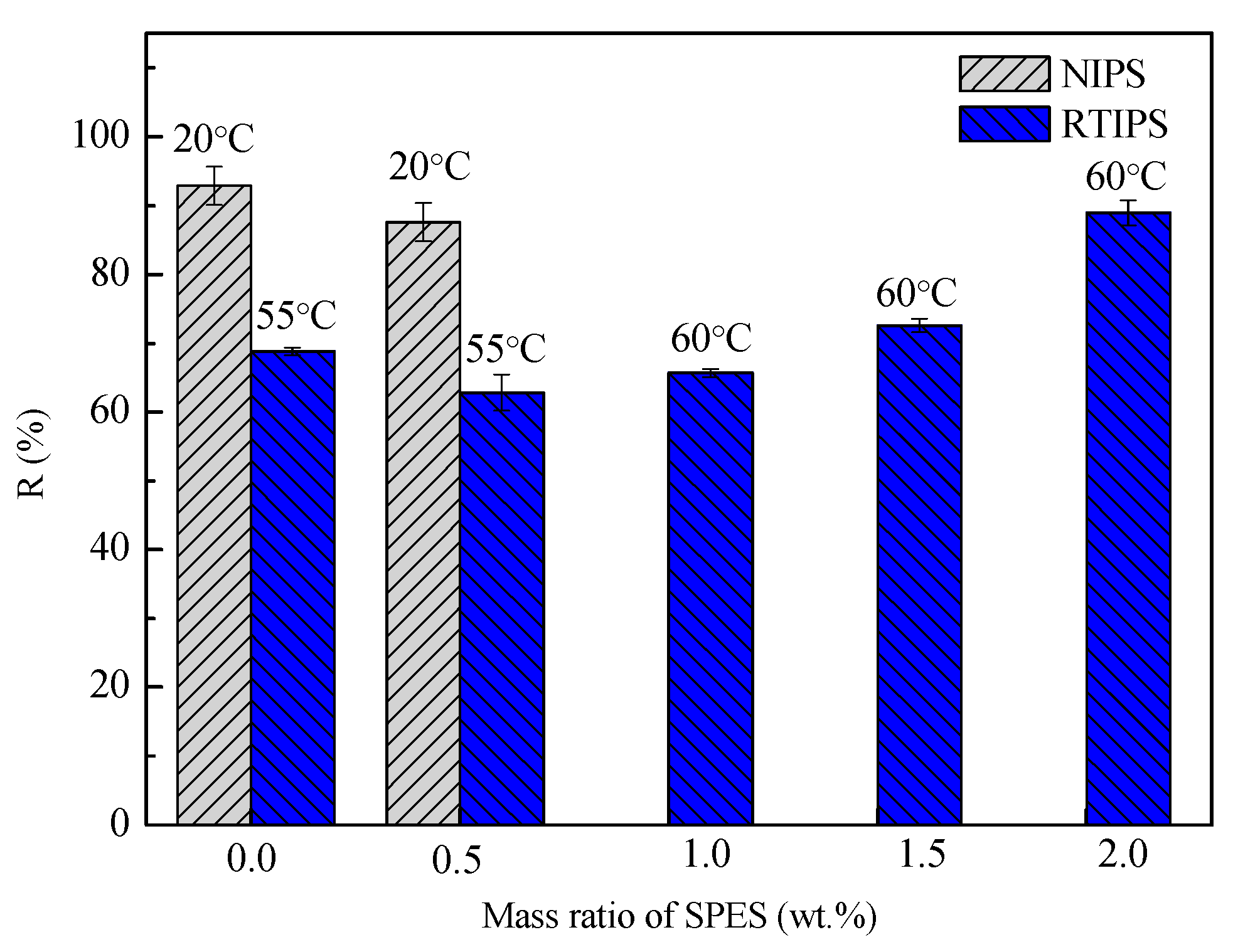
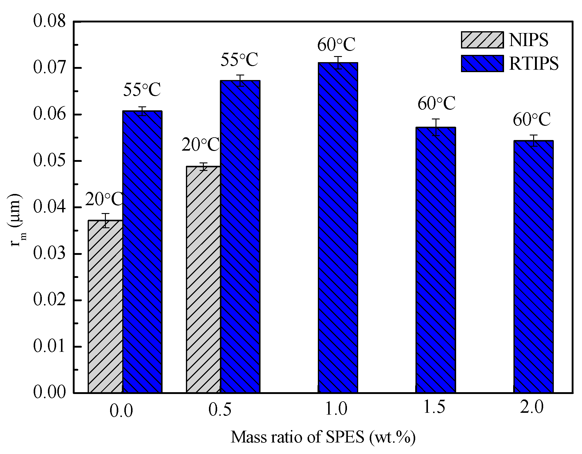
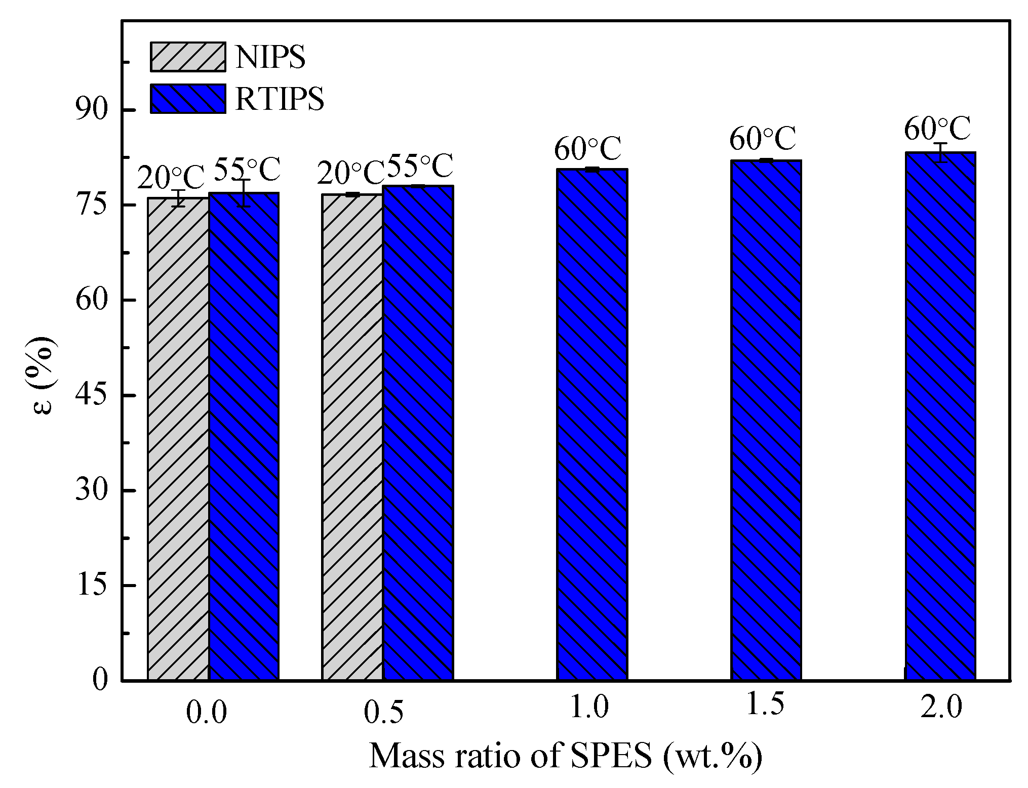
3.5. Permeation Properties, Porosity and Pore Size
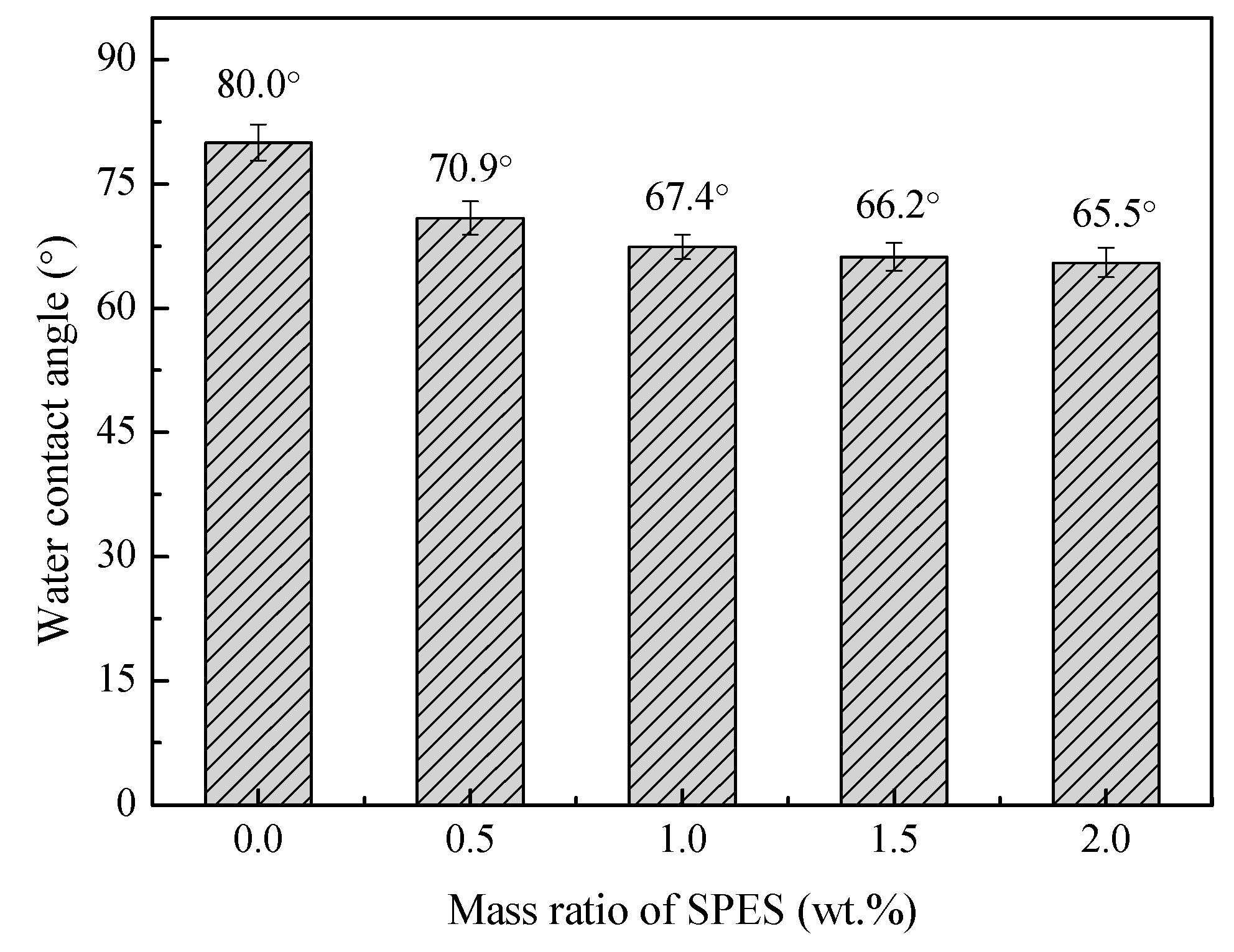
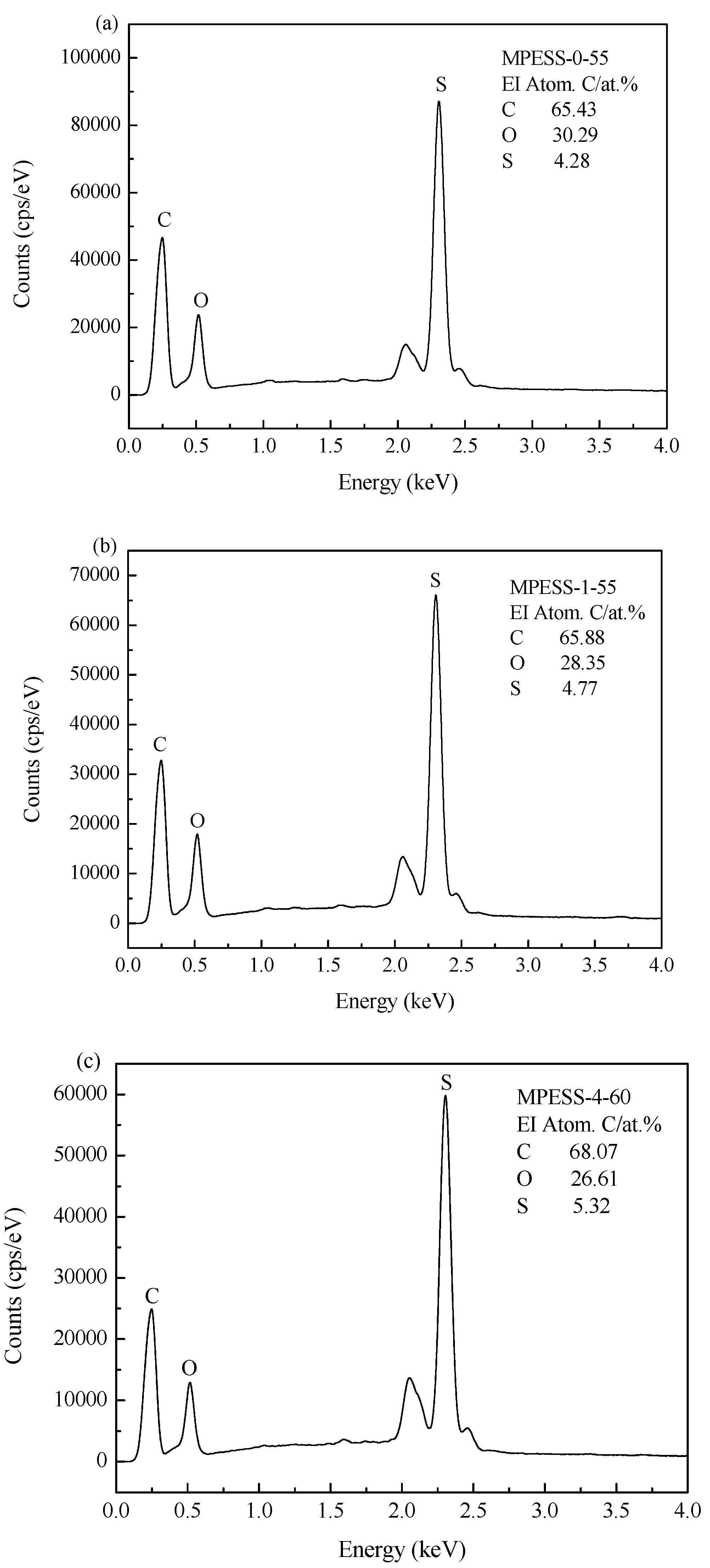
3.6. Hydrophilicity and EDX Analysis
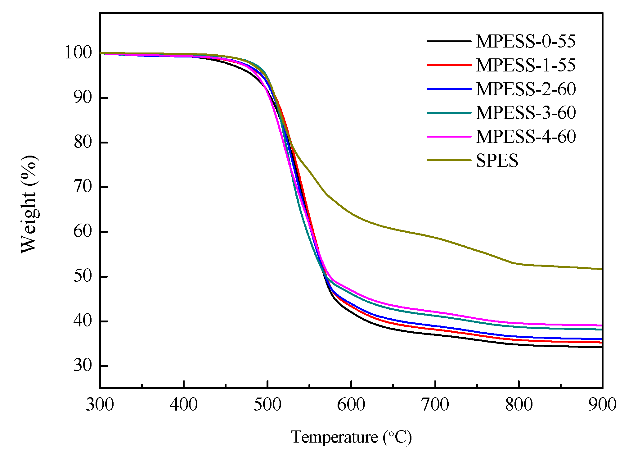
3.7. Thermal Stability
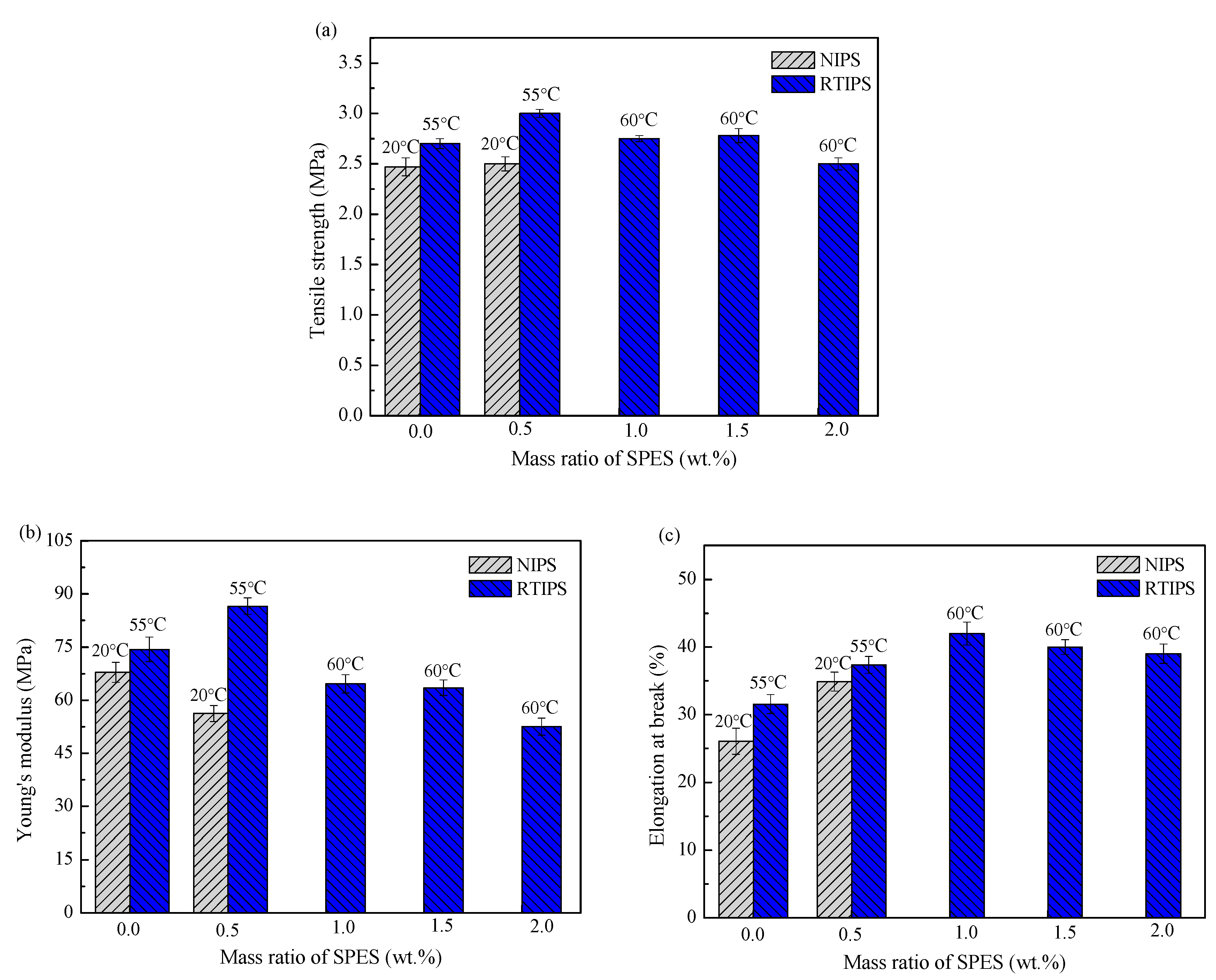
3.8. Mechanical Properties
4. Conclusions
Author Contributions
Funding
Acknowledgments
Conflicts of Interest
References
- Torrestiana-Sanchez, B.; Qrtiz-Basurto, R.I.; Fuente, E.B.-D.L. Effect of nonsolvents on properties of spinning solutions and polyethersulfone hollow fiber ultrafiltration membranes. J. Membr. Sci. 1999, 152, 19–28. [Google Scholar] [CrossRef]
- Chaturvedi, B.K.; Ghosh, A.K.; Ramachandhran, V.; Trivedi, M.K.; Hanra, M.S.; Misra, B.M. Preparation, characterization and performance of polyethersulfone ultrafiltration membranes. Desalination 2001, 133, 31–40. [Google Scholar] [CrossRef]
- Barzin, J.; Sadatnia, B. Theoretical phase diagram calculation and membrane morphology evaluation for water/solvent/polyethersulfone systems. Polymer 2007, 48, 1620–1631. [Google Scholar] [CrossRef]
- Madaeni, S.S.; Bakhtiari, L. Thermodynamic-based predictions of membrane morphology in water/dimethylsulfoxide/polyethersulfone systems. Polymer 2012, 53, 4481–4488. [Google Scholar] [CrossRef]
- Gu, Y.; Miki, N. Multilayered microfilter using a nanoporous PES membrane and applicable as the dialyzer of a wearable artificial kidney. J. Micromech. Microeng. 2009, 19, 065031. [Google Scholar] [CrossRef]
- Nie, C.X.; Ma, L.; Xia, Y.; He, C.; Deng, J.; Wang, L.R.; Cheng, C.; Sun, S.D.; Zhao, C.S. Novel heparin-mimicking polymer brush grafted carbon nanotube/PES composite membranes for safe and efficient blood purification. J. Membr. Sci. 2015, 475, 455–468. [Google Scholar] [CrossRef]
- Wang, C.; Wang, R.; Xu, Y.; Zhang, M.; Yang, F.; Sun, S.D.; Zhao, C.S. A facile way to prepare anti-fouling and blood-compatible polyethersulfone membrane via blending with heparin- mimicking polyurethanes. Mater. Sci. Eng. C 2017, 78, 1035–1045. [Google Scholar] [CrossRef]
- Guan, R.; Zou, H. Polyethersulfone sulfonated by chlorosulfonic acid and mits membrane characteristics. Eur. Polym. J. 2005, 41, 1554–1560. [Google Scholar] [CrossRef]
- Zhao, C.S.; Xue, J.M.; Ran, F.; Sun, S.D. Modification of polyethersulfone membranes-A review of methods. Pro. Mater. Sci. 2013, 58, 76–150. [Google Scholar] [CrossRef]
- Zhu, L.J.; Zhu, L.P.; Jiang, J.H.; Yi, Z.; Zhao, Y.F.; Zhu, B.K.; Xu, Y.Y. Hydrophilic and anti-fouling polyethersulfone ultrafiltration membranes with poly(2-hydroxyethylmethacrylate) grafted silica nanoparticles as additive. J. Membr. Sci. 2014, 451, 157–168. [Google Scholar] [CrossRef]
- Liu, D.P.; Wang, T.B.; He, C.J. Antifouling polyethersulfone membrane blended with a dual-mode amphiphilic copolymer. J Mater. Sci. 2016, 51, 7383–7394. [Google Scholar] [CrossRef]
- Xie, Y.; Chen, S.Q.; Qian, Y.H.; Zhao, W.F.; Zhao, C.S. Photo-responsive membrane surface: Switching from bactericidal to bacterial-resistant property. Mater. Sci. Eng. C 2018, 84, 52–59. [Google Scholar] [CrossRef] [PubMed]
- Jo, Y.J.; Choi, E.Y.; Kim, S.W.; Kim, C.K. Fabrication and characterization of a novel polyethersulfone/aminated polyethersulfone ultrafiltration membrane assembled with zinc oxide nanoparticles. Polymer 2016, 87, 290–299. [Google Scholar] [CrossRef]
- Belfer, S.; Fainchtain, R.; Purinson, Y.; Kedem, O. Surface characterization by FTIR-ATR spectroscopy of polyethersulfone membranes-unmodified, modified and protein fouled. J. Membr. Sci. 2000, 172, 113–124. [Google Scholar] [CrossRef]
- Weinman, S.T.; Bass, M.; Pandit, S.; Herzberg, M.; Fregerb, V.; Husson, S.M. A switchable zwitterionic membrane surface chemistry for biofouling control. J. Membr. Sci. 2018, 548, 490–501. [Google Scholar] [CrossRef]
- Ng, L.Y.; Ahmad, A.; Mohammad, A.W. Alteration of polyethersulphone membranes through UV-induced modification using various materials: A brief review. Arab. J. Chem. 2017, 10, S1821–S1834. [Google Scholar] [CrossRef]
- Li, J.F.; Xu, Z.L.; Yang, H.; Yu, L.Y.; Liu, M. Effect of TiO2 nanoparticles on the surface morphology and performance of microporous PES membrane. Appl. Surf. Sci. 2009, 255, 4725–4732. [Google Scholar] [CrossRef]
- Susanto, H.; Ulbrichta, M. Characteristics, performance and stability of polyethersulfone ultrafiltration membranes prepared by phase separation method using different macromolecular additives. J. Membr. Sci. 2009, 327, 125–135. [Google Scholar] [CrossRef]
- Ma, Y.X.; Shi, F.M.; Ma, J.; Wu, M.N.; Zhang, J.; Gao, C.J. Effect of PEG additive on the morphology and performance of polysulfone ultrafiltration membranes. Desalination 2011, 272, 51–58. [Google Scholar] [CrossRef]
- Qadir, D.; Mukhtar, H.; Keong, L.K. Synthesis and characterization of polyethersulfone/carbon molecular sieve based mixed matrix membranes for water treatment applications. Procedia Eng. 2016, 148, 588–593. [Google Scholar] [CrossRef]
- Han, S.J.; Mao, L.L.; Wu, T.; Wang, H.Z. Homogeneous polyethersulfone hybrid membranes prepared with in-suit synthesized magnesium hydroxide nanoparticles by phase inversion method. J. Membr. Sci. 2016, 516, 47–55. [Google Scholar] [CrossRef]
- Cheng, Z.L.; Li, X.; Liu, Y.D.; Chung, T.S. Robust outer-selective thin-film composite polyethersulfone hollow fiber membranes with low reverse salt flux for renewable salinity-gradient energy generation. J. Membr. Sci. 2016, 506, 119–129. [Google Scholar] [CrossRef]
- Nasrollahi, N.; Vatanpour, V.; Aber, S.; Mahmoodi, N.M. Preparation and characterization of a novel polyethersulfone (PES) ultrafiltration membrane modified with a CuO/ZnO nanocomposite to improve permeability and antifouling properties. Sep. Purif. Technol. 2018, 192, 369–382. [Google Scholar] [CrossRef]
- Abdel-Karim, A.; Leaper, S.; Alberto, M.; Vijayaraghavan, A.; Fan, X.L.; Holmes, S.M.; Souaya, E.R.; Badawy, M.I.; Gorgojo, P. High flux and fouling resistant flat sheet polyethersulfone membranes incorporated with graphene oxide for ultrafiltration applications. Chem. Eng. J. 2018, 334, 789–799. [Google Scholar] [CrossRef]
- Liu, M.; Wei, Y.M.; Xu, Z.L.; Guo, R.Q.; Zhao, L.B. Preparation and characterization of polyethersulfone microporous membrane via thermally induced phase separation with low critical solution temperature system. J. Membr. Sci. 2013, 437, 169–178. [Google Scholar] [CrossRef]
- Zhao, L.B.; Liu, M.; Xu, Z.L.; Wei, Y.M.; Xu, M.X. PSF hollow fiber membrane fabricated from PSF-HBPE-PEG400-DMAc dope solutions via reverse thermally induced phase separation. Chem. Eng. Sci. 2015, 137, 131–139. [Google Scholar] [CrossRef]
- Liu, S.H.; Liu, M.; Xu, Z.L.; Wei, Y.M. A novel PES-TiO2 hollow fiber hybrid membrane prepared via sol-gel process assisted reverse thermally induced phase separation (RTIPS) method. J. Membr. Sci. 2017, 528, 303–315. [Google Scholar] [CrossRef]
- Liu, S.H.; Xu, Z.L.; Liu, M.; Wei, Y.M.; Guo, F. Preparation and characterization of PES/CA microporous membranes via reverse thermally induced phase separation process. Polym. Eng. Sci. 2018, 58, 180–191. [Google Scholar] [CrossRef]
- Liu, S.H.; Liu, M.; Xu, Z.L.; Wei, Y.M. A polyethersulfone-bisphenol sulfuric acid hollow fiber ultrafiltration membrane fabricated by a reverse thermally induced phase separation process. RSC Adv. 2018, 8, 7800–7809. [Google Scholar] [CrossRef]
- Liu, M.; Liu, S.H.; Skov, A.L.; Xu, Z.L. Estimation of phase separation temperatures for polyethersulfone/solvent/non-solvent systems in RTIPS and membrane properties. J. Membr. Sci. 2018, 556, 329–341. [Google Scholar] [CrossRef]
- Klaysom, C.; Ladewig, B.P.; Lu, G.Q.M.; Wang, L.Z. Preparation and characterization of sulfonated polyethersulfone for cation-exchange membranes. J. Membr. Sci. 2011, 368, 48–53. [Google Scholar] [CrossRef]
- Zhao, W.F.; Mou, Q.B.; Zhang, X.X.; Shi, J.Y.; Sun, S.D.; Zhao, C.S. Preparation and characterization of sulfonated polyethersulfone membranes by a facile approach. Eur. Polym. J. 2013, 49, 738–751. [Google Scholar] [CrossRef]
- Muthumeenal, A.; Neelakandan, S.; Kanagaraj, P.; Nagendran, A. Synthesis and properties of novel proton exchange membranes based on sulfonated polyethersulfone and N-phthaloyl chitosan blends for DMFC applications. Renew. Energy 2016, 86, 922–929. [Google Scholar] [CrossRef]
- Albo, J.; Wang, J.H.; Tsuru, T. Gas transport properties of interfacially polymerized polyamide composite membranes under different pre-treatments and temperatures. J. Membr. Sci. 2014, 449, 109–118. [Google Scholar] [CrossRef]
- Albo, J.; Hagiwara, H.; Yanagishita, H.; Ito, K.; Tsuru, T. Structural characterization of thin-film polyamide reverse osmosis membranes. Ind. Eng. Chem. Res. 2014, 53, 1442–1451. [Google Scholar] [CrossRef]
- Albo, J.; Wang, J.H.; Tsuru, T. Application of interfacially polymerized polyamide composite membranes to isopropanol dehydration: Effect of membrane pre-treatment and temperature. J. Membr. Sci. 2014, 453, 384–393. [Google Scholar] [CrossRef]
- Lang, W.Z.; Xu, Z.L.; Yang, H.; Tong, W. Preparation and characterization of PVDF-PFSA blend hollow fiber UF membrane. J. Membr. Sci. 2007, 288, 123–131. [Google Scholar] [CrossRef]
- Wang, Y.J.; Kim, D. Crystallinity, morphology, mechanical properties and conductivity study of in situ formed PVdF/LiClO4/TiO2 nanocomposite polymer electrolytes. Electrochim. Acta 2007, 52, 3181–3189. [Google Scholar] [CrossRef]
- Feng, C.S.; Shi, B.L.; Li, G.M.; Wu, Y.L. Preparation and properties of microporous membrane from poly(vinylidene fluoride-co-tetrafluoroethy-lene) (F2.4) for membrane distillation. J. Membr. Sci. 2004, 237, 15–24. [Google Scholar] [CrossRef]


| Casting Solutions | Casting Solution Compositions (wt.%) | |||
|---|---|---|---|---|
| PES | SPES | DMAc | PEG200 | |
| MPESS-0 | 17.0 | 0 | 20.75 | 62.25 |
| MPESS-1 | 16.5 | 0.5 | 20.75 | 62.25 |
| MPESS-2 | 16.0 | 1.0 | 20.75 | 62.25 |
| MPESS-3 | 15.5 | 1.5 | 20.75 | 62.25 |
| MPESS-4 | 15.0 | 2.0 | 20.75 | 62.25 |
| Membranes | Internal and External Bath Temperature (°C) |
|---|---|
| MPESS-0-20 | 20 |
| MPESS-0-55 | 55 |
| MPESS-1-20 | 20 |
| MPESS-1-55 | 55 |
| MPESS-2-60 | 60 |
| MPESS-3-60 | 60 |
| MPESS-4-60 | 60 |
| Membranes | MPESS-0-55 | MPESS-1-55 | MPESS-2-60 | MPESS-3-60 | MPESS-4-60 | SPES |
|---|---|---|---|---|---|---|
| Tdon (°C) | 500.8 | 500.0 | 496.9 | 497.1 | 490.3 | 492.1 |
| Tdpeak (°C) | 551.2 | 539.0 | 528.0 | 523.6 | 516.1 | 514.7 |
© 2019 by the authors. Licensee MDPI, Basel, Switzerland. This article is an open access article distributed under the terms and conditions of the Creative Commons Attribution (CC BY) license (http://creativecommons.org/licenses/by/4.0/).
Share and Cite
Liu, M.; Ladegaard Skov, A.; Liu, S.-H.; Yu, L.-Y.; Xu, Z.-l. A Facile Way to Prepare Hydrophilic Homogeneous PES Hollow Fiber Membrane via Non-Solvent Assisted Reverse Thermally Induced Phase Separation (RTIPS) Method. Polymers 2019, 11, 269. https://doi.org/10.3390/polym11020269
Liu M, Ladegaard Skov A, Liu S-H, Yu L-Y, Xu Z-l. A Facile Way to Prepare Hydrophilic Homogeneous PES Hollow Fiber Membrane via Non-Solvent Assisted Reverse Thermally Induced Phase Separation (RTIPS) Method. Polymers. 2019; 11(2):269. https://doi.org/10.3390/polym11020269
Chicago/Turabian StyleLiu, Min, Anne Ladegaard Skov, Sheng-Hui Liu, Li-Yun Yu, and Zhen-liang Xu. 2019. "A Facile Way to Prepare Hydrophilic Homogeneous PES Hollow Fiber Membrane via Non-Solvent Assisted Reverse Thermally Induced Phase Separation (RTIPS) Method" Polymers 11, no. 2: 269. https://doi.org/10.3390/polym11020269