Article

Study on Growth Interface of Large Nd:YAG Crystals

Guangzhou Semiconductor Material Academy, Guangzhou 510610, China
*
Author to whom correspondence should be addressed.
Crystals 2023, 13(6), 970; https://doi.org/10.3390/cryst13060970
Submission received: 23 April 2023 / Revised: 12 June 2023 / Accepted: 13 June 2023 / Published: 19 June 2023
(This article belongs to the Special Issue Emerging Rare-Earth Doped Materials)

Abstract

:
A study was performed on the growth interface of a large-diameter 1 at% neodymium-doped yttrium aluminum garnet (Nd:YAG) single crystal grown using the Czochralski method. Red parallel light and an orthogonal polarizing system were used to observe the distribution of the central and lateral cores of the crystal at different growth interfaces. The solid–liquid interface of large-diameter Nd:YAG crystal growth was mainly determined via the interaction between natural and forced convection. The shape of the solid–liquid interface was mainly controlled via maintaining the crystal rotation rate and the temperature field. Interface inversion generally occurred during the shoulder-expanding stage and late stages of the growth of the cylindrical portion of the crystal. The occurrence of interface inversion is directly related to the temperature field, process parameters, and diameter of the crystal. The growth shape of the crystal interface determined the size and distribution of the central and lateral cores of the crystal. The area of the central and lateral cores was reduced via adjusting the temperature gradient of the solid–liquid interface and crystal rotation speed.

1. Introduction

Doped yttrium aluminum garnet (YAG) crystals are still the popular material for solid lasers and are the first working material to be used for high-power solids, owing to their good optical uniformity, excellent mechanical and chemical stability, good thermal conductivity, and feasibility for industrial production [1,2,3,4,5]. Currently, a gradual increase in the application of high-power all-solid-state lasers has accelerated the development of solid-state lasers toward high power levels, efficiency, and beam quality. Consequently, the demand for high-quality, large, neodymium-doped YAG (Nd:YAG) laser crystals has grown rapidly [6,7]. The shape of the crystal growth interface plays an important role in crystal quality. The key technology for realizing high-quality, large-diameter Nd:YAG crystals is maintaining the stability of solid–liquid interface shape during the growth process. The shape of the solid–liquid interface is related to the crystal growth mechanism, crystal growth kinetics, and mass and heat transfer in the melt. The interface provides a window for viewing the crystal growth mechanism and kinetics, as well as fundamental phenomena [8] of crystal growth, which are of extraordinary significance for understanding the shape of the solid–liquid interface. In recent years, a few studies have been conducted on the solid–liquid interface of large YAG crystals, most of which are performed using numerical simulations [9,10,11]. There is a lack of reliable experimental data to validate the simulation results related to crystal growth, and multiple problems have not been thoroughly examined. Therefore, to improve the quality of large grown crystals, the interface shape of large Nd:YAG crystals grown using the Czochralski (CZ) method should be studied and the relationship between crystal defects and growth interfaces should be elucidated.
In this study, for the first time, several experiments were performed to investigate the relationship between the growth interface of large Nd:YAG crystals and the crystal rotation rate, as well as the temperature field. The results of this study provide guidance on how to improve the quality of large Nd:YAG crystals.

2. Experimental

2.1. Crystal Growth

Nd:YAG laser crystals were grown using the CZ method in an iridium crucible heated via radio-frequency induction. The raw materials of Y2O3 (5N), Al2O3 (5N), and Nd2O3 (6N) were weighed as per the formula (Y1−xNdx)3Al5O12, where x = 0.01. Then, the weighed raw materials were thoroughly mixed, pressed into a cylinder, and calcined at 1300 °C for 48 h. Finally, the burned materials were placed in an iridium crucible. Subsequently, the crystals were grown in a DJL-800 furnace (BOET, Beijing, China) at 1970 °C. An Ir crucible (diameter: 160 mm and height: 160 mm) was selected as the heating element. Nd:YAG seed crystals in the <111> direction were selected to grow crystals in an Ar atmosphere.

2.2. Central and Lateral Cores Observation

Nd:YAG crystal boules were selected as the experimental samples, and parts of crystals with the same diameter were obtained by cutting the head and tail of the boules. The central and lateral cores of the crystal were observed using a red parallel light source (Model LP-80, Shenzhen HB Laser Ltd., Shenzhen, China). An orthogonal polarizing system (PSV-201, Suzhou PTC Optical Instrument Co., Ltd., Suzhou, China) was used to measure the stress induced by central and lateral cores of the crystal.

3. Results and Discussion

3.1. Natural and Forced Convection

Crystal growth occurs under non-isothermal conditions and/or concentration gradients. Inhomogeneities in the temperature of a fluid result in density variations in the system. Considering the gravity field, the buoyancy caused by density variations in the fluid is the driving force for natural convection, i.e., natural convection occurs when buoyancy overcomes the viscous force in a melt. Forced convection is primarily caused by crystal rotation. Crystal rotation causes the nearby fluid to achieve a certain acceleration and produce inertial forces. When these inertial forces are larger than the viscous force of the fluid itself is, forced convection occurs. An Nd:YAG crystal was grown via heating and melting a raw material via the medium-frequency induction heating of an Ir crucible. The radial temperature difference between the crucible wall and center drives natural convection. The larger the radial temperature gradient is, the stronger the natural convection is. When natural convection dominates forced convection, the shape of the solid–liquid interface becomes convex toward the melt. When the conditions of crystal growth remain unchanged, an increase in the crystal rotation speed causes the forced convection of the fluid in the crucible to gradually increase, the corresponding natural convection to weaken, and the solid–liquid interface to gradually become flat or concave.
Experiments were performed to determine the relationship between the crystal rotation rate and the characteristics of the growth interface. During the growth process, crystals of the same length were removed from the liquid surface and were labeled “a” or “b”. The rotation rate was 16–13 rpm for Crystal a and 18–15 rpm for Crystal b. Both types of crystals had a 65 mm diameter and a 100 mm long cylindrical portion. Figure 1 shows the central core distribution of Nd:YAG crystals grown under different crystal rotation velocities (rpma < rpmb) and the same temperature field using the orthogonal polarizing system, as shown by the arrow in Figure 1. Compared to the results for Crystal b, Crystal a has a clearly smaller central core area (i.e., Sa < Sb) and a more convex growth interface. Reducing the crystal rotation rate under certain conditions during the growth of large Nd:YAG crystals reduces the area of the central core.
However, for fixed pulling and crystal rotation rates, variations in the temperature field can affect the growth interface of crystals. To confirm this hypothesis, we studied the crystals growing on the shoulder under different temperatures. The crystal shown in Figure 2a was grown using a temperature gradient across the crucible mouth of ~1 °C/mm. The temperature gradient across the solid–liquid interface was subsequently increased by increasing the temperature gradient across the crucible mouth to ~15 °C/mm, resulting in the crystal shown in Figure 2b. The crystals shown in Figure 2a,b both have a 55 mm diameter. The growth interface of the crystal shown in Figure 2a is clearly flat, and the melt flow is non-uniform, reflecting the coexistence of forced and natural convection. The growth interface of the crystal shown in Figure 2b is convex, and the uniformity and symmetry of the liquid flow result in natural convection. During the growth of the Nd:YAG crystal, when the process parameters of crystal growth are consistent, the larger the temperature gradient at the solid–liquid interface is, and the more convex the growth interface is.
The CZ method with medium-frequency induction heating is used to grow large Nd:YAG crystals with a convex growth interface. To obtain high-quality crystals, an appropriate temperature distribution must be established in the crystal growth system. When the driving force produced by the temperature gradient across the crucible is consistent with gravity, natural convection is considered to be proportional to the dimensionless Rayleigh number, NRa [12].
N R a = α g G h 4 / k γ ,
where α is the coefficient of thermal expansion, g is the acceleration of gravity, G is the temperature gradient in the melt, h is the depth of the melt, k is the thermal diffusion coefficient, and γ is the viscosity coefficient of the flowing melt. Natural convection can be strengthened via increasing G and h. However, the liquid level in the crucible gradually decreases during the crystal growth process, indicating the slow weakening of natural convection. Natural convection cannot be strengthened by reducing h.
Forced convection in the melt is proportional to the dimensionless Reynolds number, NRe [12].
N R e = π ω d 2 γ 1 ,
where ω is the angular velocity of crystal rotation rate, d is the crystal diameter, and γ is the viscosity coefficient of the flowing melt. Equation (2) shows that forced convection can be strengthened by increasing the rotation rate and diameter of the crystal during the growth process. A convex interface can be maintained during the growth of Nd:YAG crystals using the CZ method with induction heating when natural convection is dominant [13]. However, during the second half of the crystal growth, the decreasing melt volume in the crucible and radiation from the exposed crucible wall to the crystal gradually weaken natural convection in the melt. To ensure that the growth interface of Nd:YAG crystals does not change, the crystal rotation speed should be properly decreased to reduce forced convection.
Hence, the shape of the solid–liquid interface during the growth of large Nd:YAG crystals is primarily attributed to the interaction between natural and forced convection. The balance between natural and forced convection in the melt is the combined effect of the crystal pulling speed, rotation speed, and thermal field surrounding the crystal. The shape of the growth interface can be maintained by slowly reducing the crystal rotation rate and adjusting the temperature gradient across the solid–liquid interface. We used the theoretical calculation presented above in conjunction with many adjustments of the crystal growth process and the temperature gradient across the solid–liquid interface to determine specific temperature conditions for maintaining a convex interface: a crystal diameter of 65 mm, crystal rotation rate of 16–10 rpm, and a temperature gradient across the crucible mouth of 15–18 °C/mm.

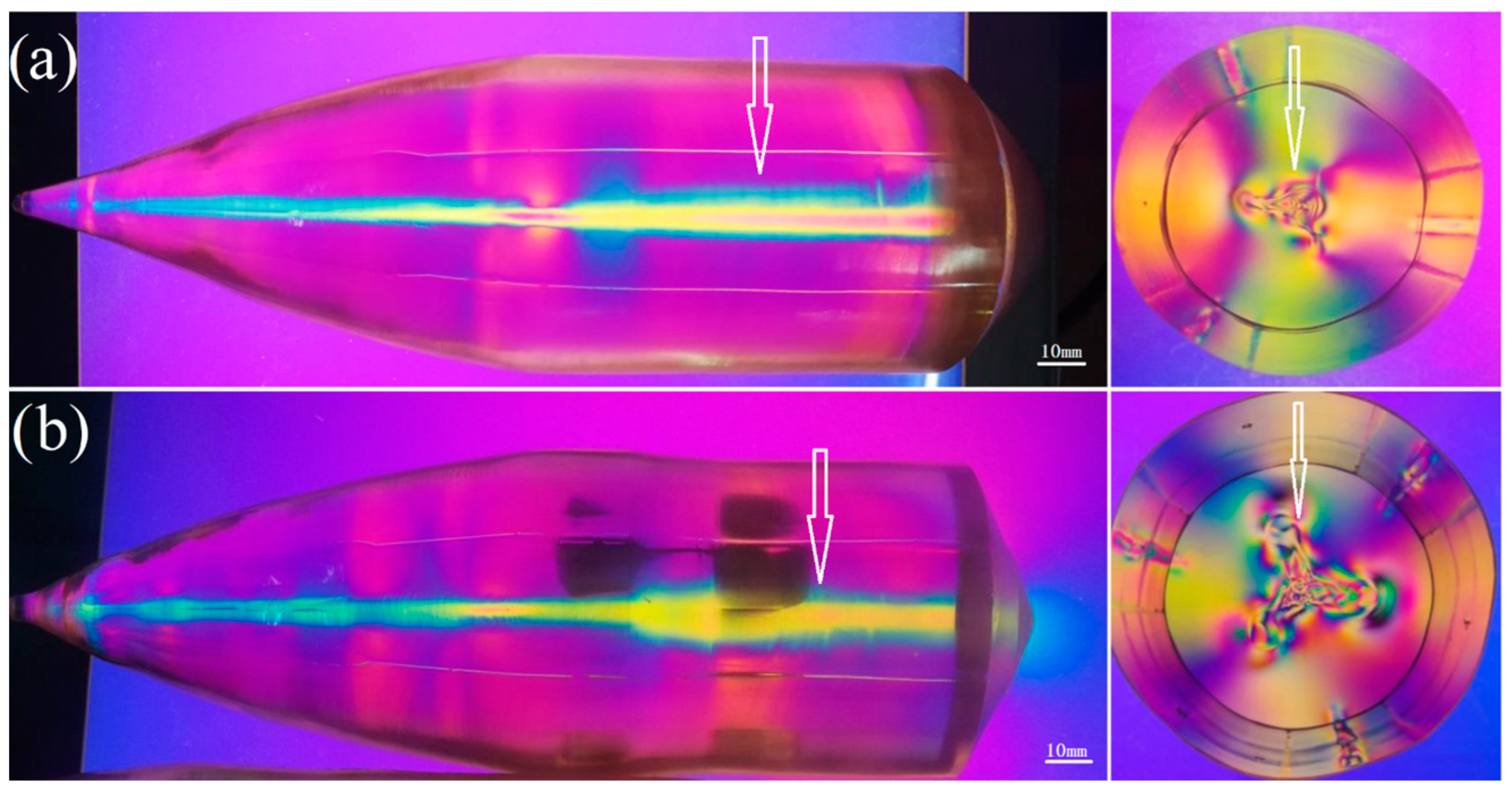
3.2. Interface Inversion

Analysis of the crystal growth interface revealed that forced and natural convection usually coexist in the melt. While fixing all other processing conditions, gradually increasing the rotation speed of crystals with a fixed diameter and size during equal-diameter growth will cause the melt to transition from being dominated by natural convection to being dominated by forced convection. The experimental results show that this transition in the convective state is sudden. The inversion of the solid–liquid interface is driven by the interaction between forced and natural convection, and the criterion for this state transition is given below [14].
d d c = ( g α Δ T R 3 π 2 ) 1 / 4 ω 1 / 2 ,
where dc is the critical diameter for the inversion of the crystal interface, g is the acceleration of gravity, α is the coefficient of the thermal expansion of the melt, R is the radius of the crucible, h is the depth of the melt, ∆T is the difference in the temperatures of the melt at the center and wall of the crucible, and ω is the crystal rotation rate.
Consequently, for a given growth system under a constant ω, increasing the crystal diameter, d, beyond dc causes the state of the fluid in the crucible to change from being dominated by natural convection to being dominated by forced convection. Once the melt undergoes this state transition, the crystal growth interface undergoes forced convection circulation; at this time, there is a sudden decrease in heat transfer to the solid–liquid interface, and the solid–liquid interface suddenly changes from convex to flat or concave, which is called interface inversion. Interface inversion causes the crystal to remelt. Interface inversion often occurs during the transition from crystal turning to equal-diameter growth or during the late phase of equal-diameter growth. During the late stage of equal-diameter growth, as the liquid level of the melt falls, radiation from the exposed crucible wall decreases the radial temperature difference, ∆T, across the crucible. Equation (3) shows that the critical diameter, d c , decreases as ∆T decreases, and interface inversion occurs when the crystal diameter becomes equal to d c . Similarly, the growth interface can be inverted by increasing the crystal rotation rate.
Interface inversion often occurs during preliminary experiments on Nd:YAG crystal growth. Figure 3 shows the interface inversion of the crystal during the late stage of shoulder growth, resulting in the sudden melting of the crystal. Apparently, the crystal growth interface appeared to be concave. The images obtained using the orthogonal polarizing system show that stress is distributed over an extremely large area inside the crystal.
Figure 4 shows interface inversion during the late stage of equal-diameter growth of the crystal. The crystal diameter increases suddenly (the measured diameter increases by 3 mm), which is accompanied by several scattered particles and stress distribution over a large area. As we used the automatic diameter-controlled method to control the crystal diameter, the sensor detected a signal of an increase in the crystal weight within a certain period of time; however, there was no indication of a sudden decrease in the crystal diameter after interface inversion. The remelting of the crystal resulted in the sensor detecting a signal of a sudden decrease in the crystal’s weight, followed by an error message of a sudden decrease in the crystal’s diameter. The temperature controller immediately increased the cooling rate after receiving the cooling signal, causing the crystal diameter to increase suddenly.
Interface inversion strongly affects the crystal quality and generally induces crystal defects. Thus, interface inversion during crystal growth should be prevented. The occurrence of interface inversion is directly related to the temperature field, process parameters, and diameter of the growing crystal. We performed multiple experiments and successfully eliminated interface inversion during the growth of large Nd:YAG crystals. The main measures for preventing interface inversion are given below.
  • A suitable temperature environment should be designed to maintain a considerably large temperature gradient across the crystal growth interface to ensure that the interface remains convex, and a temperature gradient of ~16 °C/mm above the liquid surface should be achieved during the initial stage of pulling.
  • During the entire crystal growth process, the crystal rotation speed should be controlled at 16–10 rpm to ensure that the growth interface remains convex.
  • A suitable crystal growth diameter should be designed; a 160 mm diameter iridium crucible can be used to grow an Nd:YAG crystal with a diameter below 65 mm. When the crystal diameter exceeds 65 mm, interface inversion can occur.

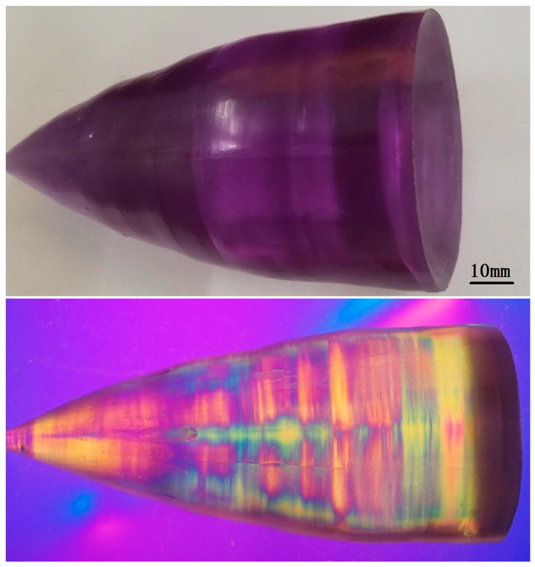
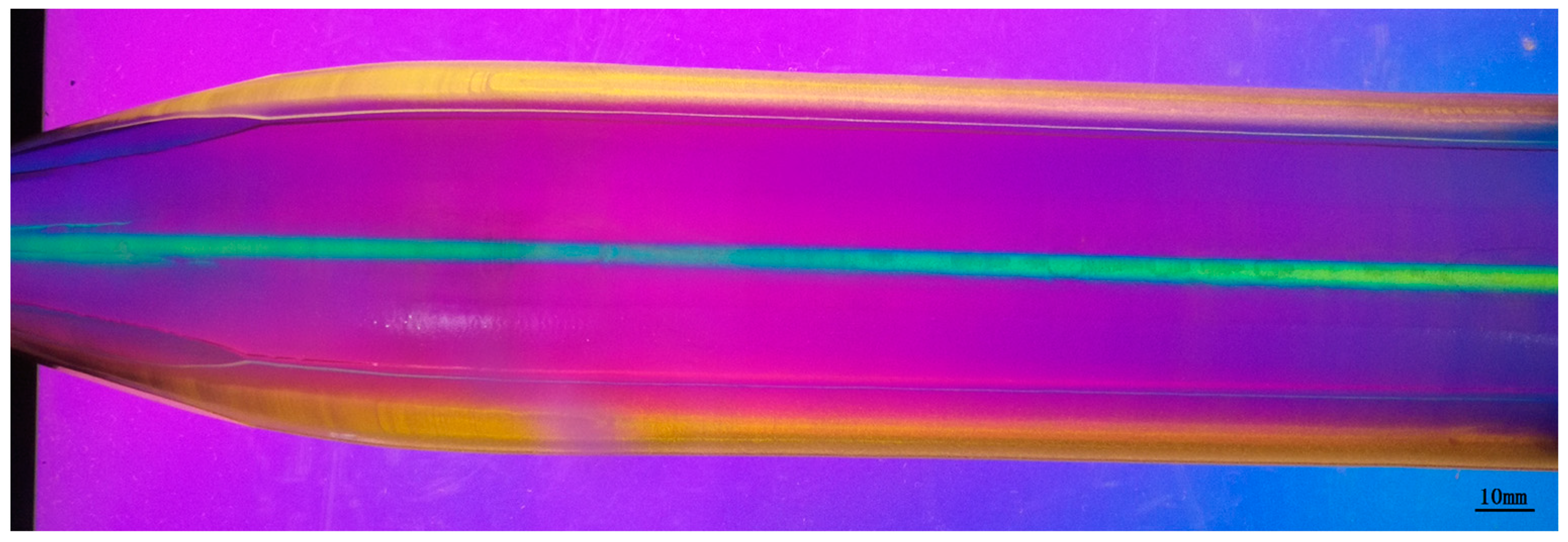
3.3. Central and Lateral Cores of the Crystal

A large Nd:YAG crystal produced using the medium-frequency induction CZ method usually grows with a convex interface, inevitably resulting in central and lateral cores defects in the crystal. The presence of central and lateral cores severely compromises the optical uniformity of the crystal. Figure 5a shows the stress region generated by central and lateral cores of the poor-quality crystal, which was grown experimentally, as observed using the stress meter, and the central core is shown by the arrow. Figure 5b shows the crystal growth interface, where the lateral core (arrow) has a large petal shape. Figure 5c shows the large central and lateral cores of the crystal observed under red parallel light. The size of the central and lateral cores are important considerations in selecting a crystal. The reduction and elimination of central and lateral cores of the crystal are critical problems that need to be addressed to grow large Nd:YAG crystals.

3.3.1. Reducing the Central Core of the Crystal

The solid–liquid interface of a crystal growing in a melt is typically rough. When the rough surface is parallel to a low-index surface of the crystal, a facet appears. The low-index surfaces of the Nd:YAG crystal are primarily {211} and {110} facets, and the position and number of facets that appear are primarily determined by the orientation of the seed crystal and the shape of the solid–liquid interface. Generally, Nd:YAG crystals are grown with a convex interface using seed crystals oriented in the <111> direction, three {211} facets with an angle of 19°28′, and with the <111> direction at the top of the interface [15]. The crystal facet, known as the central core of the crystal, has the highest concentration of impurities and stresses, as shown by the yellow area and central core position of the crystal in Figure 5a. Previous studies [16] have demonstrated that the Nd3+ concentration of the central core is 20% higher than that outside the central core.
Assuming that the solid–liquid interface of the crystal growth is a rough surface, where σ represents the free energy in any direction and θ represents the angle between the {211} facet and the curved, rough surface, the following expression is satisfied:
σ   c o s   θ = σ { 211 } ,
where σ{211} is the surface free energy of the {211} facet [17]. The {211} facet only appears after the {111} facet has become stable. Increasing the convexity of the solid–liquid interface or overheating the melt reduces the faceted area or hinders the formation of facets.
Considering the above analysis in conjunction with the actual growth characteristics of large Nd:YAG crystals, we appropriately increased the temperature gradient across the solid–liquid interface by adjusting the heat dissipation of the thermal insulation system during the crystal growth experiment. The growth of the crystal’s central core was considerably reduced by continuously adjusting the rotation speed over the different growth stages of the crystal. Figure 6 shows the core distribution (blue area) of a 65 mm diameter Nd:YAG crystal observed using the stress meter. The crystal was grown along the <111> direction by adjusting the temperature field and using a crystal rotation rate of 14–11 rpm during the cylindrical growth stage. The area of the crystal central core area is effectively reduced, and stress is generated over an extremely small area.

3.3.2. Reducing the Lateral Core of the Crystal

The formation of a lateral core in the Nd:YAG crystal grown using the CZ method with a convex interface is primarily attributed to the growth of the {110} facet. When the {110} facet is tangent to the solid–liquid interface, small crystal facets are formed on the growth interface. The growth of these small crystal facets results in the formation of a lateral core in the crystal.
Brice [18] derived an expression for the crystal facet size considering the difference between the growth mechanisms of singular and non-singular planes and corresponding kinetic laws.
b 2 = 2 R Δ T / G ,
where G is the temperature gradient across the solid–liquid interface, ∆T is the undercooling of the interface, and R is the radius of curvature of the interface. Equation (5) shows that the area of the lateral core of the crystal can be reduced by decreasing R and ∆T and increasing G.
Considering the growth characteristics of large Nd:YAG crystals, we chose to reduce the area of the small surface by adjusting G at the solid–liquid interface, which is the most effective and feasible way of reducing the lateral core. The results of many experiments showed that the central and lateral cores of Nd:YAG crystals were reduced by increasing the temperature gradient above the liquid level to ~16 °C/mm. Figure 7a,b shows the lateral core of the crystal observed under red parallel light before and after changing the temperature gradient, respectively. The areas of the central and lateral cores of the crystal before the improvement were relatively large, whereas after the improvement, the areas were considerably reduced.

4. Conclusions

We performed several experiments to study the growth interface of large Nd:YAG crystals. The solid–liquid interface shape associated with crystal growth was controlled via the interaction between natural and forced convection. The balance between natural and forced convection in the melt was achieved due to the combined effect of the interaction of the crystal pulling speed, crystal rotation speed, and thermal field surrounding the crystal. The convexity of the growth interface can be increased by increasing the temperature gradient of the solid–liquid interface or decreasing the crystal rotation rate. The more convex the growth interface is, the smaller the central and lateral cores of the crystal are. During the crystal growth process, the growth interface was controlled by slowly reducing the crystal rotation rate and increasing the temperature gradient across the solid–liquid interface. Interface inversion generally occurred during the shoulder stage and late stage of the cylinder phase of crystal growth. The occurrence of interface inversion was directly related to the temperature field, process parameters, and diameter of the grown crystal. The interface inversion of large Nd:YAG crystals was successfully eliminated by designing a suitable temperature environment for crystal growth, continuously reducing the crystal rotation rate, and ensuring a suitable diameter for the growing crystal. The areas of the central and lateral cores of the crystal were considerably reduced by increasing the temperature gradient across the solid–liquid interface and adjusting the rotation speed at different growth stages of the crystal. The experimental results show that under the conditions of a crystal rotation rate of 16–10 rpm and a temperature gradient of 15–18 °C/mm, high-quality Nd:YAG crystals with a diameter of 65 mm can be grown, with smaller central and lateral cores, and the interface inversion phenomenon is avoided.

Author Contributions

Conceptualization, J.Q. and Y.Z.; methodology, J.H., J.Q. and Y.Z.; validation, J.H., J.Q. and G.K.; formal analysis, J.Q. and J.L.; writing—original draft preparation, J.Q.; writing—review and editing, J.H. and J.Q.; visualization, G.K. All authors have read and agreed to the published version of the manuscript.

Funding

This work was supported by the Guangzhou Science & Technology Project of Guangzhou (Grant No. 202102080585).

Data Availability Statement

Data will be made available on request.

Acknowledgments

The authors would like to thank the Guangzhou Semiconductor Material Academy of Photoelectric Materials Research and Development Center for their technical assistance during crystal growth.

Conflicts of Interest

The authors declare no conflict of interest.

References

  1. Ambar, C.; Vishwakarma, S.C.; Vachhani, D.M.; Singh, R.; Misra, P.; Jain, R.K. Study and development of 22 kW peak power fiber coupled short pulse Nd:YAG laser for cleaning applications. Opt. Laser Eng. 2014, 62, 69–79. [Google Scholar]
  2. Quan, J.L.; Yang, X.; Yang, M.M.; Ma, D.C.; Huang, J.Q.; Zhu, Y.Z.; Wang, B. Study on growth techniques and macro defects of large-size Nd:YAG laser crystal. J. Cryst. Growth 2018, 483, 200–205. [Google Scholar] [CrossRef]
  3. Yadegari, M.; Asadian, M.; Saeedi, H.; Khodaei, Y.; Mirzaei, N. Formation of gaseous cavity defect during growth of Nd:YAG single crystals. J. Cryst. Growth 2013, 367, 57–61. [Google Scholar] [CrossRef]
  4. Yang, H.M.; Feng, G.Y.; Zhou, S.H. Thermal effects in high-power Nd:YAG disk-type solid state. Opt. Laser Technol. 2011, 43, 1006–1015. [Google Scholar] [CrossRef]
  5. Katsurayama, M.; Anzai, Y.; Sugiyama, A.; Kokie, M.; Kato, Y. Growth of neodymium doped Y3Al5O12 single crystals by double crucible method. J. Cryst. Growth 2001, 229, 193–198. [Google Scholar] [CrossRef]
  6. Eakins, D.E.; Held, M.; Norton, M.G.; Bahr, D.F. A study of fracture and defects in single crystal YAG. J. Cryst. Growth 2004, 267, 502–509. [Google Scholar] [CrossRef]
  7. Saeedi, H.; Yadegari, M.; Enayati, S.; Asadian, M.; Shojaee, M.; Khodaei, Y.; Mirzaei, N.; Asl, I.M. Thermal shocks influence on the growth process and optical quality of Nd:YAG crystal. J. Cryst. Growth 2013, 363, 171–175. [Google Scholar] [CrossRef]
  8. Cao, Y.H. Shape of the solid-liquid interface during CZ growth of YAG and doped YAG crystal. J. Synth Cryst. 1998, 27, 47–51. [Google Scholar]
  9. Lan, C.W.; Tu, C.Y. Three-dimensional simulation of facet formation and the coupled heat flow and segregation in Bridgman growth of oxide crystals. J. Cryst. Growth 2001, 233, 523–536. [Google Scholar] [CrossRef]
  10. Banerjee, J.; Muralidhar, K. Simulation of transport processes during Czochralski growth of YAG crystals. J. Cryst. Growth 2006, 286, 350–364. [Google Scholar] [CrossRef]
  11. Asadian, M.; Seyedein, S.H.; Aboutalebi, M.R.; Maroosi, A. Optimization of the parameters affecting the shape and position of crystal-melt interface in YAG single crystal growth. J. Cryst. Growth 2009, 311, 342–348. [Google Scholar] [CrossRef]
  12. Kostić, S.; Lazarević, Z.Ž.; Radojević, V.; Milutinović, A.; Romcević, M.; Romcević, N.Ž.; Valcić, A. Study of structural and optical properties of YAG and Nd:YAG single crystals. Mater. Res. Bull. 2015, 63, 80–87. [Google Scholar] [CrossRef]
  13. Xu, X.Z.; Chen, X.J.; Jiang, T.Y.; Tian, H.Q.; Li, Q.Y.; Li, Y.M.; Yin, J.M.; Zhang, M. Study on improving the concentration homogeneity of Nd3+ ions in Nd:YAG crystals. J. Synth. Cryst. 1998, 27, 233–236. [Google Scholar]
  14. Carruthers, J.R. Flow transitions and interface shapes in the Czochralski growth of oxide crystals. J. Cryst. Growth 1976, 36, 212–214. [Google Scholar] [CrossRef]
  15. Jiang, T.Y.; Chen, X.J.; Xu, X.Z.; Tian, H.Q.; Zhang, H.; Han, S.Y.; Li, Y.M.; Yin, J.M. Growth technology of fine quality large size Nd:YAG crystals. J. Synth. Cryst. 1996, 25, 205–211. [Google Scholar]
  16. Belt, R.F.; Puttbach, R.C.; Lepore, D.A. Crystal growth and perfection of large Nd:YAG single crystal. J. Cryst. Growth 1972, 13, 268–271. [Google Scholar] [CrossRef]
  17. Linares, R.C. Growth of garnet laser crystals. Solid State Commun. 1964, 2, 229. [Google Scholar] [CrossRef]
  18. Brice, J.C. Study on crystal cracking. J. Cryst. Growth 1977, 42, 427–430. [Google Scholar] [CrossRef]
Figure 1. Central and lateral cores distribution of neodymium-doped yttrium aluminum garnet (Nd:YAG) crystals grown at different rotation rates; (a) the rotation rates are 16–13 rpm and (b) 18–15 rpm.
Crystals 13 00970 g001
Figure 2. Growth interface of Nd:YAG crystals prepared at the same crystal growth speeds and different temperatures; (a) the temperature gradients across the crucible mouth of ~1 °C/mm and (b) 15 °C/mm.
Crystals 13 00970 g002
Figure 3. Interface inversion of the crystal during the late stage of the shoulder growth.
Crystals 13 00970 g003
Figure 4. Interface inversion of the crystal growth during the late stage of the equal-diameter phase.
Crystals 13 00970 g004
Figure 5. (a) Stress region generated by the central and lateral cores of the crystal observed using a stress meter. (b) Large petal-shaped central core of the crystal. (c) Large central and lateral cores of the crystal observed under red parallel light.
Crystals 13 00970 g005
Figure 6. Distribution of the central core of the Nd:YAG crystal grown in the <111> direction after adjusting the temperature field, as observed by an orthogonal polarizing system.
Crystals 13 00970 g006
Figure 7. Lateral core of an Nd:YAG crystal observed under red parallel light (a) before and (b) after improving the temperature gradient.
Crystals 13 00970 g007
Disclaimer/Publisher’s Note: The statements, opinions and data contained in all publications are solely those of the individual author(s) and contributor(s) and not of MDPI and/or the editor(s). MDPI and/or the editor(s) disclaim responsibility for any injury to people or property resulting from any ideas, methods, instructions or products referred to in the content.

