1. Introduction
Steering and directing the path of propagating waves in a desired manner are essential for utilizing or dissipating wave energy and have received considerable attention from the wave research community [
1,
2,
3,
4,
5,
6,
7,
8,
9,
10,
11,
12]. A kind of classical wave, controlling water wave energy is important, but very challenging, for energy extraction and costal protection in practical ocean engineering. Following the progress of photonics and phononics, water surface waves have recently been manipulated by interacting with periodic structures such as cylinder arrays, rippled bottoms, or surface scatters [
13,
14,
15,
16,
17,
18,
19,
20,
21,
22]. To steer and guide water waves through interaction with a periodic configuration, one can either manipulate water wave propagation by creating a line defect based on the concept of bandgap defect modes [
23] or by forming a focusing lens through a homogenization of the periodic medium [
18,
24]. However, similarly to their classical bulk wave counterparts, it is almost impossible to guide surface water waves in any desired manner without relying on arrangements of walls or a large numbers of unit cells and their homogeneous modification at the level of the entire periodic system.
Metamaterials are artificial unit cell systems with dimensions much smaller than the wavelength of the propagating waves, which may provide solutions for water waveguiding without the introduction of a large number of unit cells while releasing the dimensional dependence of traditional periodic structures. Electromagnetic, acoustic, or elastic metamaterials have aroused wide interest recently, including superlensing [
25], cloaking [
26,
27], and evanescent wave tuning [
28,
29], to name a few. Among different designs of metamaterials, subwavelength waveguiding has been realized based on Fano-type interference in a medium arranged with Helmholtz resonators (HRs) (e.g., arrays of soda cans in [
3]). As a planar counterpart of metamaterials, a plasmonic Fano-resonance metasurface can also be applied in colorimetric sensing [
30]. In addition, waveguiding for imaging at a subwavelength scale has also been achieved based on Fabry–Pérot (FP resonance) in a holey-structured medium [
29]. Compared with a defect mode-based waveguide (e.g., [
31]), the two abovementioned metamaterial waveguiding techniques indicate that water waves might also be steered and guided in a way mainly dependent on wave coupling with resonators. However, bulk wave metamaterials cannot be directly applied to manipulate water waves since water wave energy, unlike classical bulk waves in metamaterials with complicated spatial geometries, is mostly confined to the surface. Thus, to control multi-band water wave propagation on the surface with only a few unit cells, a proper structure has to be identified to inherit the concept of multi-band low-frequency waveguiding utilized in bulk wave metamaterials. The achievement of water waveguiding can pave a potential way for steering and directing water wave energy for energy extraction and costal protection in ocean engineering.
In this work, despite not being as efficient as topological waveguides, we numerically and experimentally demonstrate that by arranging HR-based unit cells in a water wave metamaterial in the configuration of a T shape, it is possible to directionally shape and guide water waves as if flowing through an open-space virtual channel. The proposed metamaterial consists of two rows and columns of resonators arranged as a T-shaped configuration. These resonators are disconnected split cubes made of copper configured by concurrent fan-shaped cavities with a designed symmetry. Inside the metamaterial, a T-shaped path with three inlets is formed via these copper split tubes. By creating the geometrical symmetry within the fan-shaped HRs cavities and introducing local disorder in the metamaterial, we numerically and experimentally show that the proposed T-shaped metamaterial serves as a waveguide at specific working frequencies. This work is of significance in two aspects. One is that we show that Fano-type interference and Fabry–Pérot resonance mechanisms can be simultaneously applied to achieve multi-band low-frequency water waveguiding. The other more important aspect is that the design of the proposed T-shaped metamaterial is rather simple and can be easily fabricated (e.g., metal or polymer materials) to achieve distinct flow paths (e.g., symmetrical and asymmetrical transmission) of water wave energy and even realize potential unidirectional propagations that might be promising for constructing water wave circulators in the future.
2. Unit Cells and the Corresponding Band Structure and Transmission Characteristics
The unit cell of our metamaterial is a water wave version of a Helmholtz resonator [
32,
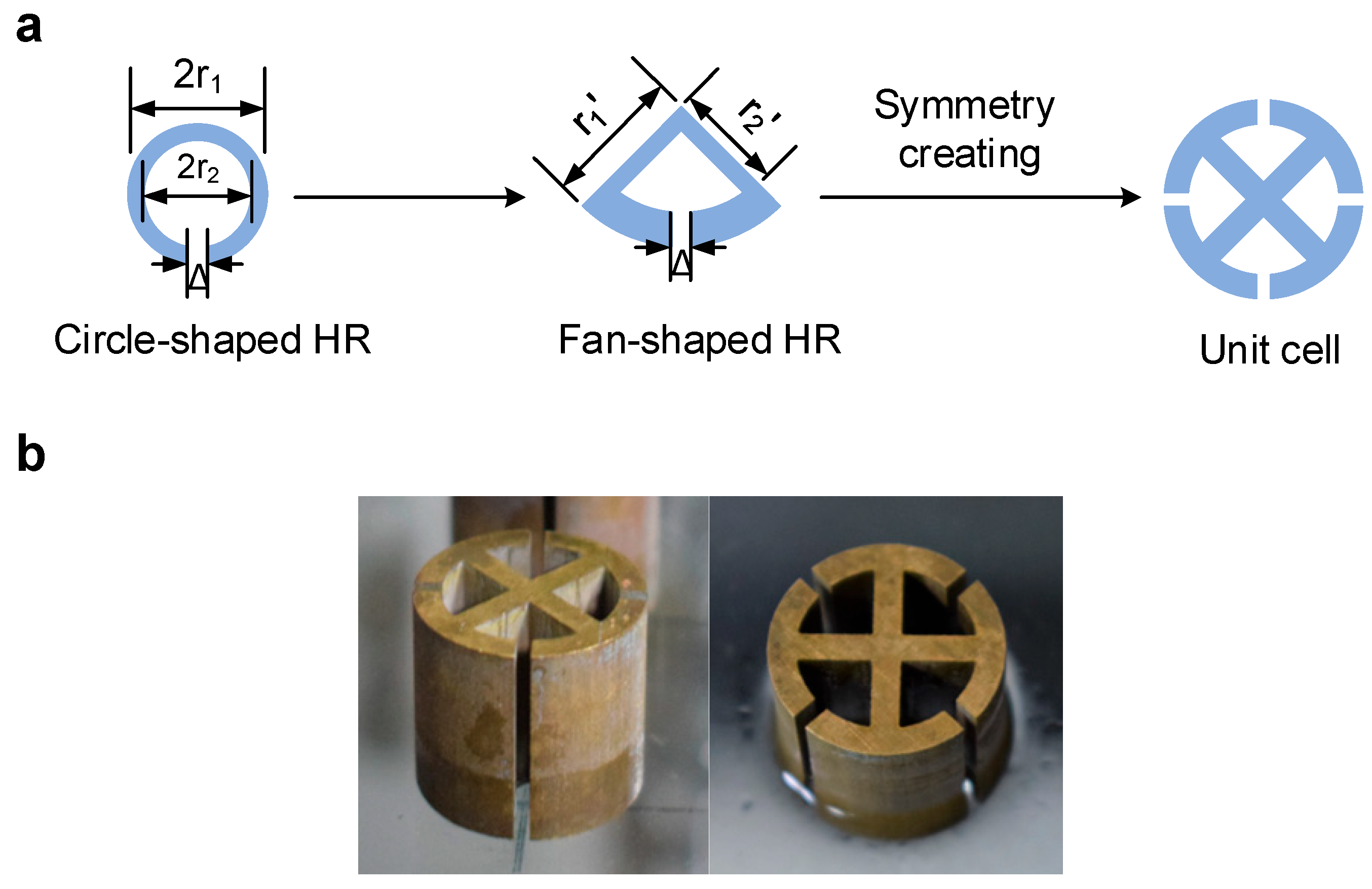
33]. As shown in
Figure 1a, the configuration of the unit cell is a concurrent single-degree-of-freedom (SDOF) split tube, where each sub-cavity has a fan-shaped configuration that can geometrically fit the other three components to form a circle-shaped unit cell. The geometric parameters of the fan-shaped split tubes are determined according to the design of C-shaped split tubes, whose resonance characteristics have been analytically obtained [
32,
33]. The reference C-shaped split tube is characterized by three main parameters—the slit width Δ, the outer radius
, and the internal radius
—which correspond to a resonant wave number
. We set Δ = 1 mm,
= 4 mm, and
= 3 mm and obtain a resonant frequency
= 4.4 Hz. The dimensions of the fan-shape split tubes are then designed to match the resonance frequencies of the referenced C-shaped split tubes. The equivalent fan-shaped split tube has an internal radius
=
= 8 mm, an outer radius
=
= 6 mm, and a slit width Δ = 1 mm, respectively. The unit cell can be easily fabricated using metal (e.g., a copper split tube shown in
Figure 1b) or polymer materials.
Here, we conducted the simulation of the propagation of water waves using COMSOL Multiphysics based on the fact that the vertical displacement of water wave
satisfies the two-dimensional Helmholtz equation [
18,
34] which reads as
where we consider the dispersion relationship
in which
h is the water depth.
We first consider the band structure of a two-dimensional water wave metamaterial constructed by the concurrent split-tube unit cell (see the inset in
Figure 2), also calculated by a finite element solver (COMSOL Multiphysics). As shown in
Figure 2a, along the
direction, we see a positive dispersion band above the local resonance frequency, which spans a smaller frequency range of about 0.12 Hz (5.14 Hz–5.26 Hz, marked with green ▲). This passband and the resonant frequency are all contained in a wide bandgap with a range from 4.53 Hz to 6.47 Hz (between the blue dash lines). Note that with the unit cells, water wave propagation in this band remains rather isotropic (comparing the dispersion curves along the
and
directions). Interestingly, there is another negative dispersive band (less than 4.5 Hz), which will be studied in our following work.
Next the effective refraction index with respect to the effective depth and effective gravitational acceleration is considered to reveal the physical nature of the passbands. In the long-wavelength range [
18,
21], the shallow water wave equation can be viewed as a homogeneous liquid with a linear dispersion given by
where
is the effective wave number of water waves. The refraction index can be expressed as
The real part of the effective refractive index is shown in
Figure 2b. Both the effective depth and effective gravity must simultaneously maintain a positive or negative value to ensure a real effective refractive index. We note that the effective refractive index corresponding to frequencies larger than 5.25 Hz may need correction, since the long-wavelength assumption may not be satisfied anymore. However, it still can be a useful reference to explain important observations in the following sections.
To gain a deeper insight into the band structure, we further simulate the propagation of the water wave field in a one-dimensional array of the split-tube unit cells with corresponding wave patterns at different frequencies, as shown in
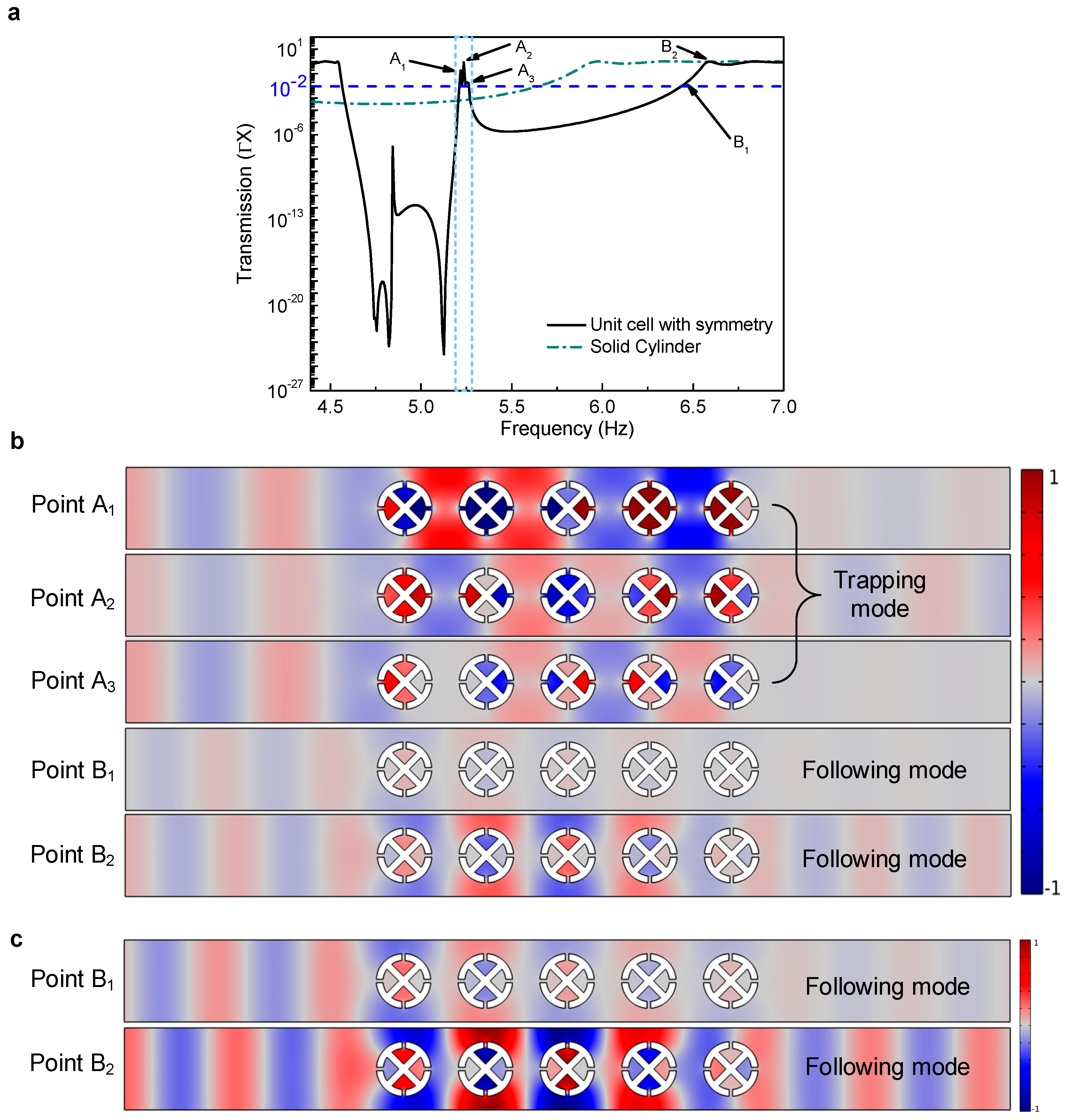
Figure 3. In
Figure 3a, the transmission coefficient is calculated based on the ratio (
Ttr/Ti)
2, where
Ttr is the amplitude of the absorbed waves obtained from the line average of the amplitude distribution at the right boundary of the rectangle computation domain and
Ti is the amplitude of incident waves that is set to 1 at the left boundary of the computation domain. Note that the amplitude of the wave field at the left boundary of the domain is chosen as unity to avoid the influence of the reflected waves caused by the unit cells. A wide and deep bandgap is generated by the one-dimensional array of unit cells, compared to the Bragg scattering bandgap generated by the solid cylinders. It is found that there is an asymmetric resonant peak centered at 5.17 Hz in the transmission, which we attribute it to the zero group-velocity mode at 5.13 Hz that is observed in the band structure in
Figure 2a. This asymmetric peak can be more clearly observed when the global lattice constant
a increases to 26 or 28 mm (see discussions in
Section 3). Note that a similar asymmetric peak in the transmission has been found in the elastic metamaterial [
35] and acoustic metamaterials [
3,
36,
37] recently, which is caused by Fano-like interference between the incoming waves and the reflecting waves that radiate from the local resonators [
3]. The present one-dimensional split-tube array also reveals a similar Fano-type interference phenomenon characterized by the abovementioned asymmetric profile in the transmission. In particular, the Fano-type interference phenomenon leads to a narrow positive dispersion band in the transmission, also known as the “transparency window” [
38,
39], which corresponds to the narrow band in the band structure. In this narrow window, the group velocity is extremely slow (i.e., a slow flow of water wave energy), which is indicated by the flat band structure in
Figure 2a. Note that the narrow window in the transmission has also been explained as the coupling between locally resonant and Bragg bandgap in other work [
38]. It can be observed that the bandgap in the transmission is wider and deeper than that caused solely by the Bragg scattering in the array of solid cylinders. Thus, it is not a typical bandgap generated from the local resonance of the unit cell. Following the explanation on the formation of the bandgap in many locally resonant metamaterials, here a hybridization bandgap [
40] is used to address the coupling and interaction between the resonance scatters and their surrounding propagating waves. The band near the upper bandgap edge (around 6.5 Hz in
Figure 2a) indicates water wave propagation is influenced by wavelength-scale multiple scattering [
28]. On the contrary, the local high transmission in the positive dispersion band (
Figure 2a) is induced by constructive Fano-type interference. Since in our design, all the unit cells are identical with the same local resonance frequency, the presence of the positive dispersion band indicates that a resonant defect [
3,
41] (detuning the resonant frequency of one unit cell from that of the rest ones) operating at this frequency range is not necessarily required to support a passband in the bandgap, which occurs in their acoustic counterparts [
3]. The positive refractive index at this band (
Figure 2b), where the group and phase velocity have the same direction, also proves the dominance of the Fano-type interference. We note that the existence of the Fano-type interference-induced positive dispersion can be robust to a local disorder of the unit cells that generally leads to different multiple scattering conditions at wavelength scale, which will be discussed in the next section.
As shown in
Figure 3b, we now study the propagation of water waves passing through a finite unit cell array at the frequencies connected to three peak values inside the narrow passband (5.14–5.26 Hz) and those near the upper edge of the bandgap (around 6.46~6.58 Hz), corresponding to points A
1, A
2, A
3, B
1, and B
2 that marked in
Figure 3a, respectively. Note that the red and blue regions in the field represent the vertical displacement of the water waves. These wave fields are normalized by the maximum vertical displacement of the water waves corresponding to the point A
2. The differences of the wave propagation at these frequencies lie in the propagation pattern of waves and the efficiency of the transmission. Two distinct transmitting patterns are classified when the operating wavelength varies from 61.3 mm to 32.8 mm (corresponding to a frequency range from 4.14 Hz to 6.58 Hz). At points A
1, A
2, and A
3, the water wave pattern appears to be shaped as being trapped between adjacent round unit cells, and thus this pattern is classified as a “trapping mode”. The trapped pattern results from the constructive Fano-type interference at operating frequencies in the positive dispersion band, and the two face-to-face fan-shaped cavities in the unit cell function as an open-space water waveguide. We can observe that the four fan-shaped cavities within the unit cell impose forces and serve as boundaries to trap water wave energy. At points A
1, A
2, and A
3, it is observed that the change in interference conditions caused by the variation in wavelength of the incident waves, leads to the variation of the wave amplitude and wavelength inside the one-dimensional array. Note that at point A
3, the constructive interference brings a lower peak value compared to that of points A
1 and A
2, but still maintains the abovementioned “trapping mode” by the modulation effect of the one-dimensional array. It is worth mentioning that arbitrary frequencies inside the positive dispersive band should share similar wave propagation patterns as those at points A
1, A
2, and A
3 since their propagation modes are controlled by the constructive interference effect. The differences between them lie in transmission peak values and the propagating pattern of water waves. Overall, the unit cells trap the water waves in the band of frequencies within the narrow transparency window. For points B
1 and B
2 in
Figure 3b,c (normalized by the maximum vertical displacement of the water waves in the field corresponding to point B
2) water waves can also propagate along the unit cell array, but contrary to the trapping mode at A
1, A
2, and A
3, the water wave pattern appears to be shaped at the same location of the unit cell and the overall water waves at both frequencies behave as if they can transmit along the array without being disturbed by the presence of the unit cells. Thus, we classify this mode as a “following mode”. In particular, at point B
2, the unit cell array maintains the amplitude and phase of the incident wave (wave length
32.8 mm) even after the water wave has left the array, while at point B
1 the transmission
33.7 mm is relatively weak, similar to that at point A
3. Here, Fabry–Pérot resonance (FP resonance), well known for optical cavities, is given to explain the transmission characteristics at points B
1 and B
2, based on the observed relatively perfect transmission and no delayed phase of the water wave in this closed channel with the present one-dimensional unit cell array. The following reasons are given for using FP resonance to account for the transmission: (i) the resonance condition (i.e., an integer multiple of half-wave wavelength) is approximately satisfied due to the length of whole one-dimensional array
; (ii) the negative refractive index close to −1 shown in
Figure 2b at these frequencies provides proper strong reflection points for water waves to maintain their phase (see
Supplementary Note Figure S1 for more details on the relation between negative refraction index and the maintenance of the phase of water wave). Note that for point B
1, the phase of the water wave at this frequency (6.47 Hz) is better maintained inside the array compared to that of B
2, since the corresponding negative refractive index is a little bit closer to −1 (see
Figure 2b), while for point B
2 the water wave at this frequency (6.58 Hz) satisfies the FP resonance condition better where the one-dimensional array length is equal to 6.8 times of
and a higher transmission is thus guaranteed. This closed channel thus acts as an “optical path” for those water waves at frequencies (including points B
1 and B
2.) near the upper edge of the bandgap. Note that the FP resonance has recently been applied to design a water wave concentrator [
42]. Based on these observations, we find the cavity-type configuration and its symmetry in the unit cell play a crucial role in forming the above trapping and following modes. The behaviors observed in the unit cell also indicate that such a configuration can possibly be used to shape, guide, or focus water waves with only a few unit cells.
3. Manipulating Band Properties via Introducing a Local Disorder
The effective refractive index, corresponding to a band of frequencies within the transmission window of the bandgap, is closely related to the effective depth
and effective gravitational acceleration
. By adjusting the filling ratio
, the two effective parameters can be tuned and the properties of the passband in the bandgap as well as the band-edge state can be manipulated [
18,
32]. We now study the effect of the periodicity (lattice constant
) and disorder (local unit-cell orientation variation) on the transmission characteristics of the one-dimensional unit cell array. The two considered variables can effectively influence the interior position relation among adjacent unit cells and then the filling ratio
. Thus, “the trapping mode” and “the following mode” can be manipulated, since the variation of
may change the Fano-type interference condition or the Fabry–Pérot resonance condition, corresponding to the positive dispersive passband and band-edge state, respectively. Using these transmission behaviors, in the next section we design a water wave metamaterial to shape and guide the wave propagation based on the “trapping mode” at points A
1, A
2, and A
3 (see
Figure 3a) (with an introduction of a fixed local orientation perturbation) and the “following mode” at point B
1 and B
2 (with an introduction of a fixed local spacing variation).
As shown in
Figure 3a and
Figure 4a, the passband in the bandgap almost vanishes if the lattice constant satisfies
> 24 mm when the influence of the Fano-type interference in the array is weakened. Far away from the local resonant frequency, the positive effective gravitational acceleration
is produced inside the positive dispersive passband, which can also be observed in [
33] within similar frequencies (around 5.25 Hz) range, where their HR-based unit cell possesses the same local resonant frequency (
= 4.4 Hz) with the unit cell in the present work. As mentioned in
Section 2, the effective depth
and effective gravitational acceleration
must remain the same sign to ensure a real effective refractive index. Thus, the effective depth inside the positive dispersive passband must also be positive, which here is due to the Bragg resonance (
close to
2a) based on the water wavelength-scale multiple scattering. Note that our simulation results indicate that the effective refractive index inside the positive dispersive passband should be around 0
1.1 (seen in
Figure 2b), corresponding to the filling ratio (
) in the current configuration. This result is also confirmed by the relevant discussion in [
18,
32]. An alternative explanation may also be given to describe the source of the positive dispersive band, which is the interplay between the local resonance and Bragg resonance. This has already been observed as the transparency in the relevant bandgap of the acoustic metamaterials in [
38] and also serves as a water wave analogue of electromagnetically induced transparency (EIT) by quantum interference [
39]. This positive passband transparency occurs when the local resonant frequency is close to the Bragg one. Note that this explanation on the source of the positive dispersive band does not contradict the one we describe in
Section 2 (Fano-type interference). They are different theories that attempt to explain the physical origin of the narrow dispersive passband. The close frequencies between the local resonance and Bragg one should also be necessary conditions for the occurrence of constructive Fano-type interference to ensure the existence of the narrow positive dispersive passband. Furthermore, the bandwidth of the bandgap increases as the lattice constant
reduces. This is due to the fact that a decreasing lattice constant
causes a phase shift in the resonance-induced reflecting wave and the corresponding passband is generated by the corresponding constructive interferences with the incoming wave. For the frequency region near the upper edge of the bandgap (
Figure 4a, around 6–7 Hz), the transmission is significantly affected by the variation in the lattice constant, since these short waves are more sensitive to the change in wavelength-scale multiple scattering conditions.
We further investigate the effect of the orientation in some unit cells on the passband in
Figure 3a. As shown in
Figure 4b, the fourth and the fifth (not illustrated) unit cell in the array is rotated clockwise to introduce local disorder. It is shown in
Figure 4b that the passband shifts toward the high-frequency region with a slight reduction in the transmission in magnitude as the rotation angle of the fourth unit cell increases (note that 75° corresponds to 15°). This slightly reduced transmission indicates/suggests that the flow and accordingly the direction (i.e., the rectilinear path along the rectangle channel) of the water wave energy is influenced. In other words, water wave energy does not perfectly flow along the one-dimensional metamaterial in this scenario. We note that the local disorder here actually changes the lattice constant in that region, but does not cause the disappearance of the window. This is a different aspect compared to the global change of the lattice constant.
Similarly, the upper edge of the passband continues to shift to a relatively higher frequency when the fifth unit cell is also rotated clockwise, as shown in
Figure 4b. Near the upper edge of the bandgap, we observe a fluctuation in the water wave transmission, but water waves can still maintain the working frequencies. Thus, the local rotated unit cells will not affect the water wave propagation in this frequency range at which the propagating pattern is supported by the Fabry–Pérot resonance. The relations of the bandwidth between the global lattice constant and the local rotation angles of the fourth and fifth unit cells are further plotted in
Figure 4c,d, respectively. Unlike the lattice constant, the bandwidth does not linearly vary with respect to the rotation angle. Due to the symmetry of the fourth and fifth unit cells, the transmission should maintain the same result for
and
, and this fact is observed in
Figure 4d.
4. T-Shaped Waveguide with a Local Disorder
In
Section 3, it is observed that with a proper global lattice constant, a local change in the orientation of the unit cell in the one-dimensional array can lead to a slight lowering and shift of the transmission peak inside the transmission window, which means the propagation of the water wave energy on the initial path (along the rectangle channel) might be controlled. However, the wave energy is still trapped between the unit cells for the band of frequencies in the transmission window. The trapped water wave might be able to be released from the non-rectilinear path. Thus, it is rational to imagine that water waves might change their propagation directions if alternative paths (i.e., not the initial rectilinear path) are available for them. In this case, the flow of the water wave energy can be manipulated and even designed. Inspired by this idea, we now show that the two propagating modes mentioned above can be used to manipulate water waves to propagate along different paths. We utilize the property of the positive dispersion passband and the band-edge state to design a T-shaped water waveguide, consisting of only two arrays of unit cell with a lattice constant
= 24 mm, as shown in
Figure 5a. This specific lattice constant is chosen to match the previous given filling ratio criteria. The two unit cells at the intersection (“1” and “1′” as shown in the dashed box in
Figure 5a) are symmetrically rotated by 45° to serve as a local disorder. Note that a T-shaped water waveguide owns three inlets (or outlets), which is an ideal metamaterial to show that water waves with certain frequencies are able to propagate along different paths within the metamaterial.
As shown in
Figure 5b,c, when a point source is located near the left inlet of the T-shaped waveguide, water waves at some frequency ranges in the passband propagate uniformly between the two unit cell arrays as if being confined in a virtual channel in the open space. This open-space virtual channel is formed by the previous defined “trapping mode” between the adjacent four unit cells. With the designed T-configuration and the two symmetrically oriented unit cells, three distinct water wave propagation patterns are obtained: bending, asymmetrical splitting, and symmetrical splitting, as shown in
Figure 5b–d. When the point source is at the left inlet, the water wave is bent from the horizontal to vertical branch after passing the intersection at
Hz (
Figure 5b). In addition, the water wave is asymmetrically split into the horizontal and vertical branches at
= 5.33 Hz (
Figure 5c). When the point source is located at the bottom inlet as shown in
Figure 5d, the water wave is symmetrically split into the two horizontal virtual channels. The results in
Figure 5 indicate that it only calls for two arrays of unit cells in open space to guide water waves in the passband. In addition to the shaped propagating pattern, we note that each propagation mode remains rather isotropic, which has been addressed in the discussions for
Figure 2a.
The change in the propagation direction shown in
Figure 5 can be inspired by the transmission property of the one-dimensional metamaterial array shown in
Figure 3a (a disorder-free array) and
Figure 4b (with a local orientation-dependent disorder), in which the transmission window is slightly tuned to the high-frequency region with the presence of the locally rotated resonators (see the green line in
Figure 4b). As shown in
Figure 4b, the local disorder at certain unit cells changes the width of the transmission window as well as some peak values at certain frequencies in the window. However, it does not influence the existence of the “trapping mode” of water waves. This means that the water wave energy is still trapped between the unit cells with lower peaks in the modified window, which might be able to be released from other paths different from the initial one. Note that the propagation of the water waves is rather isotropic in the transmission window, as shown by the dispersion curves along the
and
directions in
Figure 2a. This indicates that in the transmission window water waves have a potential ability to propagate along other directions with the same “trapping mode” in other similar windows. Here, the rotation of the unit cell provides this possibility, that is, changing the propagation direction of the water waves by imposing “force” with different directions on the waves. Thus, a
bending of water waves in
Figure 5b for the frequencies in the window is possible by rotating the unit cells at the intersection by an angle of 45°, in which the rotating unit cell acts as a mirror with an equal incidence and reflection angle (i.e., 45°). However, it is observed in
Figure 4b that for certain frequencies in the window, there are still some water waves that can maintain a relatively large transmission peak to some extent under the influence of the rotated unit cells, which means a part of wave energy still flows along the initial rectilinear path. Thus, the asymmetrical transmission in
Figure 5c is also observed. In other words, one can determine if the energy flow of the water wave at a specific frequency in the window changes its rectilinear propagation by the observation of its transmission peak in the one-dimensional array with the rotated unit cells. A small transmission peak in the transmission window means a large portion of wave energy flows into non-rectilinear paths, while a relatively large peak means a part of wave energy can still flow along the initial direction (i.e., along rectilinear path). A similar principle also applies for the identification of the symmetrical transmission in
Figure 5d, where the wave source is located near the inlet of the vertical branch. Thus, different water wave-propagating paths depend on the transmission in their initial rectilinear propagation direction. The origin of these different transmitting patterns for water waves is the Fano-type interference mechanism that induces the transmission window characterized by the narrow band and the extremely high transmission. Different rotation angles of unit cells modify the Fano-type interference conditions inside the arrays, indicated by the change in the vertical displacement of the water wave near the intersection of the metamaterial, which redistributes the lower and high peaks in the initial transmission window and eventually leads to different degrees of the variation on the propagation direction of the water waves. Thus, the key to steering and guiding water waves with the “trapping mode” is to use different orientations to control the direction of forces imposed by the rotated unit cells. In the present work, our unit cell consists of four identical fan-shaped cavities. To steer water waves toward more directions, it is necessary to construct more fan-shaped cavities in the same unit cell.
The numerical results indicate that the water wave can be either totally (
= 44.9 mm,
Figure 5b) or partially (
= 44.5 mm,
Figure 5c) bent towards the vertical virtual channel. Despite such an inevitable change for the propagation directions at the “trapping mode”, the “following mode” passing after the T-intersection can possibly still be realized, as shown in
Figure 5e, when the working frequency is near the upper edge of the bandgap. The metamaterial fails to bend the water wave at the “following mode” between the vertical face-to-face resonators since the rotated resonators “1” and “1′” are symmetric in geometry without the variation in global lattice constant and basically do not influence the Fabry–Pérot resonance condition to a large extent. We note that the effective refractive index of the T-shaped waveguide in this mode (close to −1 as shown in
Figure 2b) ensures a rectilinear propagation, which makes the proposed T-shaped waveguide a perfect lens to focus water waves at these frequencies (see
Supplementary Note Figure S1). The band-edge “following mode” allows water wave propagation along the arrangement direction of the unit cell array based on the reflecting effect at the outlet of each unit cell in a virtual channel. Similarly, water waveguiding under the “following mode” is also realized as that under the “trapping mode” without any solid boundaries. This may be of great importance in ocean engineering, since it is more practical to use a few large-scale cylinders to realize Fabry–Pérot resonance compared with the assistance of solid boundaries [
42]. Note that a part of the water wave energy flow may leak from the virtual channel into surrounding field under both modes, compared to the relatively perfect transmission in the one-dimensional metamaterial with solid walls. as shown in
Figure 3a,b. Compared to the “following mode”, the “trapping mode” shows larger dependence on the number of cavities and thus a clearer leakage is present. The loss of water wave energy when flowing along the virtual channel will be weakened when the global lattice constant becomes smaller, which means that the T-shaped configuration is more compact and the virtual channel tends to evolve into one with solid walls.
Next, we experimentally validate the four classified possible patterns (bending, asymmetrical splitting, symmetrical splitting, and rectilinear transmission). As shown in
Figure 6a,b, a T-shaped water wave metamaterial waveguide consisting of 22 split tubes is set up in a water tank (see Methods for detailed description) on a vibration isolation table. Each concurrent split tube is made of copper with an outer radius
= 8 mm and an inner radius
= 6 mm. The height of the resonator is 15 mm and the slit width is Δ = 1 mm. The lattice constant is 24 mm. To avoid high viscosity and large surface tension, a liquid (CFC-113) is utilized to replace the water. The depth of the liquid (CFC-113) is kept at 8 mm during the experiments.
A point source is located 4 mm away from the inlet of the waveguide. The ripple generator has a frequency resolution of 0.1 Hz and can operate at frequency ranges from 1 to 50 Hz. Ten rod-type laser pointers are put 2 cm above the top surface of the resonators at prescribed locations to measure the low-frequency vertical vibration on the water surface with the help of a digital image correlation (DIC) technique. An aluminum plate (not shown in
Figure 6a) is put 7 cm above the top of the resonators on which holes are drilled to support the laser pointers. The laser spots are reflected to a projection screen and the widest laser spot has a dimension of ~2 mm. The two resonators at the intersection of the T-shaped waveguide are rotated clockwise and anticlockwise, respectively, with an angle of 45° to serve as a local disorder (see the inset in
Figure 6b). When validating the “trapping mode”, each laser pointer is located above the center of our adjacent resonators, and the point-wise laser spots are shown in
Figure 6c. On the other hand, when validating the “following mode”, each laser pointer is shifted to be located above the center of two face-to-face resonators and the laser spots become a line shape due to a larger surface tension from the walls of the unit cells, as shown in
Figure 6d. For the DIC technique, a digital camera (Nikon D3300, Nikon Corporation, Tokyo, Japan) is used to record the vibration of each laser spot for approximately 30 s at each frequency in 1920 × 1080 pixels at 50 frames per second (see
Supplementary Movies M1–M4). Then, a MATLAB code is developed to extract the recorded frames for the DIC technique to calculate the amplitudes to demonstrate the propagating patterns.
The measuring vibration amplitudes of the four patterns, normalized by that at the first detection location close to the inlet, are shown in
Figure 7a–d. The corresponding 10 detection locations are also illustrated in the insets of
Figure 7a–d for a clear observation of the water shaping effect.
Figure 7a shows the first bending pattern (at 5.1 Hz), where the amplitudes at the vertical branch (the points 8, 9, and 10) are larger than those at the branch in the original propagation direction (the points 5, 6, and 7). At 5.3 Hz (
Figure 7b), comparing the amplitude at point 5 with that at point 8, the water wave is split to the two channels (horizontal and vertical ones) after passing the T-intersection (asymmetrical splitting). The dissipation of the water wave can be seen from the results at points 5 to 7 along the horizontal channel and points 8 to 10 along the vertical channel. When the point source is located close to the inlet of the vertical branch at 5.2 Hz as shown in
Figure 7c, the amplitudes at the points 5 to 7 are almost comparable to those at points 8 to 10. Thus, the amplitude results indicate that the water wave is equally split to the two horizontal branches of the T-shaped waveguide (symmetrical splitting). Finally, at 6.6 Hz (corresponding to
Figure 6d for line-shape laser spots and
Figure 7d), the amplitude at point 5 is larger than that at point 8, which indicates that the water wave mainly maintains the rectilinear propagation with a larger dissipation. The above four identified frequencies and patterns agree well with the numerical predictions.
Although the liquid CFC-113 has low viscosity and surface tension compared to water, the amplitudes of the vibration after the water wave passing through the unit cell are still significantly dissipated. The surface tension distorts the laser spots and magnifies the DIC measurement errors for the “following mode” at 6.6 Hz between the face-to-face resonators (see
Supplementary Note Figure S2). In addition, in the experiments, the wave fields outside the waveguide inevitably affect those inside the virtual channels, and this leads to larger vibration amplitudes at certain points (such as the measuring results at points 9 and 10 in
Figure 7a). It should be noted that the low-frequency resolution of the wave source (0.1 Hz) also limits the accuracy of the experimentally identified patterns.


