Article

Study on the Surface Generation Mechanism during Ultra-Precision Parallel Grinding of SiC Ceramics

1
State Key Laboratory for Manufacturing Systems Engineering, Xi’an Jiaotong University, 28 Xianning West Road, Xi’an 710049, China
2
Research Institute of Xi’an Jiaotong University, Hangzhou 311200, China
3
State Key Laboratory of Ultra-Precision Machining Technology, Department of Industrial and Systems Engineering, The Hong Kong Polytechnic University, Hung Hom, Kowloon, Hong Kong 999077, China
*
Authors to whom correspondence should be addressed.
Crystals 2023, 13(4), 646; https://doi.org/10.3390/cryst13040646
Submission received: 19 February 2023 / Revised: 24 March 2023 / Accepted: 2 April 2023 / Published: 9 April 2023
(This article belongs to the Special Issue Processing Technology of Brittle Crystal Materials)

Abstract

:
Silicon carbide (SiC) is a typical, difficult-to-machine material that has been widely used in the fabrication of optical elements and structural and heat-resistant materials. Parallel grinding has been frequently adopted to produce a high-quality surface finish. Surface generation is a vital issue for assessing surface quality, and extensive modeling has been developed. However, most of the models were based on a disc wheel with a cylindrical surface, whereas the surface topography generation based on an arc-shaped tool has been paid relatively little attention. In this study, a new theoretical model for surface generation in ultra-precision parallel grinding has been established by considering the arc-shaped effect, synchronous vibration of the wheel, and cutting profile interference in the tool feed direction. Finally, the ground surface generation mechanism and grinding ductility were analyzed in the grinding of SiC ceramics. The results showed that the spiral and straight-line mode vibration patterns were the main feature of the machined surface, and its continuity was mainly affected by the phase shift. Furthermore, for the in-phase shift condition, the grinding ductility was more significant than for the out-of-phase shift due to the continuously decreasing relative linear speed between the wheel and workpiece.

1. Introduction

SiC is an advanced engineered ceramic widely used in optics (hot-press mold and telescope mirror) [1,2,3], electronics [4], and biomedical fields [5] due to its excellent unique properties, such as extreme hardness, good wear resistance, high intensity, high durability, and excellent thermal stability [6,7,8]. Despite the salient potential properties of SiC ceramics, it is a typical hard-to-machine material and has poor machinability due to lower fracture toughness and extreme hardness. At present, ultra-precision grinding (a root-mean-square figure accuracy of <0.1 μm and a surface roughness Sq of < 0.01 μm) is the predominant cutting technique to produce a high-quality surface in the machining of hard and brittle materials [9,10,11]. In ultra-precision grinding, the machined surface quality principally depends on the motion precision and machining method of the CNC grinding machine. A microremoval process of target materials and the fabrication of curved surface shapes can be realized by precisely controlling the movement path of the grinding wheel [12,13,14]. According to the relative motion relationship between the grinding wheel spindle and the workpiece rotation spindle, the methods can be divided into the parallel grinding method [15], transverse grinding method [16], and oblique grinding method [17]. Oblique axis grinding can be further divided into spherical grinding wheel grinding, point grinding, normal grinding, and generating grinding according to the contact state and motion mode between the grinding wheel and workpiece [18]. Even with the same processing parameters, different grinding methods will produce completely different surface morphologies. This is mainly because grinding follows the “copy” nature, and different grinding surface morphologies are formed due to the different trajectories of abrasive particle movement and the different degrees and modes of mutual interference in different paths. Parallel grinding is the most commonly used complex surface machining method. The workpiece spindle and grinding wheel spindle are controlled by the xz slides to machine various rotary symmetric surfaces. In this method, the cutting direction of the grinding wheel is consistent with the rotation direction of the workpiece on the cutting zone between the tool and the workpiece, so the grinding surface is formed along the radial direction of the spiral trajectory. In this grinding mode, a diamond arc grinding wheel or spherical grinding wheel is generally adopted.
To achieve a “damage free” surface, extensive research has been carried out on surface generation mechanisms in the grinding of SiC ceramics. There are two types of surface generation mechanisms in grinding: brittle fracture or ductile mode [19]. To obtain a good surface finish, the ductile grinding mode needs to be the dominant mechanism [20,21]. Therefore, much research has been conducted on the influence of physical parameters on the ductile-to-brittle transition. The nanoindentation test [22,23,24] and single abrasive scratch [25,26,27,28] experiment were widely employed in the study of crack damage and the surface formation mechanism in the grinding of SiC ceramics. The primary goal of these studies was to determine the threshold for the ductile-to-brittle transition in order to control the grinding load below the critical value, so as to achieve crack-free machining with a good surface finish. This research provided the quantitative relationship between the load and crack size; however, the surface generation resulted from the combined effect of the wheel geometry and tool dynamic characteristics has received little attention [29,30,31]. In grinding, surface generation is a function of the wheel shape and trajectory path and hence is affected by the tool motion error and tool geometry. In fact, the wheel spindle vibration oriented primarily perpendicular to the workpiece surface is the sensitive direction of the surface topography generation, which has a great impact on the machining accuracy and surface roughness [32,33,34,35]. Chen et al. [36] investigated the influence of wheel vibration on surface roughness, and a theoretical kinematic model for surface generation was established by simplifying the wheel into a circular section. Cao et al. [37] developed a topography generation model by considering unbalanced wheel vibration, and the influence of vibration amplitude, grit size, and machining parameters on surface roughness and surface microwaviness were investigated. However, the waviness generation was considered as a motion copy of the tool oscillation locus and ignored the influence of the wheel shape. Since a 2D cross section of the wheel (cylinder grinding wheel) was picked to simulate the surface generation, it cannot be used to evaluate the impact of vibration phase shift on surface topography generation. Chen et al. [38] investigated the influence of grinding parameters on surface generation and found that the phase shift had a dominant impact on both surface roughness and waviness features. Based on the authors’ experimental results, the distribution of cutting points in parallel grinding was studied, and a waviness pattern model was developed. The results showed that the phase shift had a remarkable effect on waviness geometry evolution, and a strategy was proposed to suppress the surface waviness [39]. Pan et al. [40] proposed a new method to improve the ground surface quality and uniformity in the grinding of a complex optical surface with a non-integer rotation speed ratio (phase shift effect).
However, most of the previous modeling work for ground surface generation was based on a disc wheel with a cylindrical surface, and the cutting profile interference in the circumferential direction of the workpiece was considered. In fact, the surface generation was more sensitive in the cross-feed direction when a grinding wheel with an arc cutting edge was adopted. The surface generation process is governed by many factors, such as wheel vibration, material properties, wheel geometry, and phase shift, which are essential in achieving surface quality control and grinding process optimization. In order to predict the surface generation more accurately, in this study, a new model for surface generation in parallel grinding was developed by comprehensively taking into account the effect of phase shift, tool vibration, and wheel cutting nose radius. The phase shift effect involved in the surface generation in the grinding of SiC ceramics was analyzed.

2. Modeling of Surface Generation in Ultra-Precision Grinding Considering Tool Vibration

In parallel grinding, a diamond grinding wheel with a circular arc on the cutting edge profile is mostly adopted. The cutting direction of the grinding wheel is tangentially parallel to the rotation direction of the workpiece, but the direction of their linear velocities are opposite to each other (reverse grinding). Figure 1 is a typical schematic diagram of parallel grinding. When the wheel rotates, it moves toward the center of the workpiece at a constant feed rate. Since the rotation speed and feed rate of the workpiece remain constant, the distance the grinding wheel moves toward the center of the workpiece is constant for each cycle the workpiece rotates; thus the tool path of parallel grinding on the workpiece surface is a spiral. In the grinding process, the linear velocity of the workpiece is different at different cutting points of the grinding wheel, and the volume of the material removed when the grinding wheel completes one circle is proportional to the radial position of the grinding point on the workpiece surface. Therefore, the relative motion error of the grinding wheel, geometrical shape of the grinding wheel, and machining parameters will have an important influence on the ground surface topography generation. In ultra-precision parallel grinding, the workpiece spindle is vertical to the grinding wheel spindle, and the wheel performs a linear feed motion from the edge of the workpiece to the rotating center along a spiral path to realize the material removal process, as shown in Figure 1.
In parallel grinding, an extremely tiny depth of cut and a low rotational speed of the workpiece spindle combined with a high-speed grinding wheel are generally selected to achieve the microvolume of material removal. In this process, the grinding wheel cutting profile is constantly fed horizontally along the wheel axis direction (ignoring abrasive grains) to generate the micromachined topography. As shown in Figure 2, the spindle speed of the grinding wheel (ω2) and the tool feed speed (vf) together generate the tool interference in the adjacent cutting path interval, in which the surface residual profile (radial direction) forms. The angular position of the grinding wheel cutting point (θi) on the workpiece is equal to the angle of rotation of the workpiece. The grinding operation parameters can determine the relative cutting position and tool path of the grinding wheel with respect to the workpiece, which can affect the surface topography generation of the workpiece. Therefore, the machining parameters, the geometry of the grinding wheel cutting profile, and the relative position of and error between the grinding wheel and the workpiece have a great influence on the formation of the ground surface.
The ground surface generation strongly depends on the relative travel trajectory of the cutting tool, which is determined by the operation parameters, tool geometry, and movement errors. The most significant of these is the relative motion error of the grinding wheel in the normal direction, which causes the varying engaged depth of the tool. This leads to the increment in surface residual height and degrades the surface roughness. In the case of non-constant grinding conditions due to the motion errors acting on the grinding wheel, the resultant machined surface is a function of the tool cutting edge geometry and the relative movement of the tool.
In grinding, the relative motion of the wheel is the result of the superposition of the motion of each axis, which transfers characteristics of the wheel cutting profile to the part surface and determines the final machined surface generation. Therefore, the geometric modeling of surface topography generation can be calculated according to the motion process of each axis. Figure 2 schematically shows the motions of the wheel and workpiece in ultra-precision parallel grinding, which include the rotation of the workpiece and grinding wheel as well as the linear movement of the machine table along the feed direction (x axis). However, the vibration with the same frequency as the wheel rotation is the dominant mode of tool vibration, which is responsible for the ground surface profile variation and degrades the surface quality.
According to the geometric relation of the relative motion of the grinding wheel with respect to the workpiece, the coordinates of the circular arc contour of the grinding wheel in each radial position of the workpiece and the intersection point of the adjacent circular arc contour were obtained, with which the residual surface profile can be calculated to reconstruct the finished surface. The coordinate system X1-Y1-Z1 was employed to calculate the workpiece surface profile generation. The discrete workpiece surface can be established in the radical and circumferential directions, in which it is divided into a certain number of segments along the circumferential and radical directions of the workpiece with an equal angle interval ( Δ θ ) and tool path interval ( S ), respectively. The number of cutting positions on the workpiece surface can be expressed as:
N r = 2 π Δ θ N c = R s S ,   S = v 1 v f
where Δ θ —the discrete angle value (rad);
R s —the radius of the workpiece (mm);
S —the feed rate (mm/r);
v 1 —the rotation speed of the workpiece (r/min);
v f —the feed speed (mm/min).
In parallel grinding, the workpiece spindle rotates with a slow angular velocity, and the grinding wheel slowly moves towards the center of the workpiece transversely with a constant feed speed, whereby the tool trajectory is a spiral in the XY plane. In order to accurately predict the surface topography of the workpiece under the condition of tool vibration, it is first necessary to evaluate the motion trajectory of the cutting profile in the workpiece coordinate system. In polar coordinates, the movement trajectory of the wheel in discrete form can be calculated as follows:
θ w ( i ) = i Δ θ + j 2 π ,   i = 0 , 1 , 2 , N r 1 R w ( i ) = R s Δ θ 2 π i + j S , j = 0 , 1 , 2 , N c 1 Z w ( i ) = A sin ( ω 2 Δ θ i + 2 π j ω 1 + φ )
where A —the vibration amplitude of the grinding wheel (mm);
ω 1 —the angular speed of the workpiece (rad/min);
ω 2 —the angular speed of the wheel (rad/min);
φ —phase angle (rad).
In ultra-precision grinding, the residual height generation on the workpiece surface is tracked by the wheel location movement. The discrete tool path model represents a series of wheel loci. For a given pair of tool positions, there is an intersection between the two cutting profiles of the grinding wheel due to the fine feed rate in ultra-precision parallel grinding. In order to calculate the intersected segment, a cutting plane is defined, which includes the lowest engagement point of the wheel and leaves the deepest scratch on the machined surface, as shown in Figure 3. Therefore, the machined surface can be obtained by calculating the intersection of two adjacent cutting profiles.
There is an arc edge on the cutting profile of the grinding wheel, which moves in a single path of approximately a circle, which is expressed as:
( y i S ) 2 + z + Z w ( i ) 2 = r 2
In the process of ground surface generation, the tool cutting profile of the grinding wheel moves along the spiral tool path, and the tool–workpiece interference in the feed direction envelopes the final machined surface. In actual grinding, the wheel axis changes due to the existence of vibration, which in turn results in a variable residual profile on the machined surface. Therefore, the surface topography of a certain section of processing, the influence of the previous feed, and the subsequent feed should be fully considered. The specific consideration method is as follows:
[ y ( i 1 ) S ] 2 + z + A sin [ ω 2 Δ θ i + 2 π ( j 1 ) ω 1 + φ ] 2 = r 2 ( y i S ) 2 + z + A sin ( ω 2 Δ θ i + 2 π j ω 1 + φ ) 2 = r 2 [ y ( i + 1 ) S ] 2 + z + A sin [ ω 2 Δ θ i + 2 π ( j + 1 ) ω 1 + φ ] 2 = r 2
The scallop height is calculated at a cutting point by comparing the height value of neighboring tool cutting profiles and selecting the minimum value, which is responsible for the final ground surface generation. The surface residual height of each cutting point can be expressed as:
z e = min z i , j 1 ( ρ , θ ) , z i , j ( ρ , θ ) , z i , j + 1 ( ρ , θ )
The experiments were performed on a four-axis grinding machine (Moore Nanotech 450UPL). The ultra-precision grinding machine consists of two linear guides (x axis and z axis) and two rotation spindles (workpiece spindle and wheel spindle), as shown in Figure 4. The samples were mounted on an aluminum fixture, which was placed on the vacuum chuck of the workpiece spindle. Before grinding, dynamic balancing of the two spindles was carried out to make the radial runout less than 10 nm. In order to obtain the amplitude of the wheel vibration, a laser displacement sensor with high resolution was employed. A resin-bonded diamond grinding wheel was selected with a 1500# mesh size. The parallel grinding tests were performed on reaction-sintered SiC to investigate surface generation and verify the ground surface model. Before the test, all the samples were ground to obtain a relatively flat surface to reduce the effect of tool wear, and we then preformed the wheel dressing operation before each experiment. A Taylor Hobson roughness profiler (Form TalySurf PGI 1240; measuring error: 0.8 nm vertical resolution) was used to measure the machined surface after the tests.
Table 1 shows the grinding conditions and operation parameters adopted for the machining tests. A diamond arc-shaped wheel was chosen with a 0.5 mm nose radius. The influence of phase shift with respect to wheel synchronous vibration can have a significant effect on surface topography generation in ultra-precision parallel grinding, which can be selected by adjusting the grinding wheel speed.

3. Experiment Results and Discussion

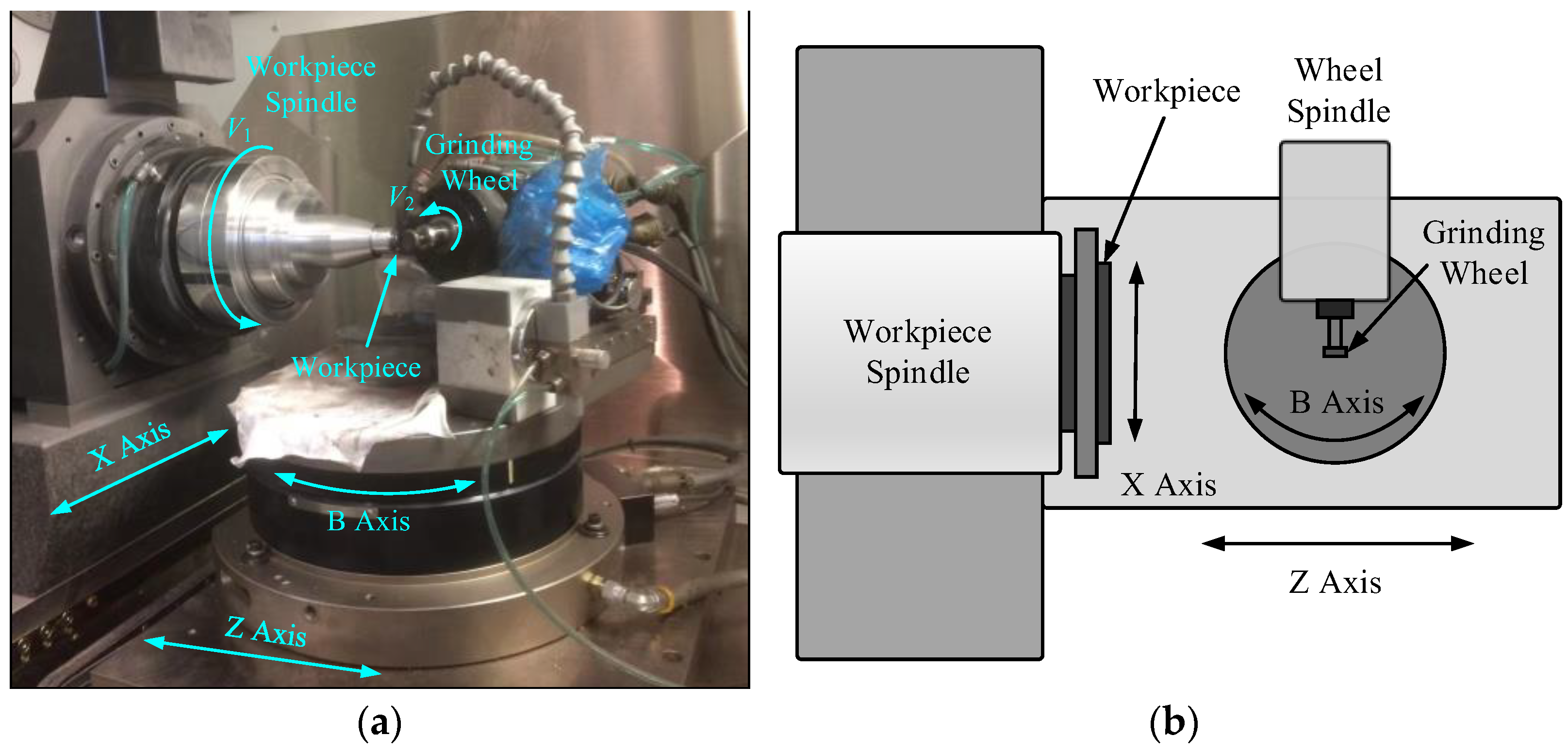
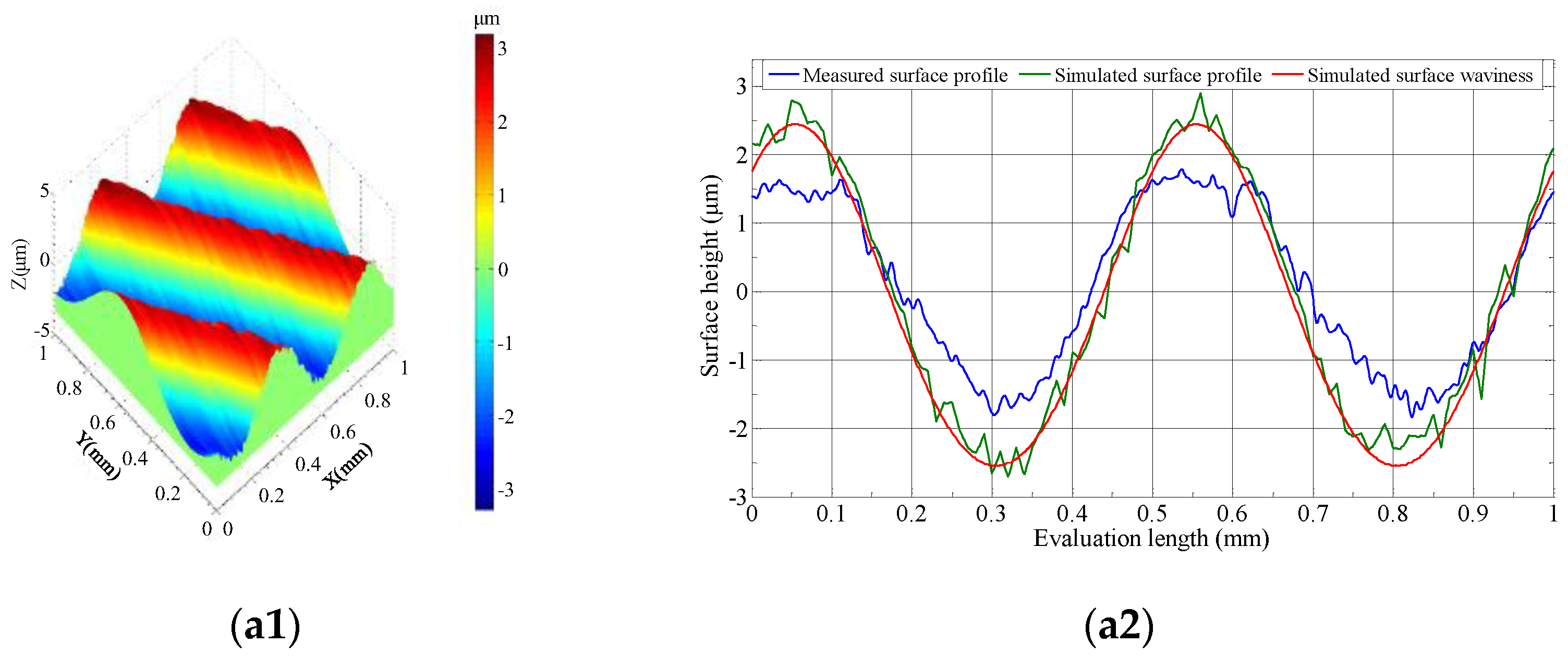
3.1. Experimental Results and Validations

To verify the surface generation model, a series of grinding tests under different phase shifts were conducted. A laser displacement sensor was used to measure the wheel spindle error motion. The amplitude of the tool vibration was obtained by recording 5 values under variable phase shifts, and it was found that the average amplitude value was about 2.5 μm in all ranges of wheel speeds. The cross section profiles of the ground surface were measured under different phase shifts: Figure 5(a1,a2) phase = 0, Figure 6(a1,a2) phase = 0.1, Figure 6(b1,b2) phase = 0.3, Figure 6(c1,c2) phase = 0.5, Figure 6 (d1,d2) phase = 0.7, and Figure 6(e1,e2) phase = 0.9. Figure 5 shows a comparison between the simulated surface profile and the measured results, in which the surface profile height and period are highly consistent. The machined surface had different waviness patterns and evolved continuously with the processing cycles, and it finally developed a series of microwaviness marks around the rotation center of the workpiece. In the process of machining, microwaviness stripes were formed on the workpiece surface by the grinding wheel vibration, which was affected by the grinding wheel speed, feed speed, and workpiece speed, resulting in the formation of surface stripes with different geometric patterns.
The continuous waviness structure formed when the phase shift was 0, 0.1, and 0.9, as shown in Figure 5(a1) and Figure 6(a1,e1); however, a discontinuously structured wave pattern was generated when the phase shift was 0.3, 0.5, and 0.7, as shown in Figure 6(b1,c1,d1). This indicates that the phase shift has a significant effect on the surface finish, in which the wheel speed only has a minor change (for example, 0.385% for the wheel speed change from 39,000 rpm to 39,150 rpm in Figure 5(a2) and Figure 6(a2), respectively). The theoretical surface profile height in Figure 5(a2) shows a maximum at the phase shift of 0 (out-of-phase shift), in which the wheel speed is equal to an integer multiple of the workpiece speed (V1/V2 = 39,000/1500 = 26). With the further increase in phase shift (in-phase shift), however, the machined surface profile height presents a dramatic decrease (height amplitude decreases from 2.5μm to 0.5μm), and the speed ratio is not an integer number (such as V1/V2 = 39,150/1500 = 26.1 in Figure 6(a2)). With the development of the phase shift, the discontinuity of the waviness pattern occurs at the phase shift of 0.3, 0.5, and 0.7, as shown in Figure 6(b1,c1,d1). In this case, there is a larger difference in the tool depth of cut at adjacent tool tracks in the presence of grinding wheel vibration. As the phase shift increases from 0 to 0.5, the cross section profile height of the machined surface decreases; however, the profile height increases when the phase shift further increases from 0.7 to 0.9 (the phase shift is close to 1). This shows that the phase shift can contribute to reducing the surface scallop height and improving the machined surface quality. These results showed that the theoretical model could accurately predict the resulting surface generation, including the surface waviness and profile. In comparison to the conventional modeling approaches that take into account the surface generation in the wheel cutting direction, the proposed modeling algorithm, by considering the cutting profile interference in the tool feed direction, is more accurate in predicting the surface waviness profile generation in the parallel grinding operation, in which the effects of the phase shift, wheel vibration, and wheel cutting nose on surface generation are comprehensively calculated.
The model is capable of estimating the ground surface generation precisely and determining the role of the phase shift in the ultra-precision parallel grinding as well. However, the deviation from the actual experiments was attributed to the wheel wear in the grinding of the SiC ceramics.
From the results above, it is found that the surface waviness is the main characteristic of machined surface generation, which is caused by the synchronous vibration of the grinding wheel. The phase shift plays a key role in governing the surface waviness profile, in which the phase shift farther away from an integer is more conducive to generating denser waviness and a lower surface profile height.

3.2. Experimental Analysis of Surface Generation

The machined surface images of the samples under different phase conditions (out of phase and in phase) are shown in Figure 7. It can be clearly observed that a spiral mark formed on the ground surface, and the mark period changed with the phase shift development which is caused by the vibration of the grinding wheel. In the central area, the vibration mark evolved into a straight-line mode, which acted along the tangent orientation of a circular section (uncut area). The straight-line pattern for the vibration marks were attributed to the gradually decreasing linear velocity when the cutting point between the tool and workpiece moved from the outer regime to the centers of the rotation for the part spindle. We found a more ductile area for the ground surface generation in the center area in comparison with the edge regime for parallel grinding of SiC. This shows a higher grinding ductility in the center area, which is caused by the gradually decreasing chip size under constant decreasing liner cutting speed. Furthermore, the ground surface condition improved with the appearance of the phase shift both for the edge and center regions, in which a less fractured area was formed due to smaller chips generated by a higher degree of wheel cutter trajectory interference, as shown in Figure 7a,b. This shows that the phase shift is an important factor both for the evolution of vibration marks and grinding ductility. The main reason for this is the increase in interference on adjacent cutting paths under in-phase shift conditions, which results in the decrease in surface residual height. This indicates that the radial interference of adjacent grinding paths has a significant effect on the machined surface quality and cannot be ignored. The phase shift alters the relative grinding wheel position between neighboring tool paths with respect to the workpiece, which directly influences the relative depth of cut for abrasive grains distributed on the wheel and in turn effects the ductility for material removal. The phase shift effect can enhance the interference of adjacent abrasive grains’ cutting paths and help to reduce the surface residual height, which can significantly improve the surface quality of grinding.

4. Conclusions

In this study, the surface generation mechanism in ultra-precision parallel grinding of RB-SiC ceramics was investigated, and a model for surface generation was established by considering wheel synchronous vibration to calculate the evolution mechanism of vibration marks on the ground surface. The surface generation model was established by considering multiple factors including the arc-shaped effect, tool synchronous vibration, and cutting profile interference in the tool feed direction, in which the effect of the phase shift on the surface topography generation was validated. The main conclusions are as follows:
(1)
Wheel synchronous vibration has a dominant impact on surface generation, in which slight changes in the rotational speed of the grinding wheel leads to great waviness in pattern variation. This is due to the huge difference in depth of cut for tool cutting profiles which interferes with neighboring cutting edges in the feed direction.
(2)
The phase shift has a great influence on the continuity of waviness generation; the phase (phase = 0, 0.1, and 0.9) closer to an integer tends to generate continuous waviness, whereas the phase (phase = 0.3 and 0.5) farther away from an integer tends to generate discontinuous waviness patterns. This is caused by the relative changes in the depth of cut between adjacent tool paths.
(3)
In parallel grinding, the surface generation by way of the ductile mode is more susceptible to appear in the central location of the ground surface due to the decreasing linear velocity. The phase shift has an effect on grinding ductility; for in phase, a ductile removal surface is more likely formed.
There is a good agreement between the novel, developed model and the real experimental results. The theoretical model and experimental results for surface generation provide an effective method to control surface quality and suppress the surface microwaviness in the parallel grinding of ceramic materials.

Author Contributions

Conceptualization, S.C. and C.F.C.; methodology, S.C.; software, T.L.; validation, S.C., S.Y. and D.D.; formal analysis, Z.J.; investigation, S.C.; resources, L.-t.H. and D.D.; data curation, S.C.; writing—original draft preparation, S.C.; writing—review and editing, S.C.; visualization, S.C.; supervision, S.Y. and C.F.C.; project administration, Z.J.; funding acquisition, S.C. All authors have read and agreed to the published version of the manuscript.

Funding

This work was supported by the Major Program of the National Natural Science Foundation of China (52293404), Major Program of the National Natural Science Foundation of China (52293405), National Natural Science Foundation of China (52105481), National Natural Science Foundation of China (52005397), Natural Science Foundation of Zhejiang Province (LQ21E050010), National Key R&D Program of China “strategic science and technology innovation cooperation” project (SQ2022YFE020500), and China Postdoctoral Science Foundation (2019M663681). The authors would like to thank the Key Research and Development Program of Shaanxi Province (2021ZDLGY12-06) and the Fundamental Research Funds for the Central Universities (XZD012022068) of China for their financial support.

Data Availability Statement

Not applicable.

Conflicts of Interest

The authors declare no conflict of interest.

References

  1. Beaucamp, A.; Simon, P.; Charlton, P.; King, C.; Matsubara, A.; Wegener, K. Brittle-ductile transition in shape adaptive grinding (SAG) of SiC aspheric optics. Int. J. Mach. Tool Manufact. 2017, 115, 29–37. [Google Scholar] [CrossRef]
  2. Jalluri, T.D.P.V.; Gouda, G.M.; Dey, A.; Rudraswamy, B.; Sriram, K.V. Development and characterization of silicon dioxide clad silicon carbide optics for terrestrial and space applications. Ceram. Int. 2022, 48, 96–110. [Google Scholar] [CrossRef]
  3. Huang, P.; Zhang, J.Q. Strain rate effect on the ductile brittle transition in grinding hot pressed SiC ceramics. Micromachines 2020, 11, 545. [Google Scholar] [CrossRef]
  4. Tang, Z.R.; Gu, L.; Ma, H.P.; Dai, K.F.; Luo, Q.; Zhang, N.; Huang, J.Y.; Fan, J.J. Study on the surface structure of N-Doped 4H-SiC homoepitaxial layer dependence on the growth temperature and C/Si ratio deposited by CVD. Crystals 2023, 13, 193. [Google Scholar] [CrossRef]
  5. Saddow, S.E. Silicon carbide technology for advanced human healthcare applications. Micromachines 2022, 13, 346. [Google Scholar] [CrossRef]
  6. Xie, Y.L.; Deng, D.X.; Guan, P.; Huang, X.; Zhao, C.Y. Fabrication of silicon carbide microchannels by thin diamond wheel grinding. Int. J. Adv. Manuf. Technol. 2020, 111, 309–323. [Google Scholar] [CrossRef]
  7. Zhang, T.Y.; Liu, F.; Liu, Y.; Wu, C.G.; Liang, S.Y. Ultraviolet nanosecond laser-ablated groove analysis of 2.5D Cf/SiC composites. Crystals 2023, 13, 223. [Google Scholar] [CrossRef]
  8. Huang, S.Q.; Wei, Z.Z.; Rao, X.S.; Li, C.; Zhang, F.H. Optimization of processing parameters during electrical discharge diamond grinding of RB- SiC ceramics based on grey relational theory. Diam. Abras. Eng. 2021, 41, 56–62. [Google Scholar]
  9. Li, C.; Hu, Y.X.; Zhang, F.H.; Geng, Y.Q.; Meng, B.B. Molecular dynamics simulation of laser assisted grinding of GaN crystals. Int. J. Mech. Sci. 2023, 239, 107856. [Google Scholar] [CrossRef]
  10. Li, C.; Piao, Y.C.; Zhang, F.H.; Zhang, Y.; Hu, Y.X.; Wang, Y.F. Understand anisotropy dependence of damage evolution and material removal during nanoscratch of MgF2 single crystals. Int. J. Extreme Manuf. 2023, 5, 015101. [Google Scholar] [CrossRef]
  11. Li, C.; Piao, Y.C.; Meng, B.B.; Hu, Y.X.; Li, L.Q.; Zhang, F.H. Phase transition and plastic deformation mechanisms induced by self-rotating grinding of GaN single crystals. Int. J. Mach. Tool Manufact. 2022, 172, 103827. [Google Scholar] [CrossRef]
  12. Yu, S.M.; Yao, P.; Huang, C.Z.; Chu, D.K.; Zhu, H.T.; Zou, B.; Liu, H.L. On-machine precision truing of ultrathin arc-shaped diamond wheels for grinding aspherical microstructure arrays. Precis. Eng. 2022, 73, 40–50. [Google Scholar] [CrossRef]
  13. Kuriyagawa, T.; Zahmaty, M.S.S.; Syoji, K. A new grinding method for aspheric ceramic mirrors. J. Mater. Process. Technol. 1996, 62, 387–392. [Google Scholar] [CrossRef]
  14. Heike, K.F.; Taghi, T.; Bahman, A. Material removal mechanism in ultrasonic-assisted grinding of Al2O3 by single-grain scratch test. Int. J. Adv. Manuf. Technol. 2017, 91, 2949–2962. [Google Scholar]
  15. Zhong, Z.W.; Venkatesh, V.C. Recent developments in grinding of advanced materials. Int. J. Adv. Manuf. Technol. 2009, 41, 468–480. [Google Scholar] [CrossRef]
  16. Weck, M.; Hennes, N.; Schulz, A. Dynamic behaviour of cylindrical traverse grinding processes. CIRP Ann. 2001, 50, 213–216. [Google Scholar] [CrossRef]
  17. Yang, Y.C.; Wu, Y.-R.; Tsai, T.-M. An analytical method to control and predict grinding textures on modified gear tooth flanks in CNC generating gear grinding. Mech. Mach. Theory 2022, 177, 105023. [Google Scholar] [CrossRef]
  18. Chen, B.; Li, S.C.; Deng, Z.H.; Guo, B.; Zhao, Q.L. Grinding marks on ultra-precision grinding spherical and aspheric surfaces. Int. J. Precis. Eng. Manuf. Green Tech. 2017, 4, 419–429. [Google Scholar] [CrossRef]
  19. Chen, S.S.; Cheung, C.F.; Zhang, F.H. An experimental and theoretical analysis of surface generation in the ultra-precision grinding of hard and brittle materials. Int. J. Adv. Manuf. Technol. 2018, 97, 2715–2729. [Google Scholar] [CrossRef]
  20. Dong, Z.C.; Cheng, H.B. Ductile mode grinding of reaction-bonded silicon carbide mirrors. Appl. Opt. 2017, 56, 7404–7412. [Google Scholar] [CrossRef] [PubMed]
  21. Antwi, E.K.; Liu, K.; Wang, H. A review on ductile mode cutting of brittle materials. Front. Mech. Eng. 2018, 13, 251–263. [Google Scholar] [CrossRef] [Green Version]
  22. Datye, A.; Schwarz, U.D.; Lin, H.T. Fracture toughness evaluation and plastic behavior law of a single crystal silicon carbide by nanoindentation. Ceramics 2018, 1, 198–210. [Google Scholar] [CrossRef] [Green Version]
  23. Page, T.F.; Oliver, W.C.; McHargue, C.J. The deformation behavior of ceramic crystals subjected to very low load nanoindentations. J. Mater. Res. 1992, 7, 450–473. [Google Scholar] [CrossRef]
  24. Rao, X.S.; Zhang, F.H.; Luo, X.C.; Ding, F.; Cai, Y.K.; Sun, J.N.; Liu, H.T. Material removal mode and friction behaviour of RB-SiC ceramics during scratching at elevated temperatures. J. Eur. Ceram. Soc. 2019, 39, 3534–3545. [Google Scholar] [CrossRef]
  25. Shen, X.T.; Song, X.; Wang, X.C.; Sun, F.H. Grinding characteristics of CVD diamond grits in single grit grinding of SiC ceramics. Int. J. Adv. Manuf. Technol. 2021, 114, 2783–2797. [Google Scholar] [CrossRef]
  26. Zheng, Z.D.; Huang, K.; Lin, C.T.; Zhang, J.G.; Wang, K.; Sun, P.; Xu, J.F. An analytical force and energy model for ductile-brittle transition in ultra-precision grinding of brittle materials. Int. J. Mech. Sci. 2022, 220, 107107. [Google Scholar] [CrossRef]
  27. Giridhar, D.; Sakthivel, G.; Vijayaraghavan, L.; Krishnamurthy, R.; Kumar, M.S.; Gangadhar, K.; Kannan, T. Characterization of single-grit grooving process of silicon carbide ceramic using multisensory approach. Silicon 2022, 14, 5563–5575. [Google Scholar] [CrossRef]
  28. Gao, S.; Wang, H.X.; Huang, H.; Kang, R.K. Molecular simulation of the plastic deformation and crack formation in single grit grinding of 4H-SiC single crystal. Int. J. Mech. Sci. 2023, 247, 108147. [Google Scholar] [CrossRef]
  29. Tao, H.F.; Liu, Y.H.; Zhao, D.W.; Lu, X.C. Effects of wheel spindle vibration on surface formation in wafer self-rotational grinding process. Int. J. Mech. Sci. 2022, 232, 107620. [Google Scholar] [CrossRef]
  30. Czapla, T.; Fice, M.; Niestrój, R. Experimental identification of wheel-surface model parameters: Various terrain conditions. Sci. Rep. 2022, 12, 16015. [Google Scholar] [CrossRef] [PubMed]
  31. Yin, T.F.; To, S.; Du, H.H.; Zhang, G.Q. Effects of wheel spindle error motion on surface generation in grinding. Int. J. Mech. Sci. 2022, 218, 107046. [Google Scholar] [CrossRef]
  32. Chen, S.S.; Cheung, C.F.; Zhang, F.; Zhao, C.Y. Three-dimensional modelling and simulation of vibration marks on surface generation in ultra-precision grinding. Precis. Eng. 2018, 53, 221–235. [Google Scholar] [CrossRef]
  33. Huo, F.W.; Kang, R.K.; Li, Z.; Guo, D.M. Origin, modeling and suppression of grinding marks in ultra-precision grinding of silicon wafers. Int. J. Mach. Tool Manufact. 2013, 66, 54–65. [Google Scholar] [CrossRef]
  34. Inasaki, I.; Karpuschewski, B.; Lee, H.S. Grinding chatter–origin and suppression. CIRP Ann. Manuf. Technol. 2001, 50, 515–534. [Google Scholar] [CrossRef]
  35. XU, L.X.; Li, H.; Cai, X.T.; Zhou, P.X.; Chen, Y.W.; Wu, J.F. Study on surface quality in ultrasonic vibration grinding of SiC ceramics with small diameter grinding wheel. Diam. Abras. Eng. 2020, 40, 67–77. [Google Scholar]
  36. Chen, J.B.; Fang, Q.H.; Li, P. Effect of grinding wheel spindle vibration on surface roughness and subsurface damage in brittle material grinding. Int. J. Mach. Tool Manufact. 2015, 91, 12–23. [Google Scholar] [CrossRef]
  37. Cao, Y.L.; Guan, J.Y.; Li, B.; Chen, X.L.; Yang, J.X.; Gan, C.B. Modeling and simulation of grinding surface topography considering wheel vibration. Int. J. Adv. Manuf. Technol. 2013, 66, 937–945. [Google Scholar] [CrossRef]
  38. Chen, S.S.; Yang, S.M.; Cheung, C.F.; Ho, L.T.; Zhang, F.H. Suppression strategy of micro-waviness error in ultra-precision parallel grinding. Nanomanuf. Metrol. 2022, 5, 423–429. [Google Scholar] [CrossRef]
  39. Chen, S.S.; Cheung, C.F.; Zhao, C.Y.; Zhang, F.H. Simulated and measured surface roughness in high-speed grinding of silicon carbide wafers. Int. J. Adv. Manuf. Technol. 2017, 91, 719–730. [Google Scholar] [CrossRef]
  40. Pan, Y.C.; Zhao, Q.L.; Guo, B.; Chen, B.; Wang, J.H. Suppression of surface waviness error of fresnel micro-structured mold by using non-integer rotation speed ratio in parallel grinding process. Micromachines 2020, 11, 652. [Google Scholar] [CrossRef]
Figure 1. Schematic diagram of ultra-precision parallel grinding.
Crystals 13 00646 g001
Figure 2. Schematic of locus of the grinding wheel movement in ultra-precision parallel grinding (red solid line indicates tool path and blue dash line represents wheel vibration locus).
Crystals 13 00646 g002
Figure 3. Schematic diagram of surface generation modeling in grinding.
Crystals 13 00646 g003
Figure 4. Configurations of 4-axis ultra-precision grinding machine: (a) ultra-precision machine tool for grinding experiments; (b) structural layout of the grinding machine.
Crystals 13 00646 g004
Figure 5. Simulated surface and measured surface under out-of-phase shift (phase = 0): (a1) simulated surface topography; (a2) surface profile height.
Crystals 13 00646 g005
Figure 6. Simulated surface and measured surface under different phase shifts: (a1e1) simulated surface topography; (a2e2) surface profile height.
Crystals 13 00646 g006aCrystals 13 00646 g006b
Figure 7. SEM micrographs of RB-SiC ground surface: (a) out of phase (phase shift = 0); (b) in phase (phase shift = 0.1).
Crystals 13 00646 g007
Table 1. Grinding operating conditions.
ContentsParameter Setting
Diamond grinding wheelResin bond, thickness: 6 mm, diameter: 20 mm, nose radius: 0.5 mm, grit size: 1500#
Workpiece materialRB-SiC, thickness: 5 mm, diameter: 12 mm
Operating parametersWheel speed: 39,000 rpm–40,350 rpm, workpiece speed: 1500 rpm, depth of cut: 10 μm, feed speed: 10 mm/min
Disclaimer/Publisher’s Note: The statements, opinions and data contained in all publications are solely those of the individual author(s) and contributor(s) and not of MDPI and/or the editor(s). MDPI and/or the editor(s) disclaim responsibility for any injury to people or property resulting from any ideas, methods, instructions or products referred to in the content.

