Article

Numerical and Experimental Investigation on the Abrasive Flow Machining of Artificial Knee Joint Surface

1
College of Mechanical Engineering, Zhejiang University of Technology, Hangzhou 310014, China
2
Key Laboratory of Special Purpose Equipment and Advanced Processing Technology, Zhejiang University of Technology, Ministry of Education, Hangzhou 310014, China
3
School of Energy Science and Engineering, Central South University, Changsha 410083, China
*
Author to whom correspondence should be addressed.
Crystals 2023, 13(3), 430; https://doi.org/10.3390/cryst13030430
Submission received: 29 January 2023 / Revised: 4 February 2023 / Accepted: 6 February 2023 / Published: 2 March 2023
(This article belongs to the Special Issue Processing Technology of Brittle Crystal Materials)

Abstract

:
The titanium alloy artificial knee joint is used extensively in the current medical industry due to its distinct characteristics and properties that are like the real human knee joint, but it does need to be polished to improve its performance and service life before it can be used. Due to the complicated surface profile, the traditional abrasive flow machining technique cannot achieve a good surface finish offering uniformity and quality. Thus, in this paper, a proper constrained flow channel is designed to conduct the abrasive flow machining of the titanium alloy artificial knee joint surface to overcome these issues. A numerical study is first conducted to explore the distribution of abrasive flow velocity and pressure near the target surface in the constrained flow channel by using the COMSOL Multiphysics software, and it is found from the distribution of the dimensionless material removal rate on the target surface that the exchange of the abrasive flow inlet and outlet during the machining process is recommended to improve the surface finish uniformity. Then, the corresponding experiments are conducted to analyze the surface morphology before and after the abrasive flow machining process. It is found that the surface roughness of the target surface decreases from approximately 394 nm to 171 nm with good uniformity as well. Therefore, the proposed abrasive flow machining method with a properly designed constrained flow channel is useful for the rough polishing and fine finishing of the titanium alloy artificial joint.

1. Introduction

An artificial knee joint is an artificial organ that is implanted in the human body instead of human bone to keep the original function of the joint, with the most widely used material in artificial knee joints being the titanium alloy [1]. The titanium alloy possesses the distinct advantages of good biocompatibility, good corrosion resistance, and high mechanical strength, making it an ideal material for artificial knee joints [2,3]. In general, the shape of artificial knee joints can be obtained with casting, forging, additive manufacturing, and hot isostatic pressing [4,5]; however, the titanium alloy artificial knee joint cannot be implanted directly into the human body immediately after these molding processes, and needs to undergo a series of subsequent machining processes because the surface quality of the artificial knee joint determines the characteristics of the surface friction, thereby impacting adhesive wear [6,7]. Wear issues with the artificial knee joint not only threaten human health, but also stimulate macrophages and fibroblasts in the body, hence, causing these cells to release factors that cause osteolysis and leading to the aseptic loosening of the artificial knee joint, which then has to be replaced with a new joint [8,9,10,11]. Therefore, it is important and necessary to treat the molded artificial knee joint before it can be used as an implant in the human body.
Abrasive flow machining is an untraditional processing technology that uses fluid as a carrier, and in which abrasives are suspended to form an abrasive flow. Material is then removed from the target via the microcutting action of the abrasive relative to the target surface [12,13]. The abrasive flow usually employs a weak viscous fluid as a carrier, while the irregular turbulent motion of the abrasive particles within the flow impact the target surface in a disorderly manner to achieve a good surface finish [14,15,16,17,18]. Davies et al. [19] investigated the rheological and thermal properties of liquid carrier materials in abrasive flow machining and found that the variation in viscosity caused by the rheological and thermal properties of liquid affected the polishing efficiency and quality. Xu et al. [20] investigated the rheological properties and polishing performance of viscoelastic materials for the dilatancy pad, and found that the material underwent a shear thickening effect when subjected to a shearing force, exhibiting a significant shear-stiffening performance. Williams et al. [21] explored the properties associated with the abrasive flow machining process, modeled the abrasive flow machining process, and investigated the effect of processing parameters on the polishing performance. Qi et al. [22,23] proposed a novel hydrodynamic suspension polishing and acoustic levitation polishing to control particle impact erosion on the target surface and achieve an ultrasmooth surface.
The above research works mainly focused on the abrasive flow machining of flat surfaces by considering the effects of the fluid characteristics and properties, but in order to conduct the abrasive flow machining of structures with complex surfaces, a predesigned abrasive flow channel needs to be formed. Uhlmann et al. [24] found that there was an obvious problem in the abrasive flow machining of the exhaust edge of the additive manufacturing blade due to the complicated surfaces involved. Fu et al. [25] alleviated the overthrowing problem by regulating the flow field near the inlet and exhaust sides of the blade. Hence, it is important to properly design the desired channel between the abrasive flow and target complex surface for the abrasive flow machining of freeform surfaces. The numerical method seems to be a powerful tool for optimizing constrained structures before they are created for experiments.
Moreover, numerical studies seem to be an effective and efficient way to explore the complicated abrasive flow machining of freeform surfaces and guide experimental studies. Zhang et al. and Qi et al. [26,27] conducted a numerical study on abrasive flow characteristics, such as the distribution of the abrasive particle velocity, flow pressure, and particle impact erosion near the target surface, by using the computational fluid dynamics (CFD) method in ANSYS FLUENT software (ANSYS Inc., Canonsburg, PA, USA), where the standard k-ε turbulence model was employed to model the abrasive flow and could be used to optimize the design of the polishing structures effectively and efficiently. Peng et al. [28] carried out a CFD investigation of flow behavior and sand erosion patterns in a horizontal pipe bend under annular flow, where the coupling calculation of the multifluid VOF model and DPM model in ANSYS FLUENT software was employed to simulate the process and explore the underlying mechanisms. Currently, with the development of CFD-based numerical technology, the COMSOL Multiphysics software can also be employed to simulate abrasive flow. Kumar et al. [29] investigated the magnetorheological abrasive flow finishing of gear with complex surfaces and optimized the processing parameters for good performance. Thus, in this study, a titanium alloy artificial joint with a freeform surface is numerically explored using the CFD-based method and the developed COMSOL Multiphysics software.
In this study, a titanium alloy artificial knee joint model with complex surfaces is first designed by imitating a scanned model of a real human knee joint, and the corresponding abrasive flow machining in constrained flow channels is designed around the artificial knee joint model. Then, the distribution of the abrasive particles, velocity, and pressure of the abrasive flow field are numerically analyzed by using the CFD-based method in the COMSOL Multiphysics software, and the effects of the relative processing parameters on the abrasive flow field of the target surface are analyzed to optimize the polishing performance. Finally, corresponding experiments are conducted to validate the numerical model and analyze the surface morphology before and after the proposed abrasive flow machining process.

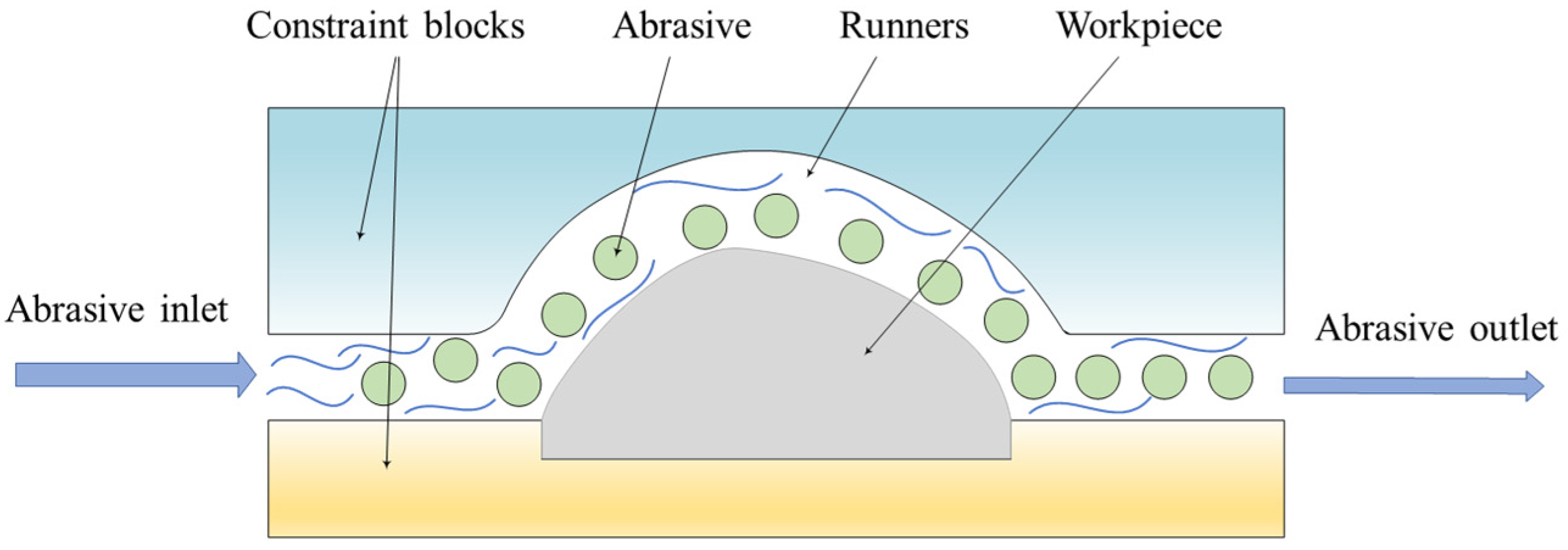
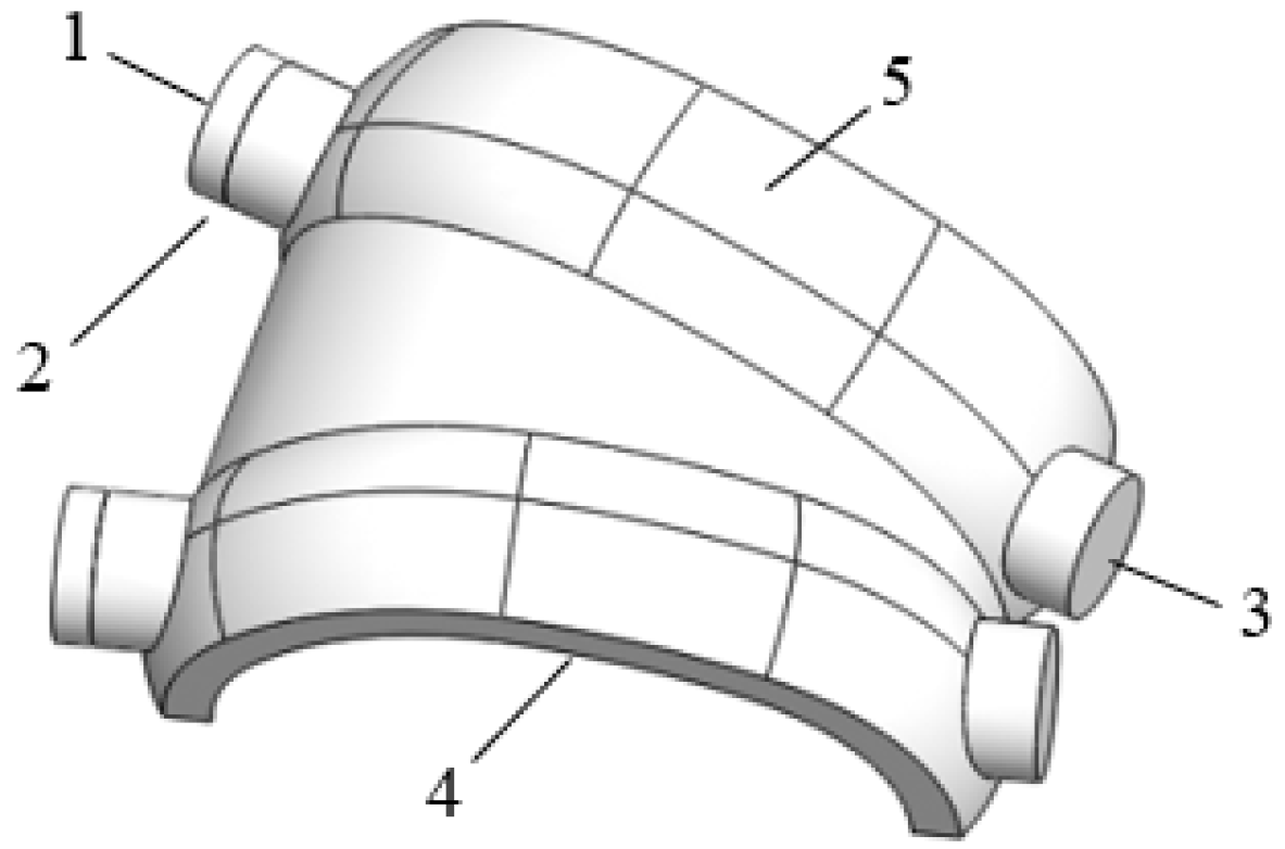
2. Modeling of Knee Joint Surface and Associated Abrasive Flow Machining Channel

Figure 1a shows the scanned structure of a real human knee joint produced with an industrial CT (ZEISS METROTOM 1), where its surface shape is truly disordered and complex; thus, it was difficult for us to conduct the abrasive flow machining of this model. Thus, this kind of scanned model was simplified to the artificial knee joint model in Figure 1b. Surface A and surface B can be represented by six curvature parameters, as shown in Figure 2, and Table 1 shows the values of the curvature parameters of surface A and surface B, respectively. Since surface C is a transition plane, formed with a straight line transitioning along the edges of surface A and surface B, in this study, it mainly focused on the analysis of the abrasive flow machining of the two surfaces A and B.
The abrasive flow machining channel for the artificial knee joint model (see Figure 1b) could be properly designed by configuring a constraining module near the target surface [30]. The abrasive flow machining channel, which can also be called the constrained flow channel, had good contact with the complex surface of the artificial knee joint model, hence, improving the overall machining performance. A schematic representation of the constrained flow channel is shown in Figure 3.

3. Numerical Work

3.1. Model Development

The CFD-based numerical model related to the structure and dimension illustrated in Table 1 and Figure 3 was developed in COMSOL Multiphysics software, as shown in Figure 4, where the abrasive flow entered through inlet one of the constrained flow channel and flowed out through outlet three after passing through the constrained flow channel. At the beginning, it was assumed that the abrasive flow filled the portion between one and two; then, two became the initial boundary interface of the abrasive flow. In addition, four is the upper surface of the artificial knee joint to be machined, and five is the constrained flow channel surface.
The abrasive flow considered in this study was a solid–liquid two-phase flow, where the solid phase used a silicon carbide (SiC) abrasive and the liquid phase used water. In the analysis of the overall characteristics of the abrasive flow field in the constrained flow channel, it was assumed that the diameter of the SiC abrasive was sufficiently small and that the two solid–liquid phases were mixed uniformly. In this case, the two-phase flow could be regarded as a special liquid flow, its density based on the solid-phase quality, and the major simulation parameters are given in Table 2. Further, the standard k-ε turbulence model was selected in COMSOL Multiphysics software to model the abrasive flow, similar to those used in previous studies [1,23,27]. The relative governing equations involved in this software can be found in the user manual, which are common and have been used extensively in similar works [31]. A grid independence test was also carried out before determining the simulation parameters in order to ensure simulation accuracy; all the following works are based on the optimized parameters within the simulation. Figure 5 shows the abrasive flow process with respect to the simulation time, t, from 0 s to 0.1 s, where the value in the colored figure legend represents the proportional volume of abrasive flow in the whole constrained flow channel. The initial speed of the abrasive flow from the left inlet was 5 m/s, which then gradually filled the entire constrained flow channel over time. As can be seen in Figure 5, at t = 0.1 s, the abrasive flow completely filled the entire constrained flow channel, indicating that the abrasive flow fully contacted the target surface to be machined at the time.

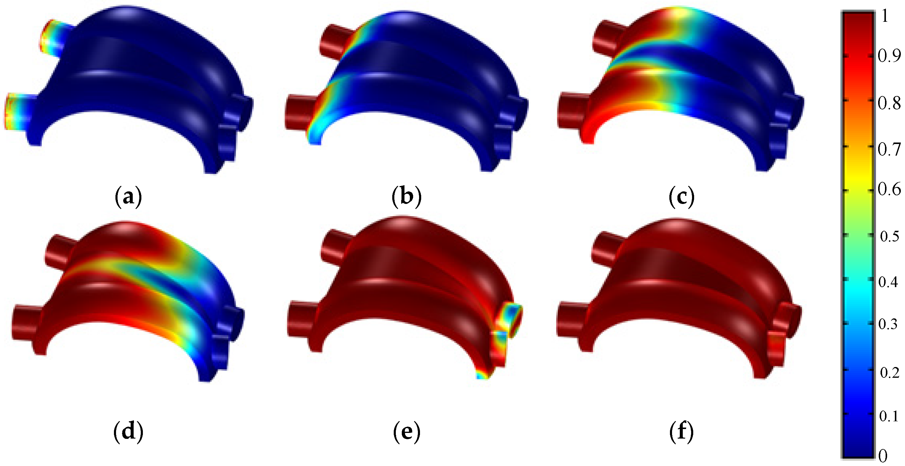
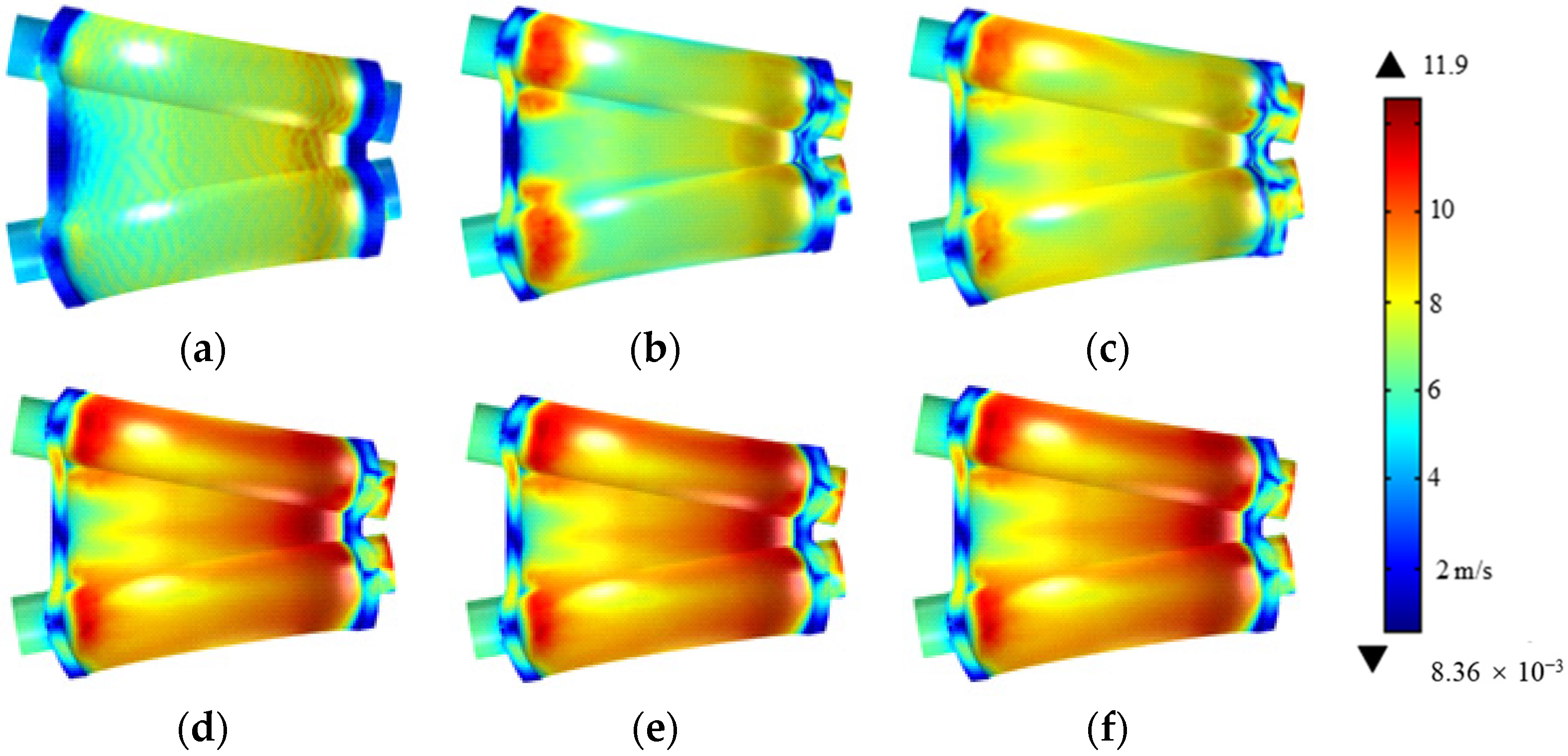
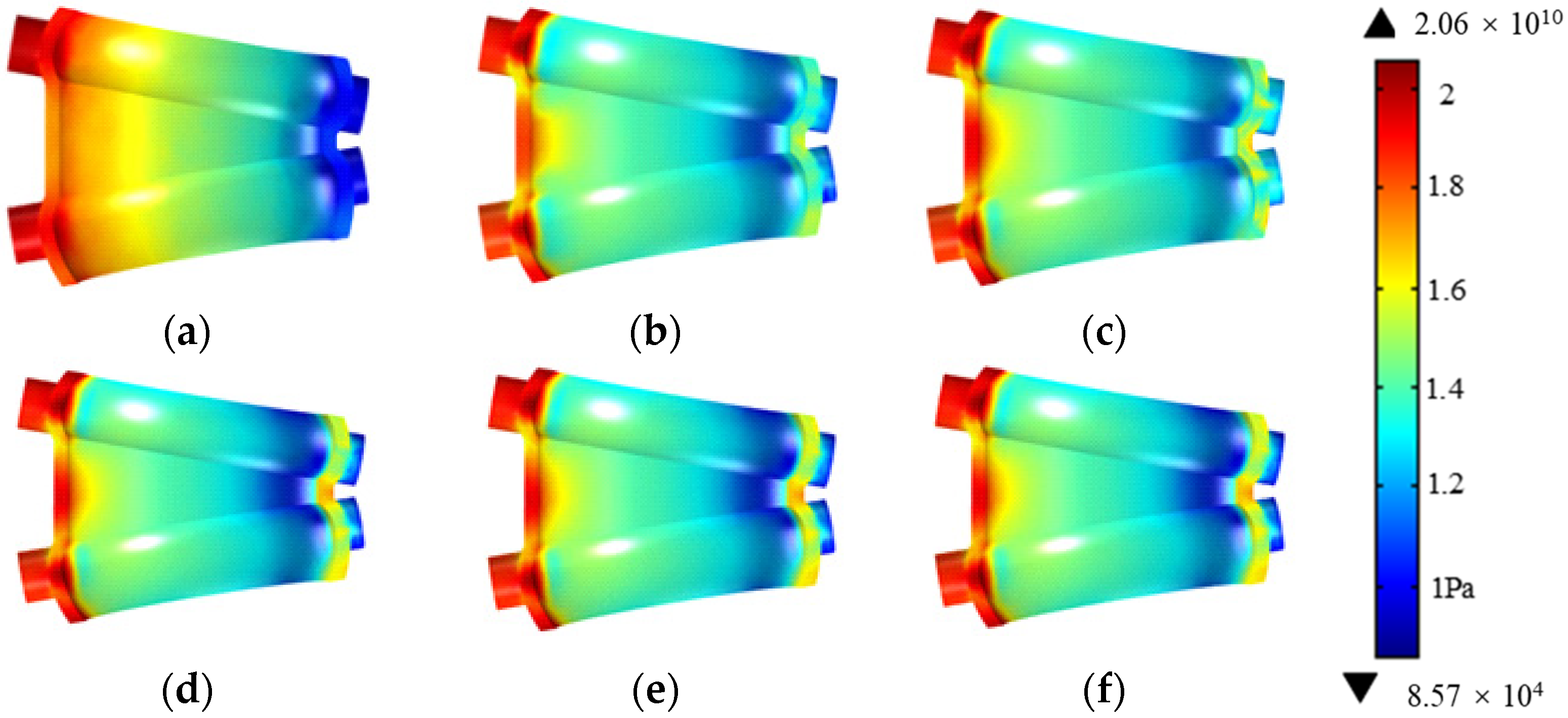
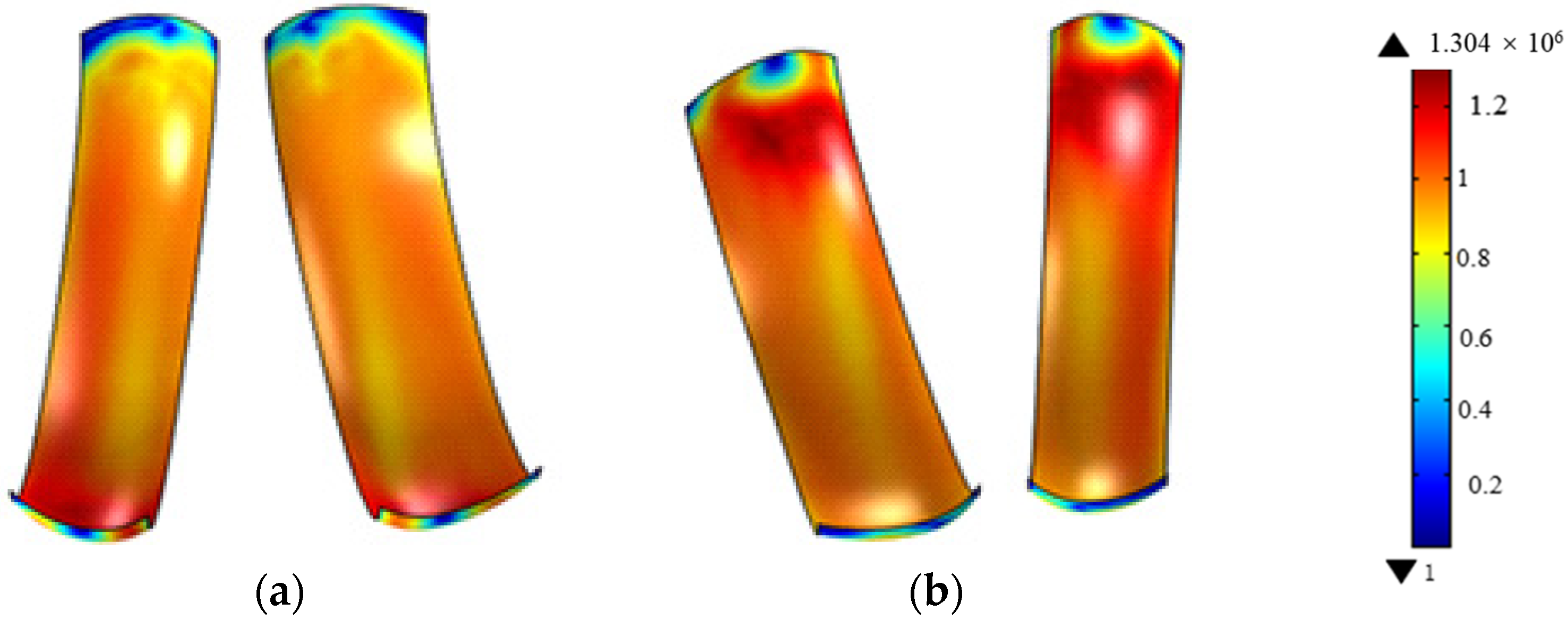
3.2. Numerical Simulation Results and Discussion

Since the characteristics of the abrasive flow on the upper surface of the artificial knee joint had a significant effect on the machining performance, the abrasive flow velocity and pressure in this area were numerically analyzed in this study. Figure 6 shows the distribution of the abrasive flow velocity on the upper surface of the artificial knee joint to be machined. It can be seen from this figure that after the abrasive flow entered the inlet of the channel, the abrasive flow velocity decreased as the cross-sectional area of the channel decreased. During the simulation time considered in this study, the maximum abrasive flow velocity reached approximately 11.9 m/s, and after passing through the constrained flow channel, the velocity decreased until the flow exited through the outlet of the channel. It was also noticed that the distribution of the abrasive flow velocity at the simulation time of 0.025 s was similar to that at the simulation time of 0.05 s, because the abrasive flow almost filled the entire channel at t = 0.025 s, as can be seen in Figure 5e, so it could be deduced that the distribution of the abrasive flow between t = 0.05 s and t = 0.1 s was stable; hence, we could predict that after t = 0.1 s, the distribution of abrasive particle velocity would not change. Therefore, the distribution of the abrasive flow velocity at the simulation time of 0.1 s could be considered as the steady-state during the entire abrasive flow machining process.
Similarly, Figure 7 shows the distribution of the abrasive flow pressure on the upper surface of the artificial knee joint. It can be seen from this figure that the pressure at the inlet of the constrained flow channel was the highest, reaching approximately 2.06 × 10¹⁰ Pa, whereas the pressure at the outlet of the channel was the lowest, which was closer to the range of environmental pressure. It was also interesting to note that, compared with the pressure distribution at t = 0.025 s and the pressure distribution at t = 0.05 s, only the pressure distribution at the outlet of the channel demonstrated a slight difference; meanwhile, compared with the pressure distribution at t = 0.05 s and t = 0.1 s, there was no obvious difference. Thus, similar to the findings in the analysis of the abrasive flow velocity distribution, it could be seen that the pressure distribution between t = 0.05 s and t = 0.1 s did not change, and we predicted that after the simulation time of 0.1 s, the distribution of the abrasive flow pressure would not change either. Therefore, the distribution of the abrasive flow pressure at the simulation time of 0.1 s could be considered the steady-state during the entire abrasive flow machining process.
In addition, the Preston equation states that the material removal rate on the workpiece surface is directly proportional to the cutting speed (V) and loading pressure (P). The material removal mechanism of the abrasive flow machining could be considered to be the microcutting action of abrasive particles on the target surface, where the cutting speed and loading pressure of abrasive particles relative to the target surface actually correspond to the velocity and pressure of the abrasive flow. Therefore, a dimensionless material removal rate model, M = PV/min, was developed to explore the relative machining performance according to the above distribution of abrasive flow velocity and pressure obtained from simulation results. Figure 8 shows the dimensionless material removal rates for the two main machined surfaces, i.e., surface A and surface B in Figure 1b. In order to accurately demonstrate the simulation results, two cases are illustrated in Figure 8, where, in case one, the lower part was set as the inlet and the upper part was set as the outlet, and in case two, the inlet and outlet were set in the opposite positions. It can be seen from Figure 8 that the relative material removal rate near the inlet of the constrained flow channel was relatively large, and the relative material removal rate at the outlet of the constrained flow channel was relatively small. It was also found that in the middle part of the constrained flow channel, the relative material removal rate seemed to be uniform, but in order to realize a good abrasive flow machining performance with a relatively uniform material removal rate across the whole surface, it was recommended that the exchange of the abrasive flow inlet and outlet was necessary.

4. Experimental Work

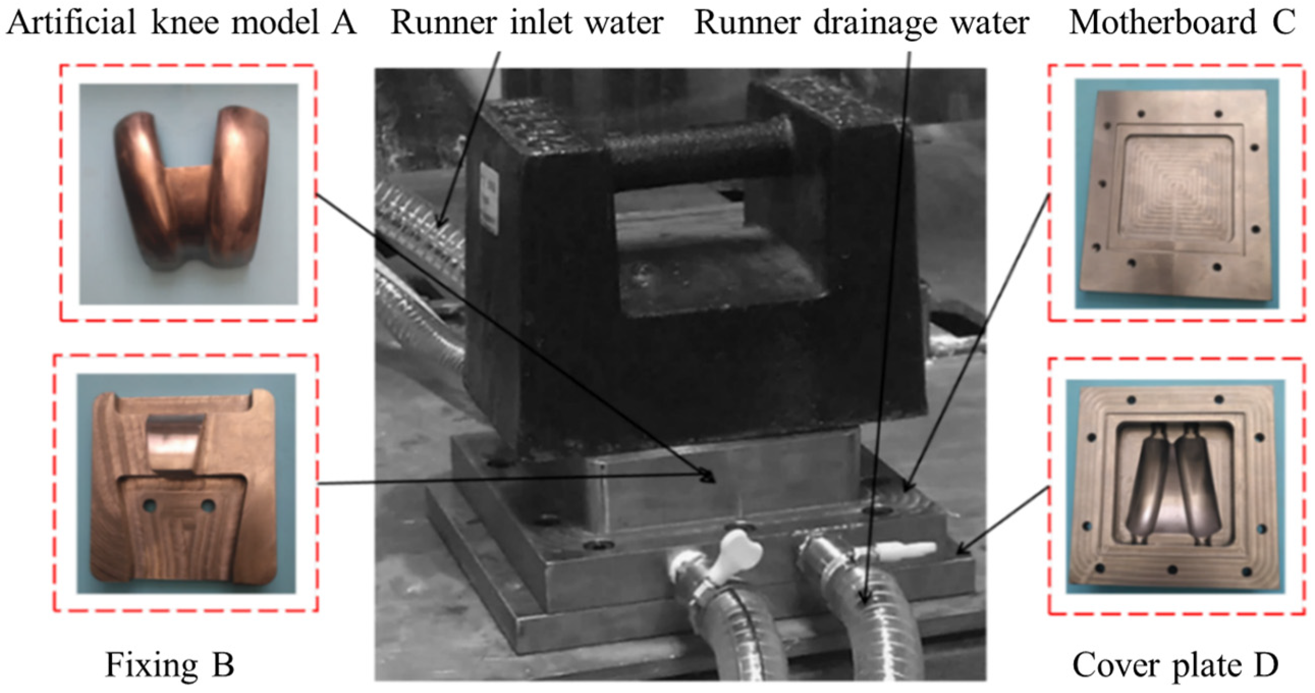
4.1. Experimental Setup

Figure 9 shows the experimental setup, which included the titanium alloy artificial knee joint model A and three restraining parts B, C, and D. The artificial knee joint model A was installed on restraining part B with screws and then both parts were embedded together on base plate C, which was then covered with cover plate D. The small square groove on part C was used for applying the sealant, cooperating with the square protrusion in D to realize the sealing function.
In this experiment, the SiC particles were selected as the abrasive and two different particle sizes of 120 mesh (with an average diameter of 120 μm) and 240 mesh (with an average diameter of 60 μm) were employed for the rough polishing and fine finishing, respectively. The material of the artificial knee joint was composed of a titanium alloy (TC4, Ti-6Al-4V), whose major properties are given in Table 3. The experimental procedure was mainly divided into two abrasive flow machining processes, namely, rough polishing and fine finishing, with the processing parameters given in Table 4. Considering the recommendation of the simulation results, that the exchange of the abrasive flow inlet and outlet was necessary to realize the uniform abrasive flow machining performance, the rough polishing and fine finishing processes were performed at an interval of 1 h with the exchange of the inlet and outlet. During this process, the SiC particles in the abrasive flow were replaced with new ones to guarantee machining quality. Further, three similar titanium alloy artificial knee joint models were used in the experiment, and the average data on surface morphology were taken for a further analysis.

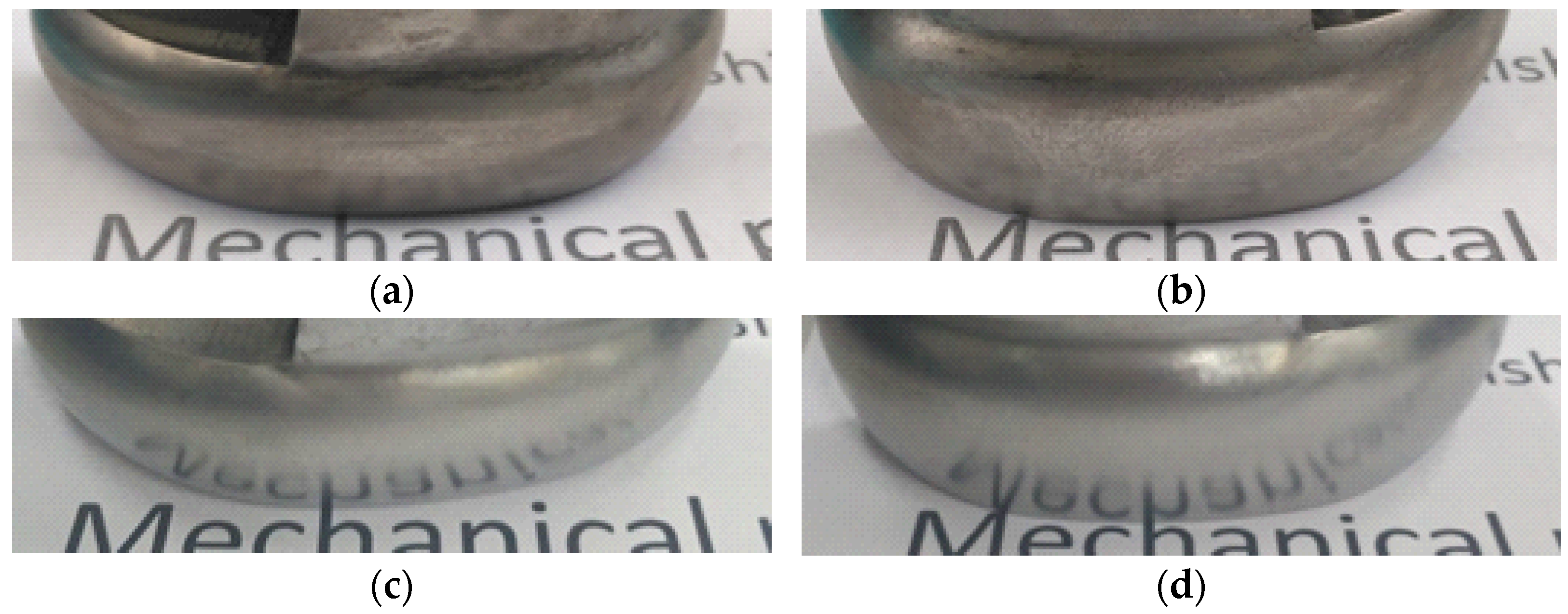
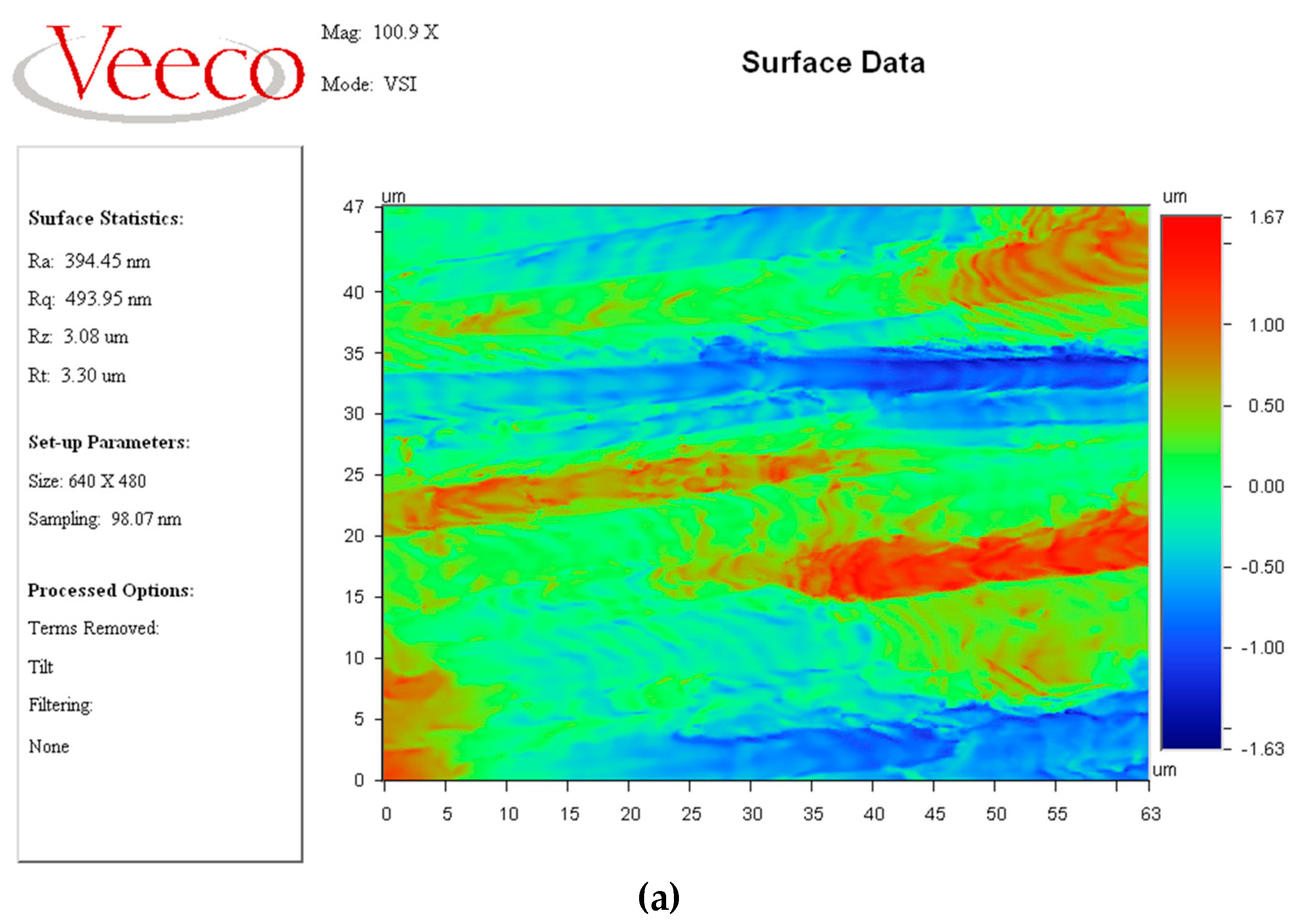
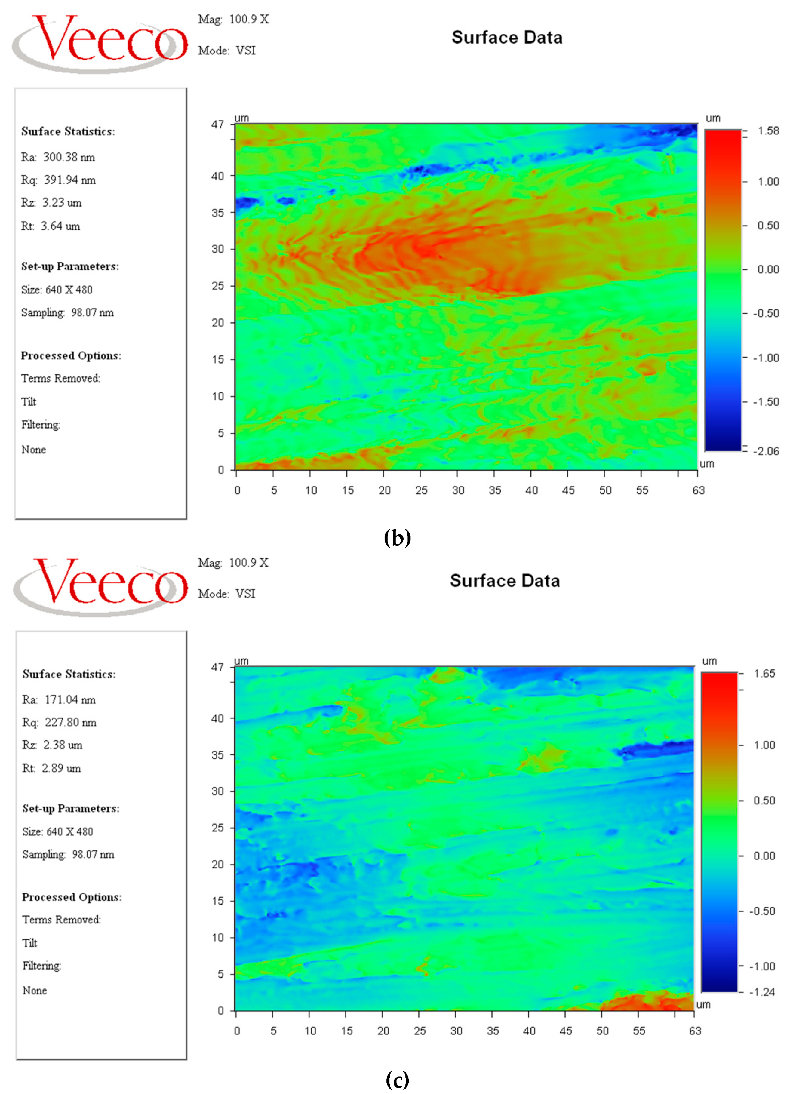
4.2. Results and Discussion

After 16 h of cumulative abrasive flow machining, the experimental observations were qualitatively analyzed, and the results are shown in Figure 10. It can be seen from this figure that the changes in surface quality before and after the machining process were obvious, where surface A and surface B (see Figure 1b) of the titanium alloy artificial knee joint before the machining process essentially could not reflect the word “Mechanical” written on paper, whereas after the abrasive machining process, these two surfaces could reflect each letter more clearly. However, due to the shape of the workpiece, only the lower part of the surface shown in the figure could reflect these letters, and the upper part was blurred because it could not receive the light reflected from the paper. Thus, we demonstrated that abrasive flow machining with a constrained flow channel could significantly improve the surface quality of the titanium alloy artificial knee joint; a further quantitative analysis was conducted as follows in detail.
With the development of the high-tech measuring technique [32], the surface roughness of the workpiece was measured with the assistance of the Veeco NT9800 optical profiler (Veeco Instruments Inc., Plainview, NY, USA). It can be seen from Figure 11 that the original surface roughness of the workpiece was approximately 394 nm, and the surface roughness reduced to approximately 300 nm after 3 h of rough polishing. Finally, after the fine finishing process, the surface roughness was approximately 171 nm. It was also noted that Figure 10a–c clearly show changes in terms of surface roughness during the abrasive flow machining process, in which the surface roughness of the titanium alloy artificial knee joint was continuously reduced, and the surface microstructure gradually changed from being obviously uneven to being relatively flat. This indicated that the abrasive flow machining process significantly improved the surface quality of the artificial knee joint surface.

5. Conclusions

In this paper, a proper constrained flow channel was designed to conduct the abrasive flow machining of s titanium alloy artificial knee joint surface in order to improve the performance and service life of artificial knee joints in the human body. This abrasive flow machining process was first numerically investigated with the assistance of the CFD-based method in COMSOL Multiphysics software, and it was found from the distribution of the abrasive flow velocity that the maximum abrasive flow velocity in the constrained flow channel could reach approximately 11.9 m/s, with even the inlet velocity having the capacity to reach 5 m/s. From the distribution of the dimensionless material removal rate on the target surface, it was also found that the exchange of the abrasive flow inlet and outlet during the machining process could improve the surface finish uniformity. Then, corresponding experiments were conducted to analyze the surface morphology before and after the abrasive flow machining process using the proposed constrained flow channel. It was found from the qualitative study that abrasive flow machining with a constrained flow channel could significantly improve the surface quality of the titanium alloy artificial knee joint by clearly reflecting the word “Mechanical” after the machining process. Further, it was found from the quantitative study that after the fine finishing process, the surface roughness decreased from approximately 394 nm to 171 nm. Therefore, the constrained flow channel proposed in this paper for the abrasive flow machining of a knee joint model is a useful potential method for the fine finishing of titanium alloy artificial joints.

Author Contributions

Conceptualization, R.J. and L.Z.; Data curation, J.C., K.L. and S.L.; Formal analysis, K.L. and S.L.; Funding acquisition, Y.L.; Investigation, R.J.; Project administration, Y.L.; Software, Z.Q.; Supervision, L.Z.; Validation, J.C.; Writing—original draft, Z.Q.; Writing—review and editing, Y.L. All authors have read and agreed to the published version of the manuscript.

Funding

This research was funded by the National Natural Science Foundation of China (U21A20122 and 51575493) and the Zhejiang Provincial Natural Science Foundation of China (LGG19E050025).

Institutional Review Board Statement

Not applicable.

Informed Consent Statement

Not applicable.

Data Availability Statement

The data presented in this study are available on request from the corresponding author. The data are not publicly available due to privacy.

Acknowledgments

The authors would like to thank Zijian Qi for his contribution on the CFD-based simulation and analysis in this study under the cooperation project with Central South University.

Conflicts of Interest

The authors declare that the research was conducted in the absence of any commercial or financial relationships that could be construed as a potential conflict of interest.

References

  1. Zhang, L.; Yuan, Z.M.; Qi, Z.J.; Cai, D.H.; Cheng, Z.C.; Qi, H. CFD-based study of the abrasive flow characteristics within constrained flow passage in polishing of complex titanium alloy surfaces. Powder Technol. 2018, 333, 209–218. [Google Scholar] [CrossRef]
  2. Hu, Y.; Zhou, G.; Yuan, X.; Li, D.; Cao, L.; Zhang, W.; Wu, P. An artificial neural network-based model for roping prediction in aluminum alloy sheet. Acta Mater. 2023, 245, 118605. [Google Scholar] [CrossRef]
  3. Zhang, L.; Zheng, B.J.; Xie, Y.; Ji, R.Q.; Li, Y.B.; Mao, W.B. Control mechanism of particle flow in the weak liquid metal flow field on non-uniform curvature surface based on lippmann model. Front. Mater. 2022, 9, 895263. [Google Scholar] [CrossRef]
  4. Yuan, H.Y.; Yang, W.B.; Zhang, L.; Hong, T. Model development of stress intensity factor on 7057T6 aluminum alloy using extended finite element method. Coatings 2023, 13, 581. [Google Scholar] [CrossRef]
  5. Ji, R.Q.; Zhang, L.Y.; Zhang, L.; Li, Y.B.; Lu, S.S.; Fu, Y.F. Processing method for metallic substrate using the liquid metal lapping-polishing plate. Front. Mater. 2022, 9, 896346. [Google Scholar] [CrossRef]
  6. Li, C.; Piao, Y.C.; Zhang, F.H.; Zhang, Y.; Hu, Y.X.; Wang, Y.F. Understand anisotropy dependence of damage evolution and material removal during nanoscratch of MgF2 single crystals. Int. J. Extrem. Manuf. 2023, 5, 015101. [Google Scholar] [CrossRef]
  7. Li, C.; Piao, Y.; Meng, B.; Hu, Y.; Li, L.; Zhang, F. Phase transition and plastic deformation mechanisms induced by self-rotating grinding of GaN single crystals. Int. J. Mach. Tool. Manu. 2022, 172, 103827. [Google Scholar] [CrossRef]
  8. Qi, H.; Shi, L.; Teng, Q.; Hong, T.; Tangwarodomnukun, V.; Liu, G.; Li, H.N. Subsurface damage evaluation in the single abrasive scratching of BK7 glass by considering coupling effect of strain rate and temperature. Ceram. Int. 2021, 48, 8661–8670. [Google Scholar] [CrossRef]
  9. Xie, X.D.; Zhang, L.; Zhu, L.L.; Li, Y.B.; Hong, T.; Yang, W.B.; Shan, X.H. State of the art and perspectives on surface strengthening process and associated mechanisms by shot peening. Coatings 2023. accepted. [Google Scholar]
  10. Li, C.; Hu, Y.X.; Zhang, F.H.; Geng, Y.Q.; Meng, B.B. Molecular dynamics simulation of laser assisted grinding of GaN crystals. Int. J. Mech. Sci. 2023, 239, 107856. [Google Scholar] [CrossRef]
  11. Qi, H.; Wang, Y.; Qi, Z.; Shi, L.; Fang, Z.; Zhang, L.; Riemer, O.; Karpuschewski, B. A Novel Grain-Based DEM Model for Evaluating Surface Integrity in Scratching of RB-SiC Ceramics. Materials 2022, 15, 8486. [Google Scholar] [CrossRef]
  12. Qi, H.; Xing, W.; Tan, W.; Lin, H.; Guo, H.J.; Chen, M.Z.; Tang, H.P. Effect of the sintering process on mechanical behaviors of Zirconia ceramics by NanoParticle Jetting. Ceram. Int. 2023. submitted. [Google Scholar]
  13. Qi, H.; Fan, J.M.; Wang, J.; Li, H.Z. On the erosion process on quartz crystals by the impact of multiple high-velocity micro-particles. Tribol. Int. 2016, 95, 462–474. [Google Scholar] [CrossRef]
  14. Wang, Y.Y.; Wang, Z.; Ni, P.C.; Wang, D.J.; Guo, S.H.; Chen, Z.Z. Experimental and numerical study on regulation of cutting temperature during the circular sawing of 45 steel. Coatings 2023. accepted. [Google Scholar]
  15. Ji, P.J.; Zhang, J.J.; Xie, X.D.; Ying, R.M.; Zhang, L. Review on wear characteristics of artificial hip joint and associated physical training. Front. Mater. 2023. accepted. [Google Scholar]
  16. Xie, Y.; Gui, F.X.; Wang, W.J.; Chien, C.F. A two-stage multi-population genetic algorithm with heuristics for workflow scheduling in heterogeneous distributed computing environments. IEEE Trans. Cloud Comp. 2022, in press. [Google Scholar] [CrossRef]
  17. Li, L.; Qi, H.; Yin, Z.; Li, D.; Zhu, Z.; Tangwarodomnukun, V.; Tan, D. Investigation on the multiphase sink vortex Ekman pumping effects by CFD-DEM coupling method. Powder Technol. 2020, 360, 462–480. [Google Scholar] [CrossRef]
  18. Qian, H.N.; Chen, M.K.; Qi, Z.J.; Teng, Q.; Qi, H.; Zhang, L.; Shan, X.H. Review on research and development of abrasive scratching of hard brittle materials and its underlying mechanisms. Crystals 2023, 13, 428. [Google Scholar] [CrossRef]
  19. Davies, P.J.; Fletcher, A.J. The assessment of the rheological characteristics of various polyborosiloxane grit mixtures as utilized in the abrasive flow machining process. Proc. Inst. Mech. Eng. Part C J. Mech. Eng. Sci. 1995, 209, 409–418. [Google Scholar] [CrossRef]
  20. Xu, L.; Chen, H.Y.; Lyu, B.H.; Hang, W.; Yuan, J.L. Study on rheological properties and polishing performance of viscoelastic material for dilatancy pad. Precis. Eng. 2022, 77, 328–339. [Google Scholar] [CrossRef]
  21. Williams, R.E.; Rajurkar, K.P. Metal removal and surface finish characteristics in abrasive flow machining. Mater. Sci. 1989, 38, 93–106. [Google Scholar]
  22. Qi, H.; Cheng, Z.C.; Cai, D.H.; Yin, L.Z.; Wang, Z.W.; Wen, D.H. Experimental study on the improvement of surface integrity of tungsten steel using acoustic levitation polishing. J. Mater. Process. Technol. 2018, 259, 361–367. [Google Scholar] [CrossRef]
  23. Qi, H.; Xie, Z.; Hong, T.; Wang, Y.Y.; Kong, F.Z.; Wen, D.H. CFD modelling of a novel hydrodynamic suspension polishing process for ultra-smooth surface with low residual stress. Powder Technol. 2017, 317, 320–328. [Google Scholar] [CrossRef]
  24. Uhlmann, E.; Schmiedel, C.; Wendler, J. CFD simulation of the abrasive flow machining process. Procedia CIRP 2015, 31, 209–214. [Google Scholar] [CrossRef]
  25. Fu, Y.Z.; Wang, X.P.; Gao, H.; Wei, H.B.; Li, S.C. Blade surface uniformity of blisk finished by abrasive flow machining. Int. J. Adv. Manuf. Technol. 2016, 84, 1725–1735. [Google Scholar] [CrossRef]
  26. Zhang, L.; Ji, R.Q.; Fu, Y.F.; Qi, H.; Kong, F.Z.; Li, H.N.; Tangwarodomnukun, V. Investigation on particle motions and resultant impact erosion on quartz crystals by the micro-particle laden waterjet and airjet. Powder Technol. 2020, 360, 452–461. [Google Scholar] [CrossRef]
  27. Qi, H.; Qin, S.K.; Cheng, Z.C.; Teng, Q.; Hong, T.; Xie, Y. Towards understanding performance enhancing mechanism of micro-holes on K9 glasses using ultrasonic vibration-assisted abrasive slurry jet. J. Manuf. Process. 2021, 64, 585–593. [Google Scholar] [CrossRef]
  28. Peng, W.S.; Ma, L.; Wang, P.; Cao, X.W.; Xu, K.; Miao, Y.C. Experimental and CFD investigation of flow behavior and sand erosion pattern in a horizontal pipe bend under annular flow. Particuology 2023, 75, 11–25. [Google Scholar] [CrossRef]
  29. Kumar, M.; Kumar, V.; Kumar, A.; Yadav, H.N.S.; Das, M. CFD analysis of MR fluid applied for finishing of gear in MRAFF process. Mater. Today Proc. 2021, 45, 4677–4683. [Google Scholar] [CrossRef]
  30. Ji, S.; Tang, B.; Tan, D.; Gong, B.; Yuan, Q.; Pan, Y. Structured surface softness abrasive flow precision finish machining and its abrasive flow dynamic numerical analysis. Chin. J. Mech. Eng. 2010, 46, 178–184. [Google Scholar] [CrossRef]
  31. Luo, B.; Yan, Q.S.; Chai, J.F.; Song, W.Q.; Pan, J.S. An ultra-smooth planarization method for controlling fluid behavior in cluster magnetorheological finishing based on computational fluid dynamics. Precis. Eng. 2022, 74, 358–368. [Google Scholar] [CrossRef]
  32. Wu, B.; Li, D.R.; Zhou, Y.; Zhu, D.; Zhao, Y.P.; Qiao, Z.K.; Chen, B.; Wang, X.L.; Lin, Q. Construction of a calibration field of absolute gravity in a cave using the Cold Atom Gravimeter. Sensors 2023. submitted. [Google Scholar]
Figure 1. Knee joint model: (a) scanned knee joint model; (b) artificial knee joint model.
Crystals 13 00430 g001
Figure 2. Schematic representation of curvature parameters in surface A and surface B.
Crystals 13 00430 g002
Figure 3. Schematic representation of constrained flow channel.
Crystals 13 00430 g003
Figure 4. Model and boundary conditions: 1—runner inlet; 2—initial interface; 3—runner outlet; 4—upper surface of artificial knee joint; 5—constrained flow channel surface.
Crystals 13 00430 g004
Figure 5. Abrasive flow process with respect to simulation time: (a) t = 0 s; (b) t = 0.005 s; (c) t = 0.01 s; (d) t = 0.015 s; (e) t = 0.025 s; (f) t = 0.1 s.
Crystals 13 00430 g005
Figure 6. Distribution of abrasive flow velocity across upper surface of artificial knee joint: (a) t = 0 s; (b) t = 0.005 s; (c) t = 0.01 s; (d) t = 0.025 s; (e) t = 0.05 s; (f) t = 0.1 s.
Crystals 13 00430 g006
Figure 7. Distribution of abrasive flow pressure on upper surface of artificial knee joint: (a) t = 0 s; (b) t = 0.005 s; (c) t = 0.01 s; (d) t = 0.025 s; (e) t = 0.05 s; (f) t = 0.1 s.
Crystals 13 00430 g007
Figure 8. Dimensionless material removal rate: (a) case 1: lower inlet and upper outlet; (b) case 2: upper inlet and lower outlet.
Crystals 13 00430 g008
Figure 9. Experimental setup.
Crystals 13 00430 g009
Figure 10. Comparison of surface quality before and after abrasive flow machining process: (a) original surface A; (b) original surface B; (c) surface A after machining process; (d) surface B after machining process.
Crystals 13 00430 g010
Figure 11. Comparison of surface roughness: (a) original surface of workpiece; (b) after 3 h rough polishing; (c) after fine finishing.
Crystals 13 00430 g011aCrystals 13 00430 g011b
Table 1. Values of curvature parameters in surface A and surface B.
Curvature ParametersSurface A (mm)Surface B (mm)
R13030
R24545
R3100100
R44040
R522.515
R622.540
Table 2. Simulation parameters.
ParametersValuesUnit
Temperature22°C
Environmental pressure1.01325 × 105Pa
Inlet speed5m/s
Abrasive flow density1.333 × 103kg/m3
Abrasive flow viscosity1.011 × 10−3Pa·s
Table 3. Major material properties of TC4.
Density, g/cm3Young’s Modulus, GPaPoisson’s RatioYield Stress, MPa
4.431040.31880
Table 4. Experimental processing parameters.
Processing ParametersValues
Temperature22 °C
AbrasiveSiC
FluidWater
Abrasive particle concentration10%
Abrasive particle inlet velocity5 m/s
Average diameter of SiC for rough polishing120 μm
Rough polishing time10 h
Average diameter of SiC for fine finishing60 μm
Fine finishing time8 h
Disclaimer/Publisher’s Note: The statements, opinions and data contained in all publications are solely those of the individual author(s) and contributor(s) and not of MDPI and/or the editor(s). MDPI and/or the editor(s) disclaim responsibility for any injury to people or property resulting from any ideas, methods, instructions or products referred to in the content.

