Article

On the Hot Deformation of a Fe-Al-Ta Iron Aluminide Prepared via Laser Powder Bed Fusion

1
Physical Metallurgy and Materials Technology, Brandenburg University of Technology Cottbus-Senftenberg, 03044 Cottbus, Germany
2
Hybrid Manufacturing, Brandenburg University of Technology Cottbus-Senftenberg, 03044 Cottbus, Germany
3
Helmholtz-Zentrum Berlin für Materialien und Energie GmbH, Hahn-Meitner-Platz 1, 14109 Berlin, Germany
*
Author to whom correspondence should be addressed.
Crystals 2023, 13(4), 627; https://doi.org/10.3390/cryst13040627
Submission received: 24 February 2023 / Revised: 13 March 2023 / Accepted: 22 March 2023 / Published: 5 April 2023
(This article belongs to the Special Issue Hot Deformation Characteristics of Metallic Materials)

Abstract

:
In the present work, a combined process of laser powder bed fusion (LPBF) and hot working in terms of microstructure refinement was investigated for Fe-25Al-1.5Ta alloy samples. Uniaxial compression tests were carried out parallel and perpendicular to the building direction (BD) at 1000 °C, where BCC A2-phase was stable, at a strain rate of 0.0013 s−1. The true stress–true strain curves indicated a broad flow stress peak followed by a slight decrease, which is typical for dynamic recrystallization (DRX) of conventional BCC metals such as ferritic iron. A negligible dependence in the flow stress behavior on the compression direction was observed. DRX initiated at a stress of 18.7 MPa for the sample compressed parallel to the BD, corresponding to a true strain of 0.011, and at 18.1 MPa for the samples compressed normal to the BD, which corresponded to a true strain of 0.010. The microstructural investigations by electron backscatter diffraction (EBSD) showed that the relatively coarse and elongated grains of the as-LPBF builds were significantly refined after hot working. The microstructure of the compressed samples mainly consisted deformed grains. These were fragmented by sub-grains bounded by low-angle boundaries independent of the compression axis, indicating the occurrence of dynamic recovery (DRV) during hot working. In addition, a few equiaxed, small grains were observed in the pre-existing grain boundaries, which formed due to DRX. Most pores in the as-LPBF builds were closed after hot compression, particularly in the central region of the deformed specimens where the compressive stress state is dominant. In summary, hot compression reveals a practical thermomechanical post-processing treatment for Fe-Al-Ta iron aluminides built by LPBF. The hot working refines the epitaxially elongated microstructure of the as-LPBF builds by DRV/DRX and reduces the porosity.

1. Introduction

Due to a combination of desirable properties, including low density, high specific yield strength, low material cost, and excellent oxidation, as well as corrosion resistance, iron aluminides have qualified to replace heat-resistant steels or, in some cases, even superalloys in high-temperature applications of up to 800 °C [1,2,3]. Iron aluminides with a strengthening Laves phase revealed several advantages over their binary counterparts, such as superior creep resistance up to intermediate temperatures [4,5,6,7]. Likewise, films of Laves phase prevented hydrogen uptake along grain boundaries and thus inhibited embrittlement by the ambient medium [3]. In addition, Laves phase precipitation at grain boundaries impeded coarsening/abnormal grain growth at high temperatures during thermomechanical treatments or service [8].
Tantalum (Ta) is an effective alloying element for strengthening Fe–Al alloys, forming the hard and brittle ternary Laves phase (Fe, Al)2Ta with a hexagonal C14 crystal structure. In particular, the Fe-25Al-2Ta (all compositions are given in atomic percent throughout the text unless otherwise stated) alloy outperforms the martensitic-ferritic steel P92 (X10CrWMoVNb9-2) at 650 °C in terms of creep strength [6]. Likewise, the Fe-25Al-1.5Ta alloys produced by casting and spark plasma sintering demonstrated a high degree of hot deformability over a wide temperature and strain rate range [9,10,11].
Although the Laves phase can be used to strengthen Fe–Al alloys, its non-controllable distribution, specifically during solidification from the melt, and the strong coarsening tendency of the precipitates at elevated temperatures, have prevented any significant alloy developments [12]. In this context, state-of-the-art metal additive manufacturing (AM) can produce these aluminides with uniformly dispersed fine Laves phase particles without coarsening, owing to its short solidification time and high cooling rates [13].
In an earlier study of the authors [13], crack-free and dense Fe-25Al-1.5Ta samples were produced via laser powder bed fusion (LPBF). The builds were characterized by relatively coarse and columnar grains growing epitaxially out of the substrate, were several millimeters wide, and extended over several layers along the building direction. The grains also exhibited a relatively strong microtexture close to <0 0 1> with respect to the building direction. Therefore, a suitable post-processing treatment is required to reduce the defects and refine the microstructure of the Fe-Al-Ta builds.
The additively manufactured parts are often subject to post-processing treatments, such as hot isostatic pressing (HIP) and heat treatment, to close the residual porosity and adjust the desired microstructure to improve their mechanical performance. However, the HIP process is time-consuming, leading to grain and precipitate coarsening [14]. Thus, the fine microstructure created by AM cannot be directly inherited into the final component. As an alternative method, hot deformation was qualified as a promising post-processing treatment for additively manufactured parts to reduce the solidification and processing defects, refine the microstructure through dynamic recrystallization, and, thus, improve the mechanical properties of AM parts [15,16,17,18,19]. For example, Sizova et al. [16] proposed that the hot working of titanium aluminide preforms made with LPBF is an alternative to HIP for series production. Hot working transformed and refined the microstructure, while during HIP, the coarsening of the microstructure was observed. Hybrid AM and hot working allow the advantage of AM and traditional forming methods to be utilized. For example, AM can be used to prepare preforms which are then forged into the final product [20,21,22,23]. This combination shortens the conventional multi-step forging processes, saves costs for dies, and at the same time, improves the mechanical properties of the AM material. Most reports on the hot deformation of AM alloys focus mainly on titanium alloys, especially Ti-6Al-4V [17,24,25,26], superalloys [27,28,29,30], steels [31,32], and Al alloys [33,34]. Although the beneficial effects of hot working on the microstructure and properties of those alloys have been confirmed, the scientific literature knowledge on the hot deformation behavior of AM preforms made of other less-commonly used alloys is still insufficient. In particular, knowledge of the workability of additively manufactured iron aluminide alloys is limited [35]. Nevertheless, it is crucial to use advanced iron aluminides for critical components [36,37].
The present study focuses on the process combination of LPBF and hot compression in terms of the microstructure refinement for the Fe-25Al-1.5Ta alloy. Uniaxial hot-compression tests were carried out at 1000 °C with a strain rate of 0.0013 s−1, parallel and perpendicular to the building direction. The obtained stress–strain behavior is analyzed depending on the loading direction, and underlying flow-softening mechanisms are elucidated by electron microscopy.

2. Materials and Methods

2.1. Starting Material

Gas-atomized Fe-25Al-1.5Ta alloy powder batch with a fraction size of +10/−45 µm and an average particle size of d50 = 22.6 μm was used for LPBF. More details on the initial powder characterization are given in [13].
A 400 W AconityMIDI (Herzogenrath, Germany) laser source was used to fabricate LPBF builds under argon atmosphere. The laser power, the scanning speed, the layer thickness, and the hatching distance were 250 W, 1000 mm/s, 50 μm, and 90 μm, respectively. Parallel stripes with a width of 5 mm were built using a 67° rotation scanning strategy on a stainless steel build plate preheated to 800 °C.

2.2. Compression Tests

Cylindrical specimens for the hot-compression tests with a diameter of 5 mm and a height of 8 mm were cut from the LPBF builds using an electric discharge wire-cutting machine. Lab-scale uniaxial isothermal compression tests were conducted on a DIL805A/D/T deformation dilatometer under the Ar atmosphere. The specimens were heated to the deformation temperature (1000 °C) with an induction heating system at a heating rate of 10 K/s and kept isothermal for 3 min before compression to homogenize the temperature within the specimens. The specimens were compressed at 1000 °C with a strain rate of 0.0013 s−1 up to a true strain of 0.8 parallel and perpendicular to the building direction. The deformation condition of 1000 °C/0.0013 s−1 was chosen because the studied alloy in the as-cast state revealed a high degree of deformability within the processing window of 1000–1100 °C/0.0013–0.01 s−1 [10]. Based on Thermo-Calc computations, we suppose that the alloy locates in (bcc/A2 + C14)-phase field during deformation at 1000 °C [9]. After deformation, the deformed specimens were cooled immediately to preserve the high-temperature microstructures.

2.3. Microstructure Characterization

Microstructure investigations were carried out on sections parallel to the compression axis (CA). The cut surfaces were mechanically polished and vibration polished to obtain mirror-smooth surfaces. All observations were carried out in the center of the deformed specimens. A scanning electron microscope (SEM) TESCAN MIRA II (Brno, Czech Republic) equipped with energy-dispersive X-ray spectroscopy (EDX—Oxford Instruments Aztec system, Abingdon, UK) and high-resolution electron backscatter diffraction (EBSD—Oxford Instruments Aztec System, UK) detectors were used for characterization.
The low- and high-angle grain boundaries (LAGBs/HAGBs) were identified with misorientations of 2–15° and more than 15°, respectively. The individual grains were outlined with a threshold angle of 10°. EBSD orientation imaging microscopy (OIM) maps were employed to visualize the substructures within grains. In the current study, grain reference orientation deviation (GROD)-axis maps were applied to visualize local intercrystalline distortions within the grains. The GROD-axis map displayed the orientation heterogeneities that evolved in the samples [38]. For each pixel within the grain, the misorientation of the point relative to a reference orientation for the grain to which the pixel belonged was calculated and displayed as a color according to the IPF color key.
The phase identification was carried out by a Bruker D8 ADVANCE X-ray diffractometer (Bruker, Billerica, MA, USA) using Cu-Kα1 radiation.

3. Results

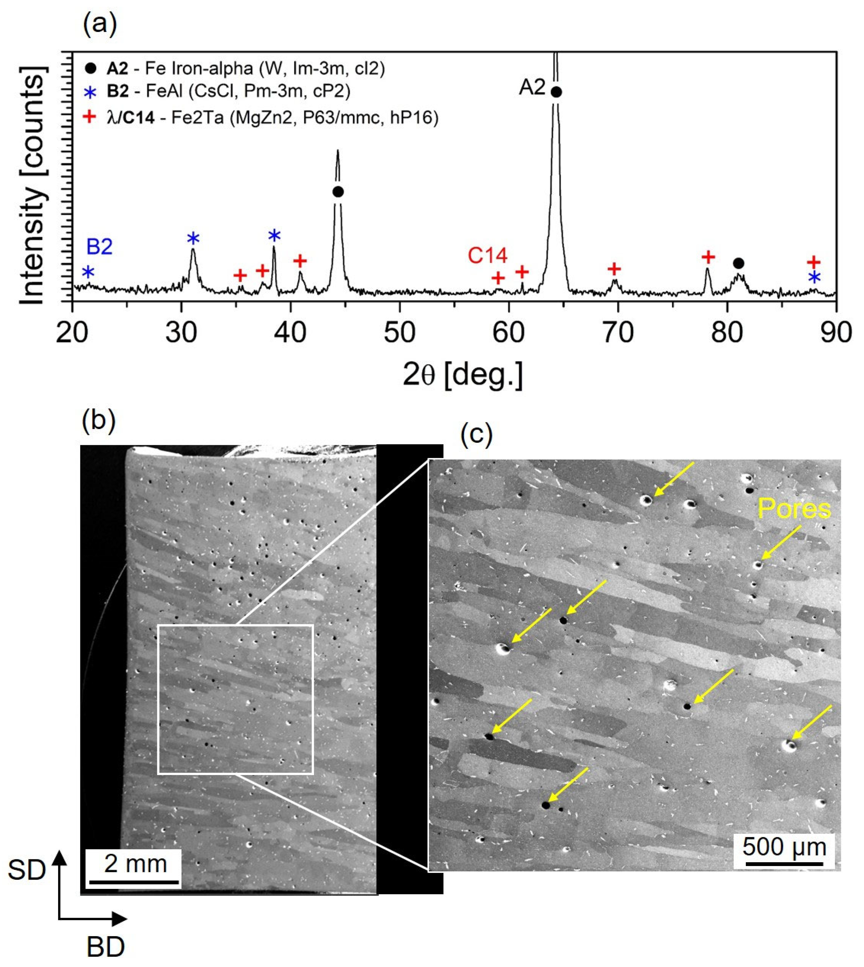
3.1. Microstructure Characterization of the LPBF Builds

Figure 1a exhibits the X-ray diffractogram of the LPBF-produced Fe3Al-1.5Ta sample. The XRD pattern displays characteristic superstructure peaks of (100) and (101) B2-type ordered structure and primary reflections of the disordered A2 α-(Fe, Al) phase. The characteristic (111)D03 and (311)D03 reflections from the D03-type ordered structures are not present. Besides the matrix reflections, peaks of the C14 (Fe, Al)2Ta Laves phase are also observed.
Figure 1b presents typical BSE-SEM micrographs of LPBF-manufactured cylindrical specimens for compression tests. The microstructure consists primarily of columnar grains elongated along the BD. A few pores are also visible, as marked by arrows in the high-resolution image in Figure 1c. A comparable grain morphology was reported for Fe3Al parts fabricated by AM [39]. The high magnification image in Figure 1c shows that the Fe-Al matrix grains are decorated with a white contrast phase. According to previous studies [9,40] and the XRD results from Figure 1a, this phase corresponds to the C14 Laves phase (Fe, Al)2Ta with hexagonal crystal symmetry. The low solubility of Ta in the binary Fe-Al phases leads to the precipitation of the ternary Laves phase when small amounts of Ta are added to Fe(Al) solid solution phases [41]. The C14 precipitate particles are relatively homogeneously distributed throughout the microstructure, both at the Fe-Al grain boundaries (GBs) and within the grains.

3.2. Flow Stress Behavior and Work Hardening Behavior

Figure 2a shows the true stress–true strain curve of the LPBF-fabricated Fe-25Al-1.5Ta samples hot compressed at 1000 °C with a strain rate of 0.0013 s−1 up to a true strain of 0.8. No significant differences in flow behavior and magnitude of flow stress are observed between the specimens compressed parallel or perpendicular to the BD. The sample loaded perpendicular to the BD exhibits slightly lower flow stress, suggesting that less force is required for deformation than for the sample loaded parallel to the BD. The stress–strain curves show a broad flow stress peak followed by a slight decrease. This shape is typical for the occurrence of dynamic recrystallization (DRX) in conventional BCC metals such as ferritic iron [42]. The rise in flow stress after a steady state is due to the dominance of friction and bulging of the specimens.
DRX starts at a critical strain during hot deformation, which can be determined from the flow curves. The critical stress for the initiation of DRX can be identified from the inflection point on the strain hardening rate (θ  =  /) versus the flow stress (σ) curve. This kind of curve can be described by a third-order polynomial equation that fits the experimental θ − dσ data from zero to the peak stress as follows [43]:
θ = A σ 3 + B σ 2 + C σ + D
where: θ  =  / and A, B, C, and D are constants for a given set of deformation conditions. Differentiation of this equation with respect to σ results in:
d θ d σ = 3 A σ 2 + 2 B σ + C
The minimum point of this second-order equation corresponds to the critical stress:
d 2 θ d σ 2 = 0   6 A σ c + 2 B = 0     σ c = B 3 A
Figure 2b shows the work hardening rate (θ) as a function of flow stress (σ) for the LPBF-manufactured Fe-25Al-1.5Ta alloys compressed parallel and perpendicular to the BD. At the early stage of imposed deformation, dislocations accumulate, and their density increases; therefore, the work hardening increases rapidly to a peak value. DRX will initiate when the strain (density of dislocations) reaches a certain level, namely critical strain εc, and the corresponding stress is the critical stress σc. The occurrence of DRX continuously reduces the work hardening rate up to the peak stress where the work hardening reaches zero. At higher strains, flow softening is dominant until a dynamic equilibrium between hardening and softening mechanisms is reached. The critical stress and strain values for the onset of DRX in the deformed samples and their correlation with the peak values are listed in Table 1 with respect to the compression direction. The DRX initiates at a stress of 18.7 MPa for the sample compressed parallel to the BD, corresponding to a true strain of 0.011, and at a stress of 18.1 MPa for the samples compressed normal to the BD, which corresponds to a true strain of 0.010. Therefore, it can be concluded that DRX initiates at comparable stress and strain values in the samples compressed parallel or perpendicular to the BD.

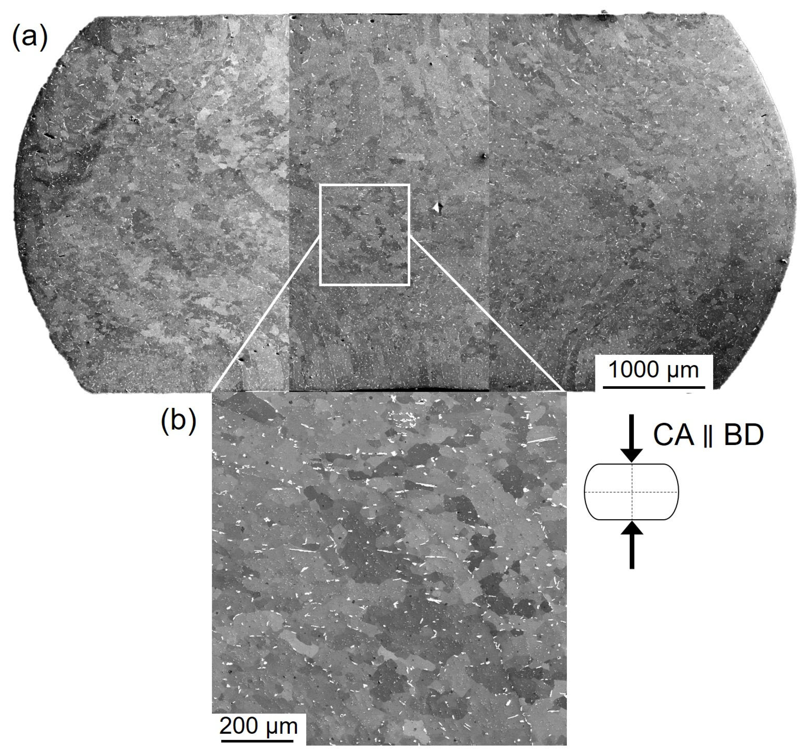
3.3. Characterization of Deformed Specimens

Figure 3a presents typical BSE-SEM micrographs of the LPBF-manufactured samples deformed at 1000 °C/0.0013 s−1 up to a true strain of 0.8, where the compression axis (CA) was parallel to the BD. The material is subjected to a slight deformation in the areas close to the forging dies (known as the dead metal zone). In contrast, deformation is localized mainly in the central region of the specimens, characterized by heavily deformed grains as shown in a high-resolution image in Figure 3b. No cracks were observed in the deformed specimens, while a few pores are still visible after deformation, mainly near to the low-deformation and bulged zones. The central region of the deformed specimens, where the material is subject to high deformation under compressive stress, is almost free of pores.
Figure 3b exhibits that the elongated columnar grains of the LPBF-fabricated builds (see Figure 1b) have refined into relatively equiaxed smaller sub-grains bounded by LAGBs. The EBSD studies are performed on specimens deformed parallel and perpendicular to the BD to elucidate the underlying softening mechanism(s). Figure 4a,b represent the image quality (IQ) maps superimposed with grain boundary misorientation maps for the LPBF-fabricated Fe-25Al-1.5Ta specimens hot compressed up to a true strain of 0.8 at 1000 °C/0.0013 s−1, where CA is either parallel (a) or perpendicular (b) to the BD. The low- and high-angle grain boundaries (LAGBs and HAGBs) are identified with misorientations of 2–15° and more than 15° and are outlined in blue and black lines, respectively. Hot deformation substructures in terms of LAGBs are observed in both specimens. In the present study, grain reference orientation deviation (GROD)-axis maps are applied to visualize substructures within the grains. For the GROD axis map, the misorientation axis for each pixel within a grain with respect to the average orientation of the grain is calculated and displayed as a color according to the IPF color key. Figure 4c,d exhibit GROD-axis maps for deformed specimens, where CA is either parallel (c) or perpendicular (d) to the BD. The microstructure of both specimens has been refined into substructures with different orientations during deformation.
In addition to the sub-grains, some small equiaxed grains are visible on the original GBs of both deformed specimens (yellow arrows point out a few examples).

4. Discussion

Dynamic softening (restoration) processes occur during deformation at high temperatures, which can significantly affect the microstructure and mechanical properties of the finished components [44]. The present study reveals that post-AM hot working alters the microstructure of the Fe-25Al-1.5Ta alloy samples fabricated by LPBF. The initial microstructure of the LPBF builds primarily consists columnar grains epitaxially elongated along the building direction, including some pores (see Figure 1). Hot compression up to a true strain of 0.8 at 1000 °C/0.0013 s−1 leads to grain refinement and porosity closure in the deformed specimens, as shown in Figure 3. No cracks are observed in the deformed specimens, while a few pores are still visible after deformation mainly next to the low-deformation and bulged zones. The central region of the deformed specimens, where the material is strongly deformed under the dominant compressive stress, is almost free of porosity. This indicates the advantages of hot working as a post-processing tool to reduce defects and refine the microstructure of AM samples.
The true stress–strain curve of the LPBF-built samples subjected to hot compression at 1000 °C/0.0013 s−1 exhibits a broad flow stress peak followed by a slight decrease after the stress peak (see Figure 2). This shape is not similar to the typical DRX type in FCC metals and alloys, where the flow curve shows evident peak stress followed by significant flow softening (and sometimes stress oscillations). The present stress–strain curves are typical of DRX in conventional BCC metals, such as ferritic iron [42], where no significant stress drop in stress–strain curves is observed despite the occurrence of DRX.
The EBSD analysis in Figure 4 shows that the majority of deformed grains were fragmented into a substructure network, and most of these sub-boundaries have already transformed into low-angle and slightly further into high-angle grain boundaries by absorbing gliding dislocations during hot deformation. This indicates the occurrence of DRV and maybe continuous DRX during hot deformation. It is reported that BCC Fe3Al-based alloys exhibit a strong tendency for DRV. The primary softening mechanisms often reported for these alloys during hot deformation within the A2-phase field include DRV (substructure formation), continuous DRX, and superplasticity [45,46,47], depending on the imposed deformation conditions. In an earlier study of the authors, strong DRV followed by recrystallization (i.e., continuous DRX) at 900 °C/1 s−1 and fine-grain superplasticity (average grain size of ≈ 7 μm) at 1100 °C/10−3 s−1 were observed in an Fe-25Al-1.5Ta alloy produced by spark plasma sintering [9].
In addition, a few small equiaxed grains are visible at the original GBs for both deformed specimens (yellow arrows point out a few examples). The formation of those grains at the pre-existing GBs indicates the occurrence of DRX during hot deformation. A similar formation of equiaxed DRX grains at the initial GBs was reported for as-cast Fe-25Al-1.5Ta alloys during hot deformation in the A2-phase field [10]. Further studies are required to clarify the mechanism(s) of DRX at the former GBs and the influence of λ-C14 Laves phase precipitate particles at the GBs on recrystallization nucleation.
A negligible influence of the CA with respect to the BD on the flow stress behavior was observed. The samples compressed parallel and perpendicular to the BD revealed comparable flow stress–strain curves and work hardening behavior under the tested hot deformation conditions. The DRX initiated at a stress of 18.7 MPa for the sample compressed parallel to the BD, corresponding to a true strain of 0.011, and at 18.1 MPa for the samples compressed normal to the BD, which corresponded to a true strain of 0.010. Similar results were shown by wire arc additive manufactured (WAAM) Inconel 718 samples of different orientations subjected to uniaxial compression, which presented similar flow stress–strain curves under various hot deformation conditions [28].

5. Conclusions

In the present study, microstructure evolution of a Fe-25Al-1.5Ta (at.%) alloy fabricated by laser powder bed fusion (LPBF) were studied during hot-compression tests at 1000 °C with a strain rate of 0.0013 s−1. Hot compression was carried out parallel and perpendicular to the building direction. The key conclusions are summarized as follows:
  • The LPBF-builds were characterized by a phase mixture of disordered A2 α-(Fe, Al), ordered B2-FeAl, and C14 (Fe, Al)2Ta Laves phase.
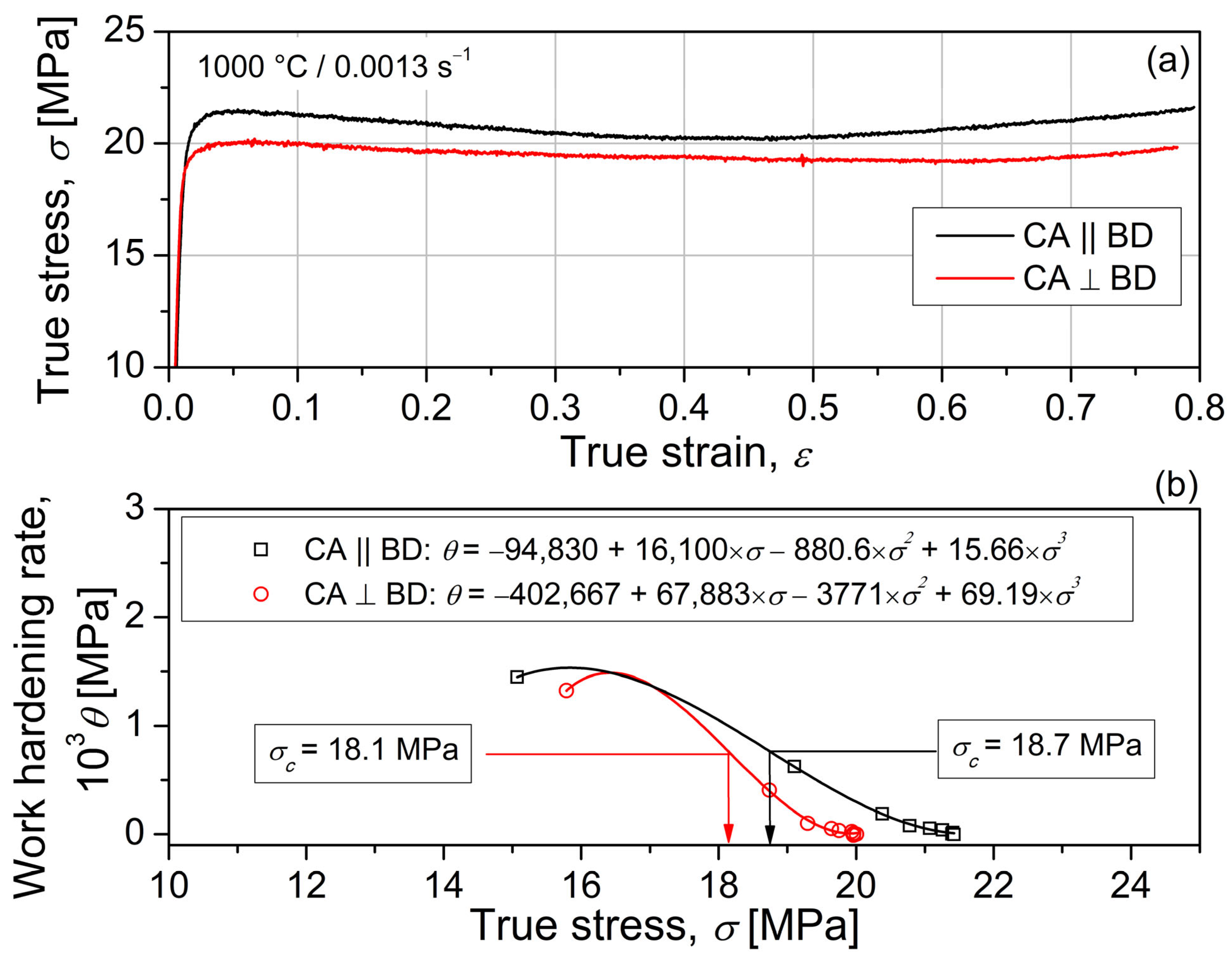
  • The stress–strain curves revealed a broad flow stress peak followed by a slight decrease, which is typical for DRX in conventional BCC metals.
  • A negligible dependence of the flow stress behavior on the compression direction was observed. The samples compressed parallel and perpendicular to the building direction revealed comparable flow stress–strain curves and work hardening behavior under the tested hot deformation conditions. The DRX initiated at a stress of 18.7 MPa for the sample compressed parallel to the BD, corresponding to a true strain of 0.011, and at 18.1 MPa for the samples compressed normal to the BD, which corresponded to a true strain of 0.010.
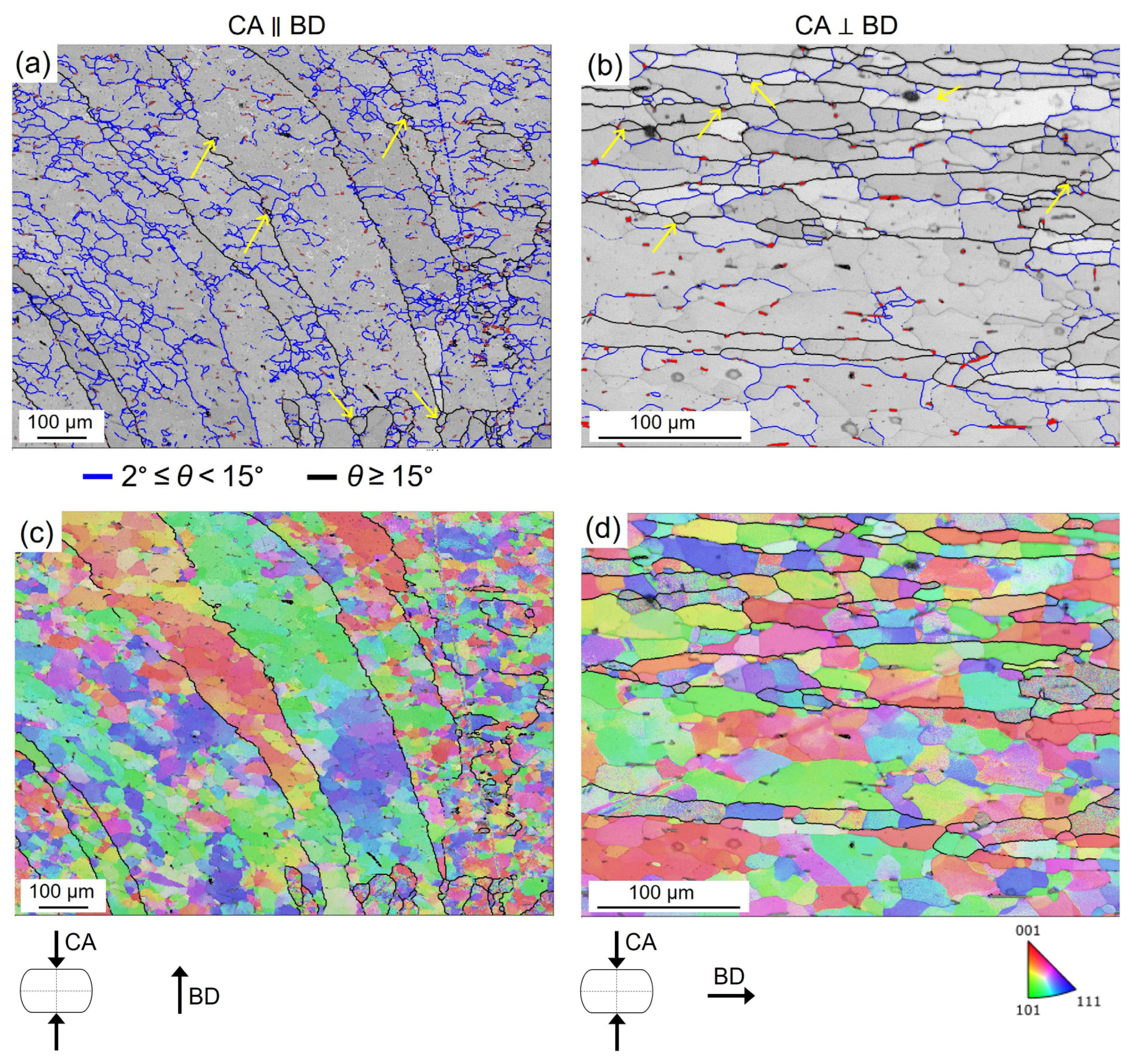
  • The relatively coarse and elongated microstructure of the as-LPBF builds refined significantly after hot working. The microstructure of the deformed samples consisted deformed grains fragmented by sub-grains bounded by low-angle boundaries independent of the compression axis, indicating the occurrence of dynamic recovery during hot deformation.
  • Some small equiaxed grains were formed at the original grain boundaries of the deformed specimens, suggesting the occurrence of dynamic recrystallization during hot deformation.
  • Most of the pores in the as-built-LPBF samples were closed after hot compression, particularly in the central region of the deformed specimens, confirming the benefits of hot working as a post-processing tool to reduce defects and refine the microstructure of the AM samples.

Author Contributions

Conceptualization, A.E.; Methodology, A.E.; Investigation, A.E., S.B., F.J. and M.T.; writing—original draft preparation, A.E.; writing—review and editing, A.E. and S.W.; Supervision, A.E. and S.W. All authors have read and agreed to the published version of the manuscript.

Funding

This research received no external funding.

Data Availability Statement

The data are available upon request from the corresponding authors.

Acknowledgments

A. Emdadi acknowledges Fachgebiet Hybride Fertigung (BTU Cottbus-Senftenberg) for LPBF operations and compression tests.

Conflicts of Interest

The authors declare that they have no known competing financial interest or personal relationships that could have appeared to influence the work reported in this paper.

References

  1. Morris, D.G.; Muñoz-Morris, M.A. Recent Developments Toward the Application of Iron Aluminides in Fossil Fuel Technologies. Adv. Eng. Mater. 2011, 13, 43–47. [Google Scholar] [CrossRef]
  2. Zamanzade, M.; Barnoush, A.; Motz, C. A Review on the Properties of Iron Aluminide Intermetallics. Crystals 2016, 6, 10. [Google Scholar] [CrossRef] [Green Version]
  3. Palm, M.; Stein, F.; Dehm, G. Iron Aluminides. Annu. Rev. Mater. Res. 2019, 49, 297–326. [Google Scholar] [CrossRef]
  4. Palm, M. Fe–Al materials for structural applications at high temperatures: Current research at MPIE. IJMR 2009, 100, 277–287. [Google Scholar] [CrossRef]
  5. Prokopčáková, P.; Švec, M.; Palm, M. Microstructural evolution and creep of Fe–Al–Ta alloys. IJMR 2016, 107, 396–405. [Google Scholar] [CrossRef]
  6. Risanti, D.D.; Sauthoff, G. Microstructures and mechanical properties of Fe–Al–Ta alloys with strengthening Laves phase. Intermetallics 2011, 19, 1727–1736. [Google Scholar] [CrossRef]
  7. Risanti, D.D.; Sauthoff, G. Iron—Aluminium-Base Alloys with Strengthening Laves Phase for Structural Applications at High Temperatures. Mater. Sci. Forum 2005, 475–479, 865–868. [Google Scholar] [CrossRef]
  8. Bahadur, A. Enhancement of high temperature strength and room temperature ductility of iron aluminides by alloying. Mater. Sci. Technol. 2003, 19, 1627–1634. [Google Scholar] [CrossRef]
  9. Emdadi, A.; Sizova, I.; Bambach, M.; Hecht, U. Hot deformation behavior of a spark plasma sintered Fe-25Al-1.5Ta alloy with strengthening Laves phase. Intermetallics 2019, 109, 123–134. [Google Scholar] [CrossRef]
  10. Emdadi, A. High-Temperature Deformation Behavior of Intermetallic Titanium and Iron Aluminides Produced by Spark Plasma Sintering, 1st ed.; Shaker: Düren, Germany, 2021; ISBN 978-3-8440-7933-3. [Google Scholar]
  11. Emdadi, A.; Sizova, I.; Stryzhyboroda, O.; Hecht, U.; Buhl, J.; Bambach, M. Hot Workability of a Spark Plasma Sintered Intermetallic Iron Aluminide Alloy Above and Below the Order-disorder Transition Temperature. Procedia Manuf. 2020, 47, 1281–1287. [Google Scholar] [CrossRef]
  12. Stein, F.; Leineweber, A. Laves phases: A review of their functional and structural applications and an improved fundamental understanding of stability and properties. J. Mater. Sci. 2021, 56, 5321–5427. [Google Scholar] [CrossRef]
  13. Emdadi, A.; Bolz, S.; Buhl, J.; Weiß, S.; Bambach, M. Laser Powder Bed Fusion Additive Manufacturing of Fe3Al-1.5Ta Iron Aluminide with Strengthening Laves Phase. Metals 2022, 12, 997. [Google Scholar] [CrossRef]
  14. Tan, Q.; Zhu, G.; Zhou, W.; Tian, Y.; Zhang, L.; Dong, A.; Shu, D.; Sun, B. Precipitation, transformation, and coarsening of carbides in a high-carbon Ni-based superalloy during selective laser melting and hot isostatic pressing processes. J. Alloys Compd. 2022, 913, 165196. [Google Scholar] [CrossRef]
  15. Pruncu, C.I.; Hopper, C.; Hooper, P.A.; Tan, Z.; Zhu, H.; Lin, J.; Jiang, J. Study of the Effects of Hot Forging on the Additively Manufactured Stainless Steel Preforms. J. Manuf. Process. 2020, 57, 668–676. [Google Scholar] [CrossRef]
  16. Sizova, I.; Sviridov, A.; Bambach, M.; Eisentraut, M.; Hemes, S.; Hecht, U.; Marquardt, A.; Leyens, C. A study on hot-working as alternative post-processing method for titanium aluminides built by laser powder bed fusion and electron beam melting. J. Mater. Process. Technol. 2021, 291, 117024. [Google Scholar] [CrossRef]
  17. Sizova, I.; Bambach, M. Hot workability and microstructure evolution of pre-forms for forgings produced by additive manufacturing. J. Mater. Process. Technol. 2018, 256, 154–159. [Google Scholar] [CrossRef]
  18. Fu, Y.; Zhang, H.; Wang, G.; Wang, H. Investigation of mechanical properties for hybrid deposition and micro-rolling of bainite steel. J. Mater. Process. Technol. 2017, 250, 220–227. [Google Scholar] [CrossRef]
  19. Motallebi, R.; Savaedi, Z.; Mirzadeh, H. Additive manufacturing–A review of hot deformation behavior and constitutive modeling of flow stress. Curr. Opin. Solid State Mater. Sci. 2022, 26, 100992. [Google Scholar] [CrossRef]
  20. Bambach, M.; Sizova, I.; Emdadi, A. Development of a processing route for Ti-6Al-4V forgings based on preforms made by selective laser melting. J. Manuf. Process. 2019, 37, 150–158. [Google Scholar] [CrossRef]
  21. Di Serio, E.T.; Duperray, L.; Perrier, F.; Desrayaud, C. Method for the Production of Parts Made from Metal or Metal Matrix Composite and Resulting from Additive Manufacturing Followed by an Operation Involving the Forging of Said Parts. U.S. Patent WO/2015/166167, 5 November 2015. [Google Scholar]
  22. Roegner, E.V.; Colvin, E.L.; Mueller, L.N.; Rioja, R.J.; Bodily, B.H. Methods for Producing Forged Products and Other Worked Products. U.S. Patent WO/2015/006447, 15 January 2015. [Google Scholar]
  23. Bambach, M.; Sizova, I.; Sydow, B.; Hemes, S.; Meiners, F. Hybrid manufacturing of components from Ti-6Al-4V by metal forming and wire-arc additive manufacturing. J. Mater. Process. Technol. 2020, 282, 116689. [Google Scholar] [CrossRef]
  24. Bambach, M.; Sizova, I.; Szyndler, J.; Bennett, J.; Hyatt, G.; Cao, J.; Papke, T.; Merklein, M. On the hot deformation behavior of Ti-6Al-4V made by additive manufacturing. J. Mater. Process. Technol. 2021, 288, 116840. [Google Scholar] [CrossRef]
  25. Tao, P.; Zhong, J.; Li, H.; Hu, Q.; Gong, S.; Xu, Q. Microstructure, Mechanical Properties, and Constitutive Models for Ti–6Al–4V Alloy Fabricated by Selective Laser Melting (SLM). Metals 2019, 9, 447. [Google Scholar] [CrossRef] [Green Version]
  26. Maurya, A.K.; Yeom, J.-T.; Kang, S.W.; Park, C.H.; Hong, J.-K.; Reddy, N.S. Optimization of hybrid manufacturing process combining forging and wire-arc additive manufactured Ti-6Al-4V through hot deformation characterization. J. Alloys Compd. 2022, 894, 162453. [Google Scholar] [CrossRef]
  27. Bambach, M.; Sizova, I.; Silze, F.; Schnick, M. Hot workability and microstructure evolution of the nickel-based superalloy Inconel 718 produced by laser metal deposition. J. Alloys Compd. 2018, 740, 278–287. [Google Scholar] [CrossRef]
  28. Lan, B.; Wang, Y.; Liu, Y.; Hooper, P.; Hopper, C.; Zhang, G.; Zhang, X.; Jiang, J. The influence of microstructural anisotropy on the hot deformation of wire arc additive manufactured (WAAM) Inconel 718. Mater. Sci. Eng. A 2021, 823, 141733. [Google Scholar] [CrossRef]
  29. Mostafa, A.; Shahriari, D.; Rubio, I.P.; Brailovski, V.; Jahazi, M.; Medraj, M. Hot compression behavior and microstructure of selectively laser-melted IN718 alloy. Int. J. Adv. Manuf. Technol. 2018, 642, 279. [Google Scholar] [CrossRef]
  30. Jinoop, A.N.; Anil Kumar, V.; Paul, C.P.; Ranjan, R.; Bindra, K.S. Hot deformation behavior of Hastelloy-X preforms built using directed energy deposition based laser additive manufacturing. Mater. Lett. 2020, 270, 127737. [Google Scholar] [CrossRef]
  31. AlMangour, B.; Kim, Y.-K.; Grzesiak, D.; Lee, K.-A. Novel TiB2-reinforced 316L stainless steel nanocomposites with excellent room- and high-temperature yield strength developed by additive manufacturing. Compos. Part B Eng. 2019, 156, 51–63. [Google Scholar] [CrossRef]
  32. Liu, Y.; Zhang, C.; Wang, Y.; Xu, X.; Zhu, H.; Jiang, J. Reveal the hot deformation behaviour and microstructure evolution in additively manufactured 316L stainless steel. Mater. Sci. Eng. A 2022, 861, 144290. [Google Scholar] [CrossRef]
  33. Zhou, Y.; Lin, X.; Kang, N.; Wang, Z.; Tan, H.; Huang, W. Hot deformation induced microstructural evolution in local-heterogeneous wire + arc additive manufactured 2219 Al alloy. J. Alloys Compd. 2021, 865, 158949. [Google Scholar] [CrossRef]
  34. Dai, S.; Deng, Z.C.; Yu, Y.J.; Zhu, K.Y. Microstructure and constitutive model for flow behavior of AlSi10Mg by Selective Laser Melting. Mater. Sci. Eng. A 2021, 814, 141157. [Google Scholar] [CrossRef]
  35. Emdadi, A.; Weiß, S. A Comparative Study of Microstructure and Hot Deformability of a Fe–Al–Ta Iron Aluminide Prepared via Additive Manufacturing and Conventional Casting. Crystals 2022, 12, 1709. [Google Scholar] [CrossRef]
  36. Moszner, F.; Peng, J.; Suutala, J.; Jasnau, U.; Damani, M.; Palm, M. Application of Iron Aluminides in the Combustion Chamber of Large Bore 2-Stroke Marine Engines. Metals 2019, 9, 847. [Google Scholar] [CrossRef] [Green Version]
  37. Hanus, P.; Bartsch, E.; Palm, M.; Krein, R.; Bauer-Partenheimer, K.; Janschek, P. Mechanical properties of a forged Fe–25Al–2Ta steam turbine blade. Intermetallics 2010, 18, 1379–1384. [Google Scholar] [CrossRef]
  38. Wright, S.I.; Nowell, M.M.; Field, D.P. A review of strain analysis using electron backscatter diffraction. Microsc. Microanal. 2011, 17, 316–329. [Google Scholar] [CrossRef] [PubMed]
  39. Rolink, G.; Vogt, S.; Senčekova, L.; Weisheit, A.; Poprawe, R.; Palm, M. Laser metal deposition and selective laser melting of Fe–28 at.% Al. J. Mater. Res. 2014, 29, 2036–2043. [Google Scholar] [CrossRef]
  40. Pütz, R.D.; Zander, D. High temperature oxidation mechanisms of grain refined Fe-25Al-1.5Ta(+TaC/+(Ta,Nb)C) iron aluminides at 700 °C in air. Corros. Sci. 2022, 198, 110149. [Google Scholar] [CrossRef]
  41. Risanti, D.D.; Sauthoff, G. Strengthening of iron aluminide alloys by atomic ordering and Laves phase precipitation for high-temperature applications. Intermetallics 2005, 13, 1313–1321. [Google Scholar] [CrossRef]
  42. Tsuji, N.; Matsubara, Y.; Saito, Y. Dynamic recrystallization of ferrite in interstitial free steel. Scr. Mater. 1997, 37, 477–484. [Google Scholar] [CrossRef]
  43. Najafizadeh, A.; Jonas, J.J. Predicting the Critical Stress for Initiation of Dynamic Recrystallization. Mater. Sci. Eng. A 2006, 46, 1679–1684. [Google Scholar] [CrossRef] [Green Version]
  44. Humphreys, F.J.; Hatherly, M. Recrystallization and Related Annealing Phenomena; Elsevier: Amsterdam, The Netherlands, 2012; ISBN 008098388X. [Google Scholar]
  45. Voyzelle, B.; Boyd, J.D. High-temperature deformation behaviour of Fe3Al. Mater. Sci. Eng. A 1998, 258, 243–248. [Google Scholar] [CrossRef]
  46. Łyszkowski, R.; Bystrzycki, J. Hot deformation and processing maps of an Fe3Al intermetallic alloy. Intermetallics 2006, 14, 1231–1237. [Google Scholar] [CrossRef]
  47. Sundar, R.S.; Baligidad, R.G.; Prasad, Y.V.R.K.; Sastry, D.H. Processing of iron aluminides. Mater. Sci. Eng. A 1998, 258, 219–228. [Google Scholar] [CrossRef]
Figure 1. Room-temperature XRD pattern (a) and a typical BSE-SEM microstructure of the cross-section of cylindrical Fe-25Al-1.5Ta specimens produced by LPBF (b,c). The arrows in a higher magnification image in (c) indicate a few pores. BD and SD refer to the building and scanning direction. The small white-contrast regions are (Fe, Al)2Ta C14 Laves phase precipitates formed along the matrix grain boundaries and within the grains. The sample was printed using P = 250 W and vs = 1000 mm/s.
Crystals 13 00627 g001
Figure 2. True stress–strain curves (a) and strain-hardening rate (θ) versus flow stress (σ) up to the peak stress (b) of LPBF specimens hot compressed at 1000 °C up to a true strain of 0.8 with a strain rate of 0.0013 s−1 in different directions to the BD. The rise in flow stress after a steady state is due to the dominance of friction and bulging of the specimens at higher strains. The θσ curves were fitted by a third-order polynomial, and the relationships between θ and σ were given. The CA and BD refer to the compression axis and building direction in the LPBF process.
Crystals 13 00627 g002
Figure 3. Typical SEM-BSE micrographs of the LPBF-fabricated Fe-25Al-1.5Ta specimen hot compressed at 1000 °C/0.0013 s−1 up to a true strain of 0.8 parallel to the BD. The micrograph in (b) shows a high-resolution image of the central region of the specimen marked by a white rectangle in (a). The white-contrast regions represent (Fe, Al)2Ta C14 Laves phase precipitate particles. CA and BD refer to the compression axis and building direction in the LPBF process, respectively. CA is parallel to the BD.
Crystals 13 00627 g003
Figure 4. EBSD grain boundary misorientation maps superimposed with image quality (IQ) maps (a,b) and GROD-axis maps (c,d) for the LPBF-fabricated builds subjected to hot compression at 1000 °C/0.0013 s−1 up to a true strain of 0.8. CA and BD refer to compression axis and building direction, respectively. CA was either parallel (a,c) or perpendicular (b,d) to the BD. The blue and black lines mark low-angle grain boundaries with misorientations (θ), 2° ≤ θ < 15° and high-angle grain boundaries with θ ≥ 15°, respectively. Small red regions in (a,b) exhibit C14 Laves phase precipitate particles. The arrows in (a,b) indicate a few small, equiaxed grains formed at the pre-existing grain boundaries.
Crystals 13 00627 g004
Table 1. Critical stress and strain values for the onset of DRX in the samples deformed in different directions to the BD and their relationships with peak stress and strain (σc/εc—critical stress and strain for the initiation of DRX, σp/εp—peak stress and strain). CA and BD are the compression axis and building direction during LPBF. The measurement accuracy is around ± 0.3 MPa.
Compression Axis with Respect to the BDCritical Stress and Strain Values for DRX OnsetPeak Stress and Strain ValuesRelationships
Parallel to the BD (CA ∥ BD)σc = 18.7
εc = 0.011
σp = 21.4
εp = 0.04
σc = 0.87 σp
εc = 0.27 εc
Normal to the BD (CA ⊥ BD) σc = 18.1
εc = 0.010
σp = 20.1
εp = 0.06
σc = 0.90 σp
εc = 0.17 εc
Disclaimer/Publisher’s Note: The statements, opinions and data contained in all publications are solely those of the individual author(s) and contributor(s) and not of MDPI and/or the editor(s). MDPI and/or the editor(s) disclaim responsibility for any injury to people or property resulting from any ideas, methods, instructions or products referred to in the content.

