Article

Pulsed and Static Magnetic Field Influence on Metallic Alloys during Solidification

Institute of Physics, University of Latvia, Miera Street 32, LV-2169 Salaspils, Latvia
*
Author to whom correspondence should be addressed.
Crystals 2023, 13(2), 259; https://doi.org/10.3390/cryst13020259
Submission received: 29 December 2022 / Revised: 20 January 2023 / Accepted: 31 January 2023 / Published: 2 February 2023
(This article belongs to the Special Issue Phase Transition in External Fields)

Abstract

:
Electromagnetic methods can be used to affect the solidification of metallic alloys. Combined alternating and static (DC) magnetic fields can induce pressure waves in liquid metals in a contactless manner, refining grain structure, preventing component segregation, and dispersing added particles. Here, the possibility of using a pulsed magnetic field in combination with a DC magnetic field to improve the solidification structure of metals is investigated. This enables achieving higher pressure amplitude and liquid movement within the whole crucible volume at the same power consumption. This can be a prospective way to achieve a fine-grained and a more homogeneous microstructure of metallic alloys as well as disperse added particles. In this work, analytical description of the phenomena and numerical modeling of the pressure amplitude and melt motion has been performed. A series of experiments have been carried out to demonstrate the effect of such interaction on the solidified metal microstructure. It is found that a combination of pulsed and DC magnetic fields creates strong compression and expansion of the liquid metal. Metals solidified under such interaction exhibit finer grain structure in Sn-Pb alloy and improved TiB2 particle distribution in 6061 aluminum alloy.

1. Introduction

Fine and homogeneous grain structure can improve an alloy’s mechanical properties, such as tensile strength, yield strength, etc. The most common grain refinement methods are: (a) stirring during solidification; (b) addition of a grain refiner to the alloy, for example, TiB2 particle-rich master alloy to aluminum alloys; (c) increase of the cooling rate. In this study, we investigate combined pulsed magnetic field (PMF) and static (BDC) magnetic field interaction for two potential applications—melt stirring and grain refining.
Stirring for improving microstructure can be generated by using mechanical [1] or electromagnetic stirrers [2,3]. Stirring in the melt modifies the solidification structures by penetrating the mushy zone, remelting the dendrite arms, and preventing large, oriented dendrite growth. The reduced local thermal gradient leads to favoring columnar to equiaxed transition [4,5]. Compared to continuous electromagnetic stirring by traveling or rotating magnetic fields, PMF can generate Lorentz force in the melt with significantly higher amplitude, while the Joule heating in the melt is much lower. PMF treatment in metallurgy has been studied for various applications. It can be beneficial to reduce particle cluster formation, homogenize temperature distribution, and reduce grain size. Zhao [6] has shown that PMF with intensity up to 154 mT and pulse period 20 ms can significantly refine grain structure of aluminum. The proposed physical mechanism for grain refinement is that the liquid phase has higher resistivity than the solid phase, which leads to a higher temperature rise in the liquid phase due to Joule heating, dendrite breaking, and remelting during the magnetic interaction. As a result, the average grain size is significantly reduced. Similar electromagnetic treatment to obtain fine, equiaxed grains has been shown for superalloy K417 and IN718 [7,8]. Bao [9] has shown that pulsed magnetic field treatment before the direct chill casting process reduces cluster formation in Al-Si-Mg-Cu-Ni alloy and refines the dendrite structure. Zhang [10] obtained improvement of mechanical properties, such as ultimate tensile strength (UTS) by 18%, yield strength (YS) by 16%, and elongation by 142% in A357 alloy. The peak magnetic flux density was 174 mT, which led to 0.12 N/cm3 transient Lorentz force on the surface and ~0.01 N/cm3 in the action region during the peak. Another study shows that a PMF improves carbon fiber infiltration processes in aluminum alloys [11].
Another possible application of the developed combined PMF and B
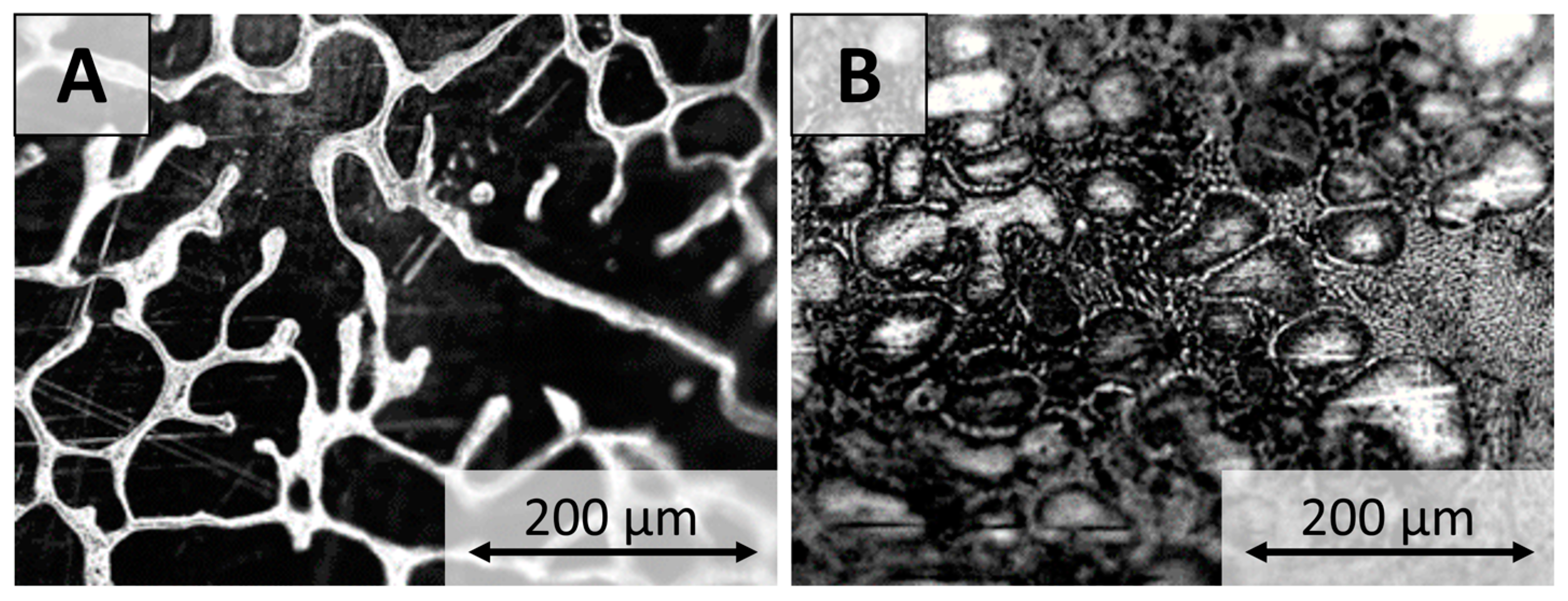
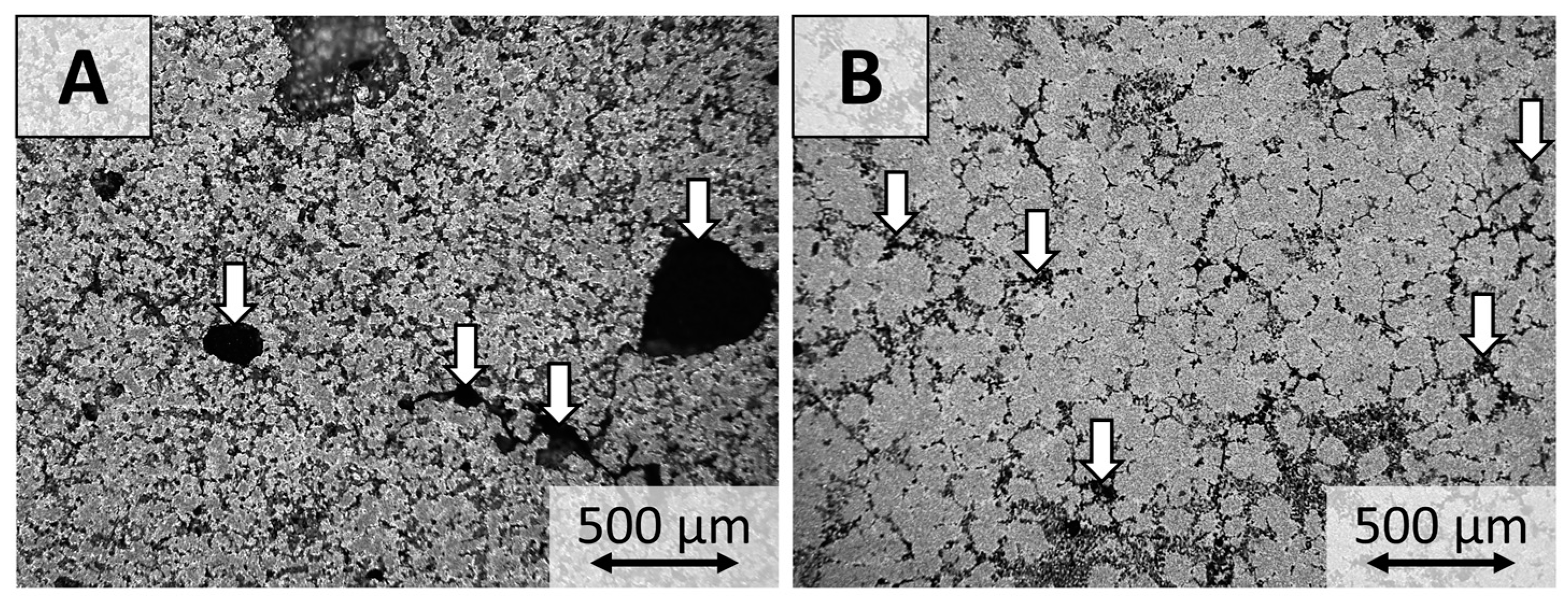
DC interaction is the metal matrix composite production with electromagnetic methods. Metal matrix composites belong to a material class where reinforcement particles are introduced into the metal matrix to improve material properties such as mechanical, thermal, corrosion, etc. Reinforcement can be shaped as particles, fibers, or flakes. The liquid or metallurgical manufacturing route for MMC production is beneficial due to low raw material costs and process scalability but is challenging due to low wettability of the particles with metal alloys. If particles are successfully introduced into the melt, they tend to agglomerate [12,13]. Mechanical sound generation into the melt can initiate cavitation, which has shown to improve particle distribution. Authors previously proposed to generate similar pressure oscillations with superimposed alternating and static magnetic fields, which could be a contactless alternative to mechanical ultrasound [14]. Cavitation bubble collapses are believed to be the mechanism for particle agglomerate dispersion. Maximum induced pressure from the BAC and BDC magnetic field system was able to reach cavitation regime, but the melt volume was limited. By using a PMF, energy can be accumulated in the capacitors and used for short but high intensity pressure oscillations in systems with larger melt volume. It is still under research if there is a difference between cavitation threshold values in alternating magnetic fields and PMF. Cavitation threshold for liquid metals is not well studied and might vary depending on alloy composition, system geometry, ambient pressure, and other parameters [15,16].
In this work, processing of the combined PMF and static magnetic field (BDC) is presented for two possible applications—first, to improve the alloy grain structure of the metallic alloys and, second, for particle agglomerate distribution in the metal matrix composite materials.
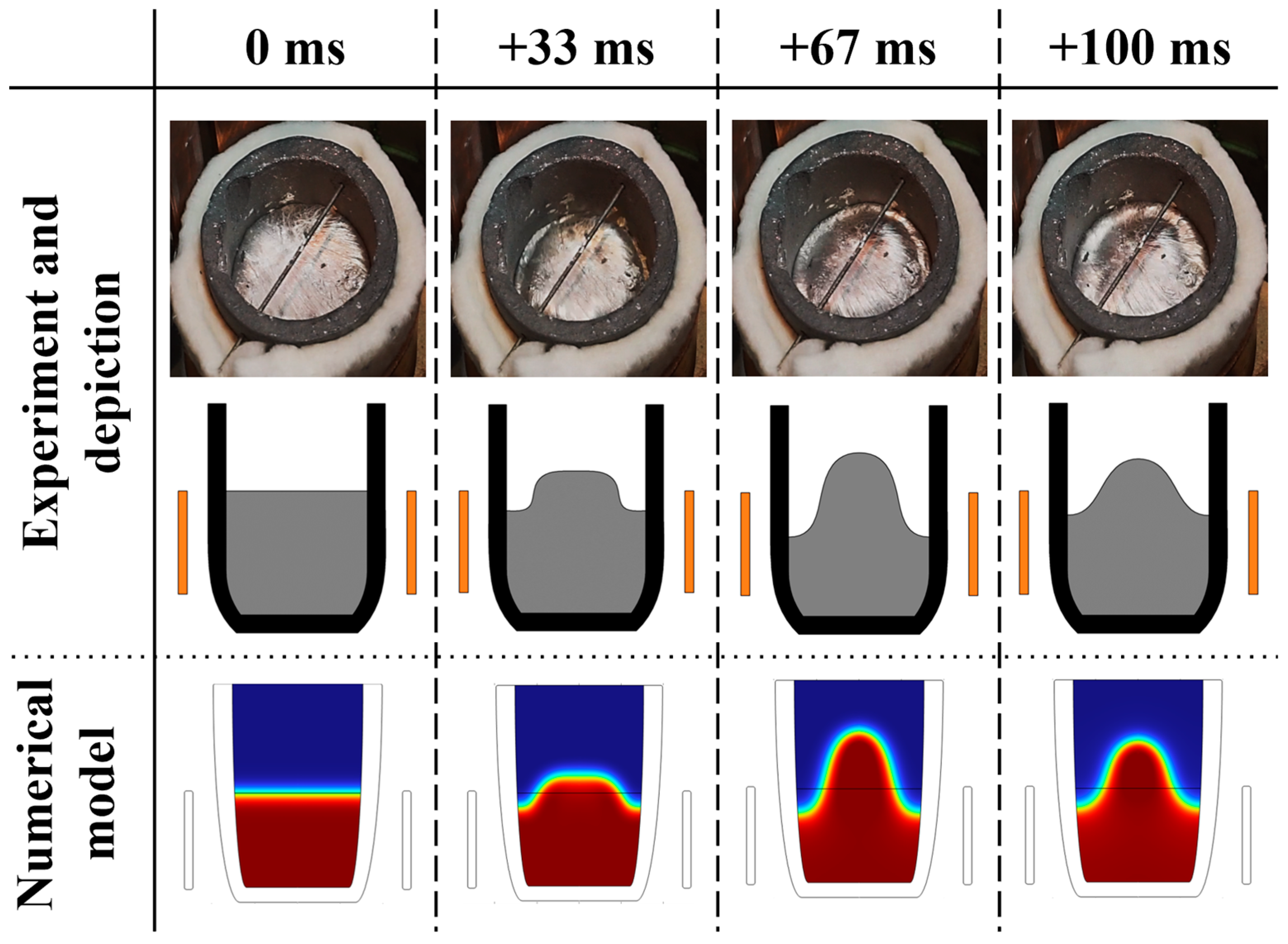
The developed pulse system creates an underdamped PMF with an intensity of up to 500 mT and an oscillation period of 1 ms. Such single pulse interaction with the liquid aluminum inside a crucible causes very intense melt surface deformations and even splashing.
If an external static magnetic field (BDC) is co-applied to the pulsed magnetic field, the induced Lorentz force amplitude is significantly increased, but the melt flow is strongly damped, which can be observed as a much smaller free surface deformation. The combination of PMF and BDC is a new, promising method for metallurgical applications and is still under research. Hua [17] studied changes in microstructure in Sn-Pb alloy after alloy solidification in a combined PMF and BDC magnetic field focusing on the microstructure changes; however, electromagnetic interaction and magnetohydrodynamic (MHD) effects were not discussed.
Here, the description of the magnetic field interaction, induced force and pressure distribution, and other MHD effects are addressed. PMF-generated Lorentz force and velocity distribution without free surface has been numerically studied before [18,19]. We present numerical results from the combined PMF and BDC with free surface deformations, thus allowing the liquid metal to move freely during the pulse. Experimentally, the impact of the EM treatment on the microstructure is studied with Sn-Pb alloy, while the impact on particle distribution is studied with 6061 aluminum alloy with TiB2 particles. For the metal matrix composite application, combined PMF and BDC field interaction is studied for the first time. Such treatment can be advantageous due to the high-pressure amplitude and avoiding liquid metal splashing.

2. Experimental Setup

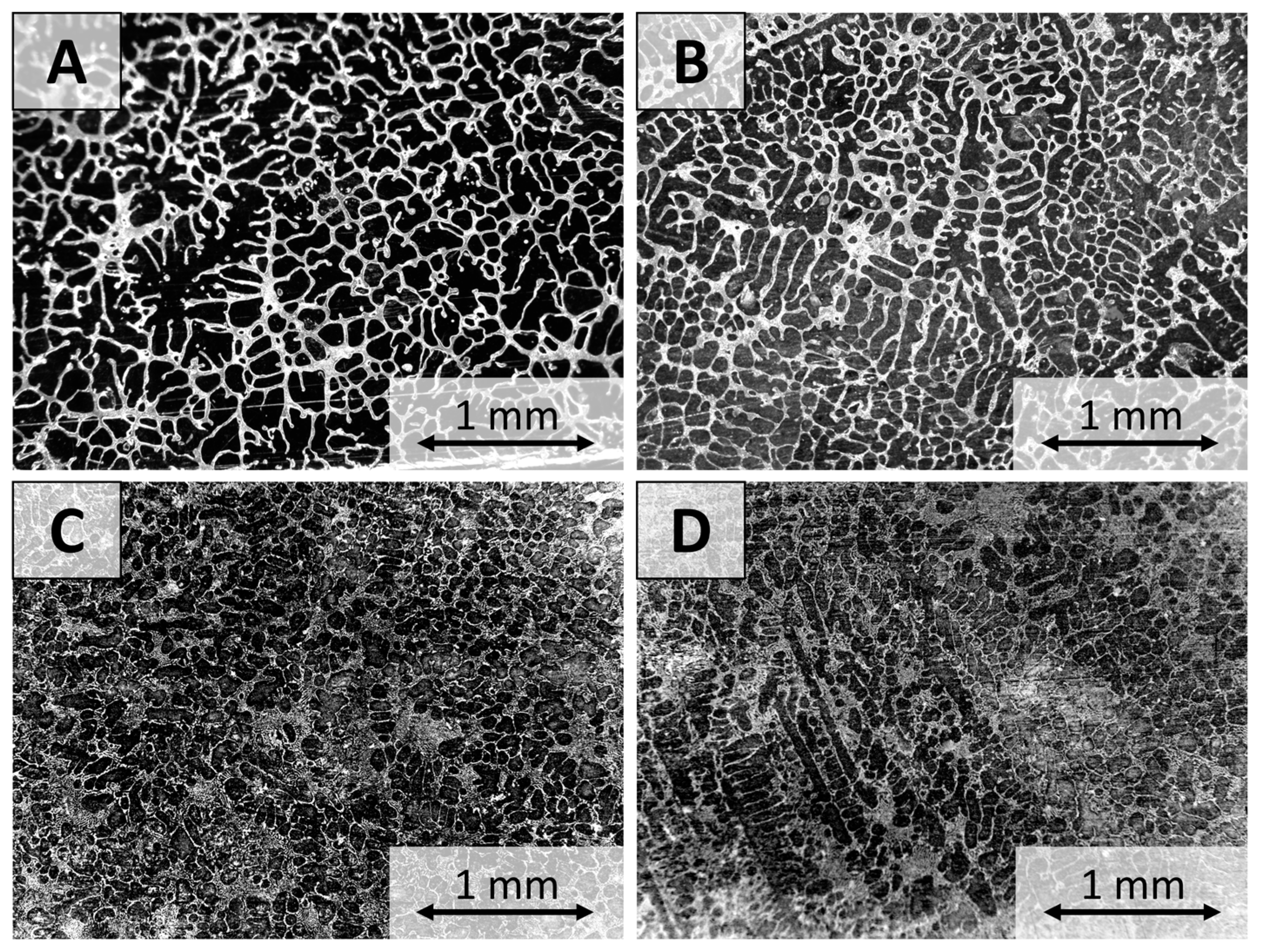
An experimental system for the use of a combined PMF and BDC magnetic field has been developed and experimentally tested. For grain refinement experiments, Sn-10%wt.Pb alloy was used, and for particle dispersion experiments 6061 aluminum alloy was used.
The principal scheme of the experimental setup is shown in 
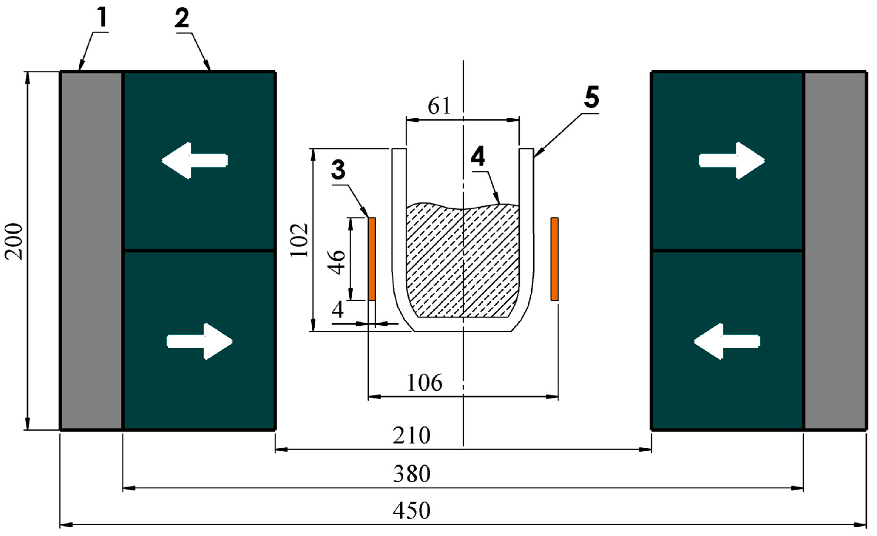
Figure 1. The experimental system is axially symmetric and consists of a crucible, which is positioned in the center of a single turn copper induction coil. During the experiments, a clay graphite crucible with 95 mm top diameter, 61 mm bottom diameter, and 109 mm height (A2 size Salamander crucible) was used [20]. The crucible in the studied pulse frequency range can be considered as electrically nonconductive and does not shield (affect) the electromagnetic field. The static magnetic field is generated with a permanent magnet system that is assembled from NdFeB N42 magnets and an iron yoke [21]. The permanent magnet system consists of two segment-shaped magnet groups with magnetizations radially inward and outward as shown in Figure 1. This permanent magnet assembly is described in more detail in the previous work by the authors [22]. The static magnetic field direction in the melt region is normal to the melt surface and reaches 0.46 T inside the crucible.
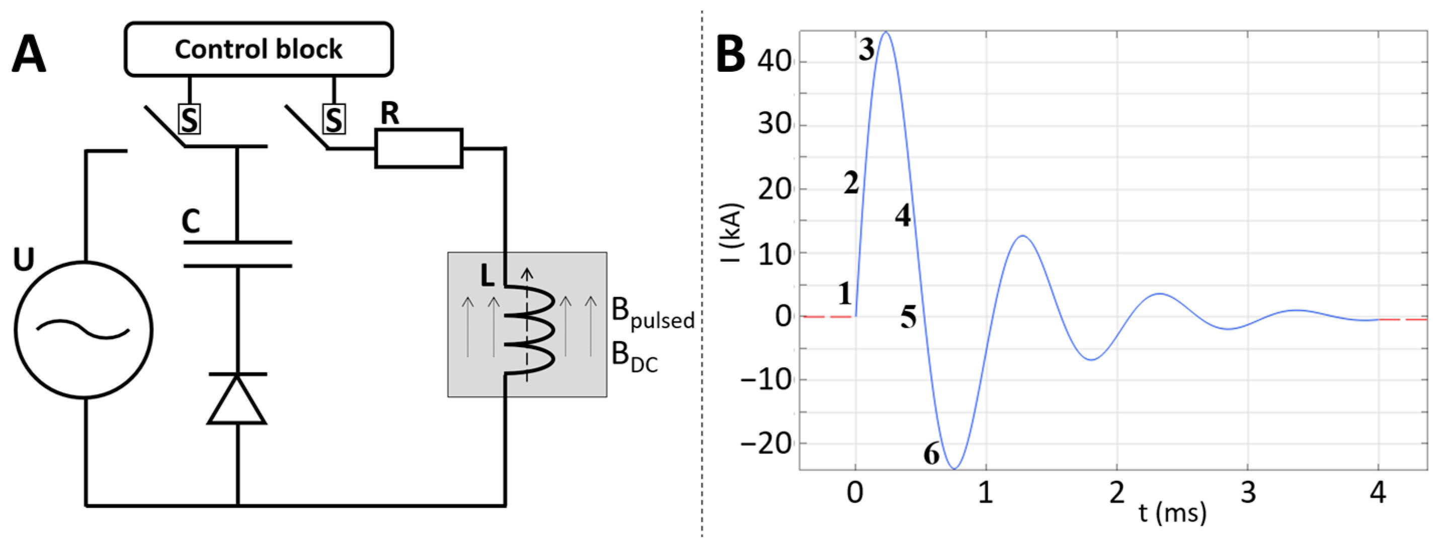
The inductor is fed from the capacitor bank discharge and creates a pulsed magnetic field. The electrical scheme of the pulsed magnetic field source is shown in Figure 2A. PMF is generated by capacitor C discharge through inductor L. The AC transformer U in circuit diodes charges the capacitors. The control block with thyristor switches S and regulates the charging, pause, and discharge time. The measured peak current during the capacitor discharge through the inductor is 40 kA, as shown in 
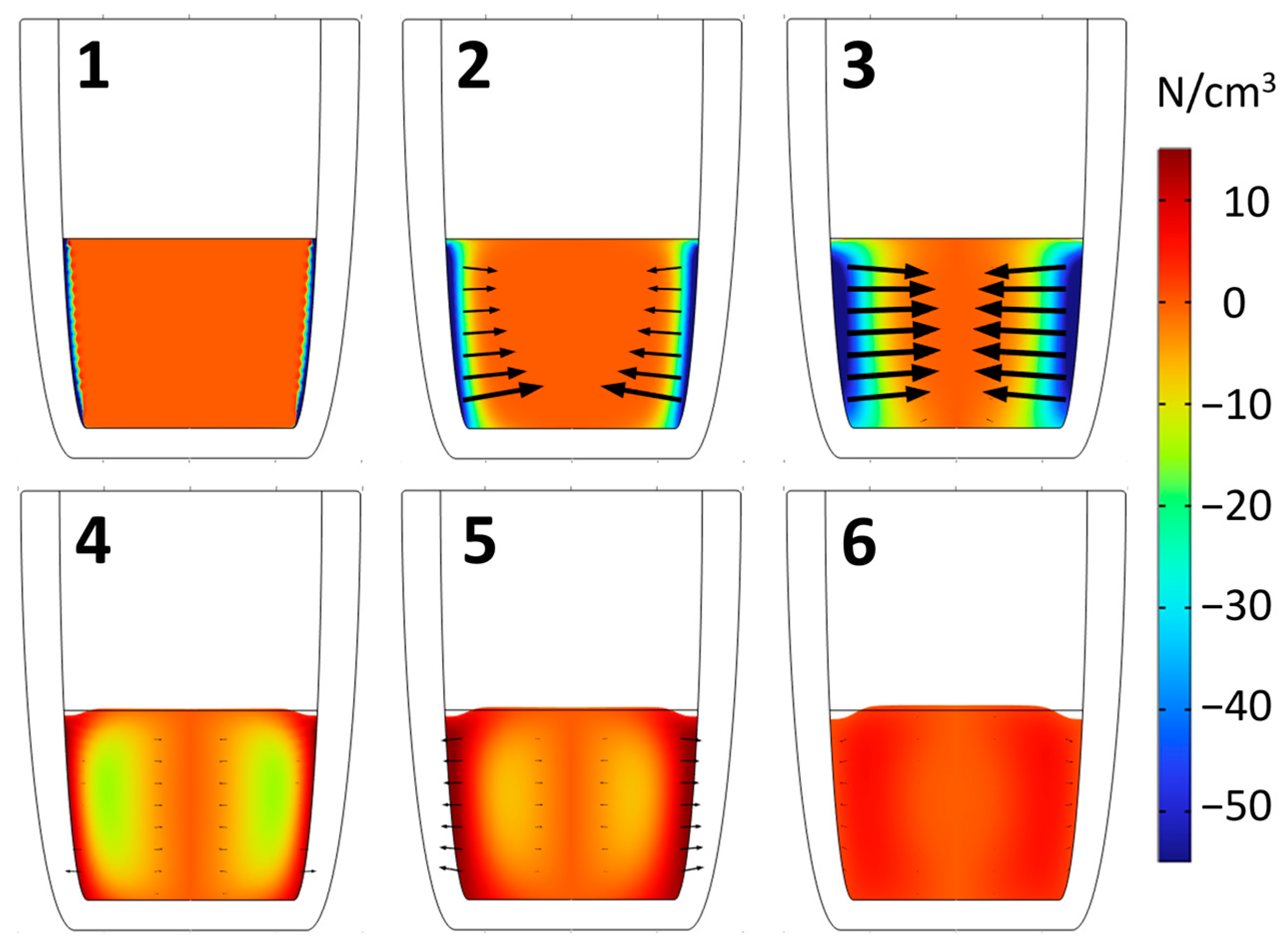
Figure 2B. the pulse oscillation period is 1 ms. The pulse period has been divided into 6 stages of interest: 1-initial, 2-ramp-up, 3-top peak, 4-ramp-down, 5-zero cross, and 6-bottom peak. These stages are later described in the numerical model.
This experimental setup allows changing of PMF intensity with a peak magnetic field value of up to 0.5 T.

3. Theoretical Background

A time-varying magnetic field induces eddy currents in an electrically conducting medium. This current interacts with the magnetic field itself, and they generate an electromagnetic force. In the case of an electrically conducting liquid, this creates a flow and thus a free surface deformation. If a BDC magnetic field is applied simultaneously with a pulsed magnetic field, then strong force pulses are induced in the conducting medium. This can be observed as a vertical jet on the liquid metal free surface during the pulsed interaction.
During the pulsed interaction, static magnetic field has several effects on the liquid metal motion. Due to its interaction with the induced currents from PMF and based on the relative motion between the liquid metal and magnet, BDC can drive or damp the melt flow. This explains why there are fewer distinct free surface deformations with a BDC magnetic field than with a pulsed field only, despite the pressure amplitude inside the conductor being higher than in the case without the BDC magnetic fields. In this study, authors use a capacitor bank, which can be periodically discharged through a single turn inductor. The current amplitude can be regulated with the power source voltage, and the pulse frequency can be adjusted using the controller switches. The measured current in the inductor can be well described by the underdamped oscillation equation:
I = I 0 · e x p - β t · sin ω t
where β = R 2 L is a damping coefficient, frequency ω = ω 0 2 - β 2 , resonant frequency ω 0 = 1 L C . The developed pulse system has the following parameters: C = 50 mF, U = 150 V, L = 1 µH, R = 2.4 mΩ, and I0 = U/R = 60 kA. After substituting all the numbers into Equation (1), the damped oscillation electrical signal becomes (plotted in Figure 2B):
I = 60000 · e x p - 1200 t · sin 6000 t
The physical properties of the materials used in experiments and numerical models are shown in Table 1.
The skin depth in the melt can be estimated as shown in Equation (3). Single pulse penetration of electrically conducting media is described by Grants [23]. The thin skin layer approximation can be used to estimate the pressure in the core of the liquid metal volume.
δ = 1 σ f π μ μ 0
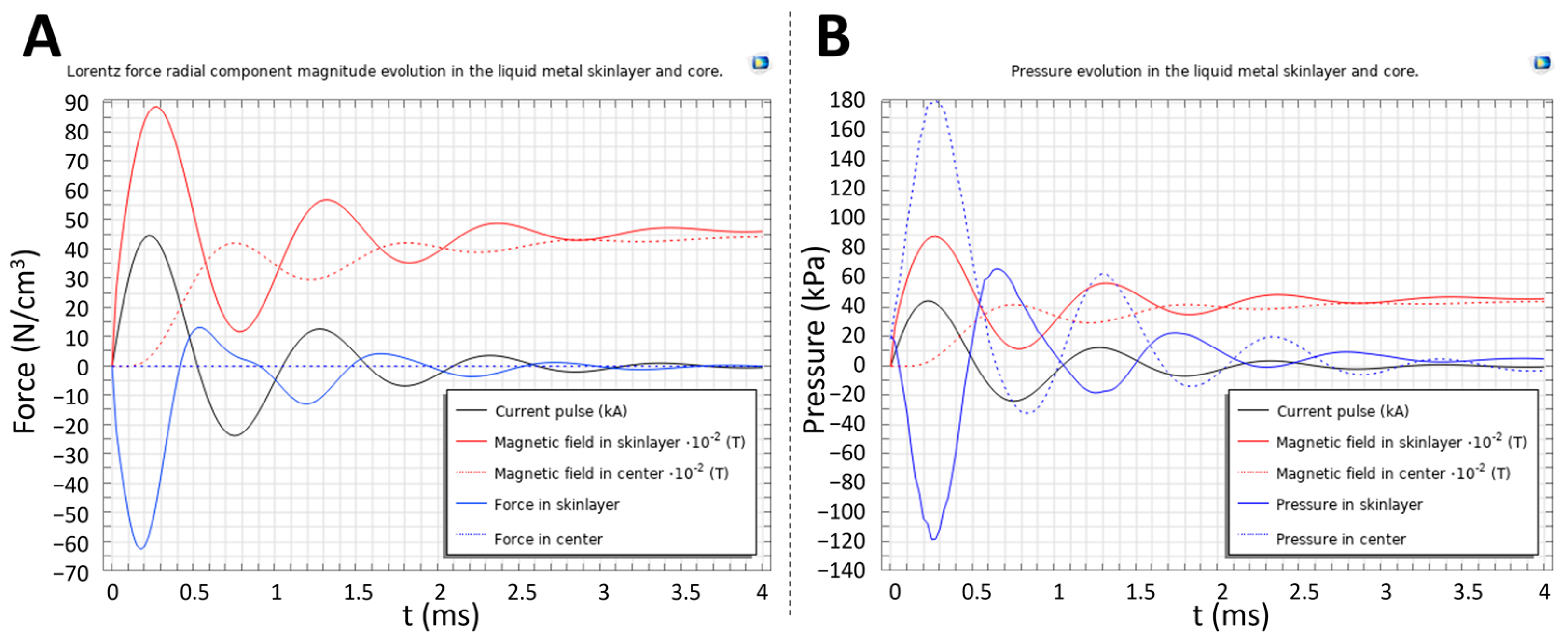
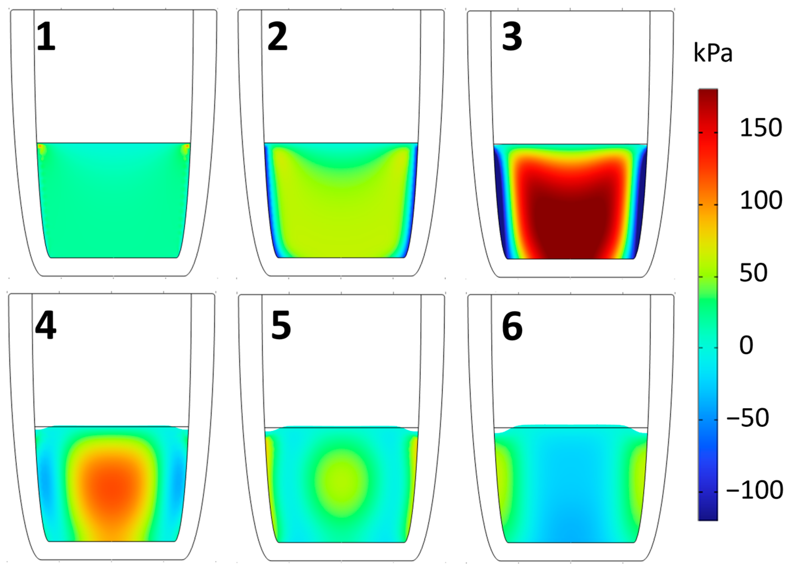
Pressure amplitude in the conducting media can be calculated as an induced current multiplied by BDC magnetic field. Depending on BDC magnetic field direction in the first half period of the pulse, liquid metal is either stretched or compressed. Significant motion is induced in liquid metal, which manifests itself as a jump of the free surface, which is much higher without a BDC magnetic field. Effect is shown in video in supplementary materials. In the melt area, BDC = 0.46 T and is created by the permanent magnet assembly as shown in Figure 1 Magnetic field amplitude during the pulse can be evaluated as B A C = μ 0 I 2 R = 0.5 T . The pressure amplitude from the combined PMF and BDC magnetic fields gives P = B A C B D C + B A C 2 μ 0 = 190 k P a . In this case, the calculated pressure amplitude is comparable to the estimated cavitation threshold reported in the literature, which in pure tin is detected at 120 kPa [14] and 280 kPa [16], and in aluminum 65 kPa [15]. In the thin skin layer approximation, we can assume that all magnetic fields in the center of the conductor are compensated by the eddy currents in the skin layer of the liquid metal. Thus, eddy currents created by the magnetic field should be equal to the external BDC magnetic field:
j = I r δ H R c = 1.5 · 10 7 A m 2 ,
where I is coil current (40 kA), r is crucible radius (3 cm), δ is skin depth (10 mm), H is liquid metal height (4 cm), R c is coil radius (5 cm), and t is half period of the pulse. Velocity of liquid metal and surface deformation can be estimated by balancing the momentum. Momentum is created only in the skin layer, but it moves all the melt volume. Here Lorentz force density f = j × B = 7 · 10 6 N m 3 .
The initial velocity, which is created during the magnetic field pulse, can be estimated from Equation (6) as 60 cm/s:
2 δ f t = ρ v r
v = 2 δ f t ρ r
Such velocity creates surface deformation of h = v2/2 g= 2 cm (SnPb) and 3 cm (Al). Liquid metal gains momentum during the 1 ms pulse and further motion occurs due to inertia. Approximate motion time can be estimated using the assumption that the liquid is in free fall. In this case h = gt2/2, and we obtain a rise time of 3 cm in 75 ms, which is in good agreement with the observation shown in Results section. It can be estimated that a single pulse releases W = CU2/2 = 560 J of energy, part of which goes to heating. Joule heat released in the melt during one pulse can be estimated as:
q = 2 t π r δ H j 2 σ = 9 J .
For a single pulse, only 9 J go toward heating the liquid metal. For higher pulse frequencies, however, this can become a considerable additional heat source and change the solidification time. This can be compensated by the crucible insulation and control of the heat flow through the bottom of the crucible. In the given case, this power is still small, and it was observed that cooling time with and without a pulsed magnetic field is not different.

4. Numerical Model

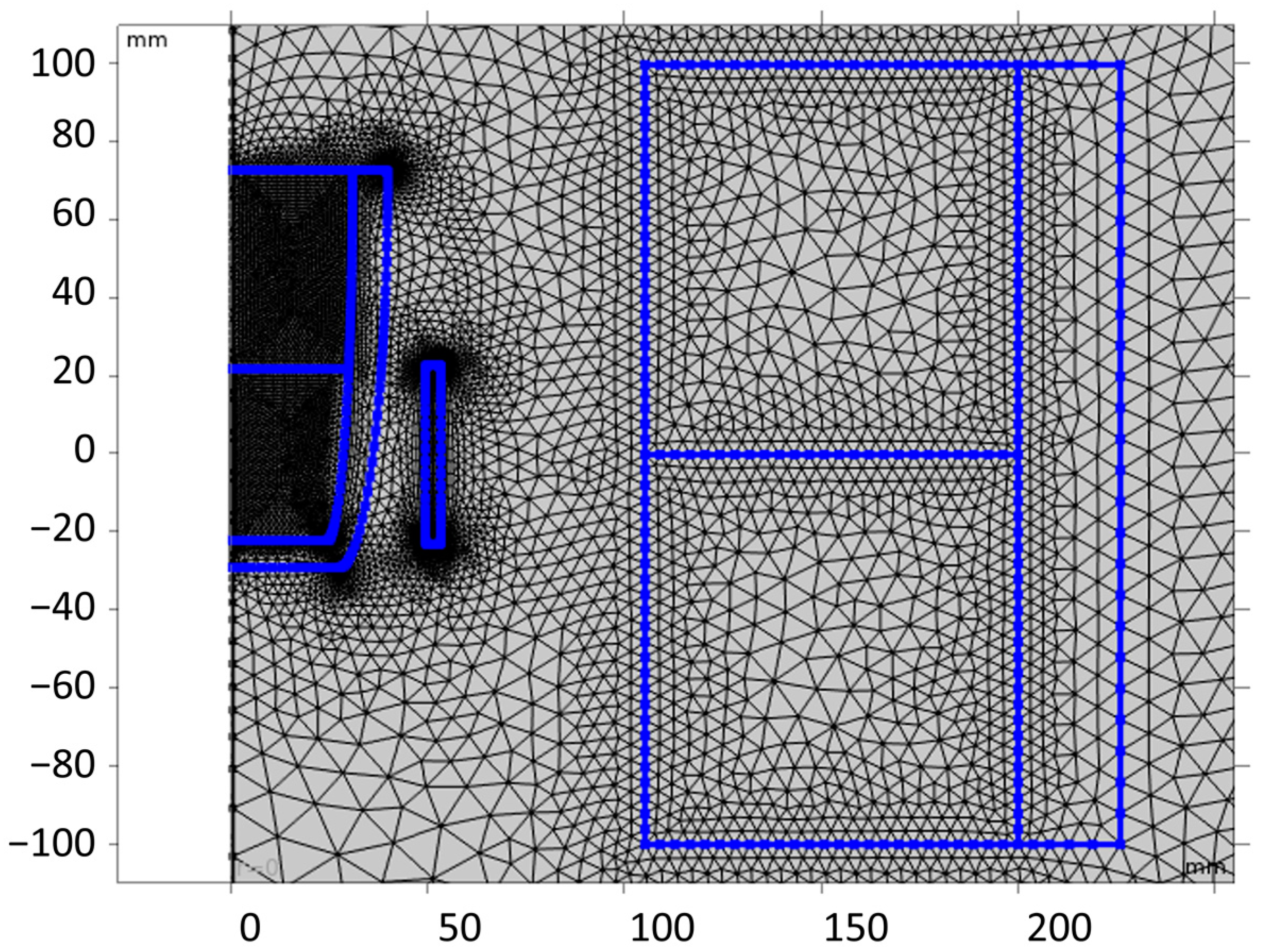
A simple 2D-axisymmetric model has been developed to simulate the EM pulse-generated surface deformation and pressure inside the crucible. For this purpose, the COMSOL Multiphysics 6.0 software, which uses the finite element method, has been chosen. The model consists of air, magnet, iron yoke, inductor coil, and liquid metal domains, as shown in Figure 3. The mesh consists of ~20 k elements, most of which are triangles, but some quadrilateral elements are also used at the boundaries near the inductor coil. The free time stepping method has been chosen for the transient study.
The main equations describing the problem include the incompressible Navier–Stokes equation (Equation (8)), Ampere’s law in combination with Ohm’s law (Equation (9)), Cahn–Hillard equation, and substitutive relations (Equations (10) and (11)):
u t + u u = - p ρ - g z + ν 2 u + J × B ρ + F S T , · u = 0 ,
where u is velocity; t is time; and p , ρ , g , z , ν , J , B and F S T are pressure, density, acceleration due to gravity, vertical coordinate, kinematic viscosity, induced current density, magnetic field, and surface tension force, respectively,
× 1 μ × A = J + × M , J = - σ A t + φ - u × × A , B = × A ,
where μ , A , M , σ , and φ are relative magnetic permeability, magnetic vector potential, magnetization, electrical conductivity, and electrical potential, respectively,
ϕ t + u ϕ = γ λ ε 2 ψ , ψ = - ε 2 ϕ + ϕ 2 - 1 ϕ ,
σ = 2 2 3 λ ε , γ = χ ε 2 , F S T = λ ε 2 ψ ϕ ,
where ϕ , γ , λ , ε , σ and χ are the dimensionless phase field variable, mobility, mixing energy density of the system, measure of the interface thickness, surface tension coefficient, and mobility tuning parameter, respectively. In the model, the surface tension coefficient for the Al6061 melt is set to 0.737 N/m [24]. The crucible walls have no-slip condition for velocity, and they have a wetting angle of 90 degrees specified for the liquid aluminum alloy and air contact at the wall. The properties of the fluid domain inside the crucible are defined using a continuous step function. Gravity helps the perturbed metal to return to its initial state. The permanent magnets have a remanence of 1.38 T, and the magnetic properties of the iron yoke are defined using the magnetization curve relation given for the cast iron material from the built-in material library. The phase field method allows for interface tracking during the free surface deformation induced by the AC coil inductor. The experimentally generated inductor current for the PMF has been approximated using a damped sine function, as shown in Figure 2B.

5. Results

5.1. Numerical Results

The developed model allows evaluation of the induced force and pressure, as well as ability to obtain the melt surface deformations caused by EM interaction. Figure 4 shows the magnetic field, EM force (A), and pressure (B) in the liquid 6061 aluminum alloy skin layer and center. For simplicity and easy comparison, the inductor current, magnetic field, and EM force (Figure 4A) or pressure (Figure 4B) have all been displayed on the same vertical axis. The magnetic field strength pattern in the skin layer matches that of the EM pulse in the coil. In contrast, the magnetic field in the crucible center shows a 180° phase shift compared to that in the skin layer. Initially, the radial component of the EM force has a negative value in the skin layer meaning that the liquid is being compressed inwards creating a low-pressure region at the crucible wall and a high-pressure region in the center. It then oscillates around zero until the excitation from the inductor coil fades away. The radial component of the EM force in the center is always zero due to the axial symmetry.
The force and pressure distributions have been captured at 6 pulse stages and are displayed in Figure 5 and Figure 6. From stages 1 to 3, the Lorentz force is directed radially inward, and from stages 4 to 6 it is pointing outward. The force amplitude and direction both highly depend on the radial position due to the magnetic field penetration depth inside the metal. The radial component of the EM force dominates the axial component, and it is the main cause for the bulging deformation of the liquid metal free surface.
For effective particle agglomerate dispersion purposes, it is important to obtain pressure oscillations throughout the whole melt volume. Figure 6 shows that the pressure values easily cover the range from −100 kPa to 150 kPa during the EM pulse discharge. These values are much greater than the cavitation threshold of pure aluminum, which is experimentally measured at 65 kPa [15]. The results suggest that particle agglomerates, which form during the particle admixing, can be broken apart using the present technique.
The numerical model can be validated by comparing the numerical results with the experimental results and analytical estimates. The free surface bulging deformation during a single EM pulse shows good qualitative and quantitative agreement with the experiment and analytics. The EM force generated pressure reaches ~100 kPa in the liquid aluminum alloy for the 26 kA case and ~194 kPa for the 40 kA current case, which is a slight overestimation of the theoretical model which yields 190 kPa. That can be attributed to the numerical implementation and choice of the exact location of the pressure measurement in the model. Figure 7 shows the liquid aluminum 6061 alloy surface deformation during the interaction of the PMF and BDC magnetic field. Video from the experiment can be seen in supplementary materials. The surface deformation evolution can be characterized by four separate stages: flat surface, flat bump, maximum gaussian bump, and small bump. Fluid surface motion lasts for around 150 ms until it returns to the initial flat state. This repeats with every EM pulse. Melt under the EM impact was filmed with a high-speed camera up to 960 fps from various angles. The depiction of the experiment is an illustration of what authors directly observed during the experiments and from the captured videos.

5.2. Influence on Microstructure

For the microstructure experiment, authors used Sn-10%wt.Pb alloy. This alloy is widely used to study various influences on the solidification microstructure [4,5,17]. It is well known that forced convection leads to grain refinement and avoids segregation. Liquid Sn-10%wt.Pb metal was filled in the crucible and overheated 100 degrees above the melting temperature; then it was put in the magnetic system and was left there to solidify under EM pulses. It took roughly 10 min for the alloy to solidify, and electromagnetic interaction was maintained during this time. Samples were cut from the longitudinal plane in the middle of the crucible. They were etched with glycerol, nitric acid, and hydrochloric acid mixture. The microstructures are compared in Figure 8. The average grain size is determined using the intercept method (ASTM E112). The grains are much finer with the pulsed magnetic field interaction. The average grain size of the reference sample (Figure 8A) and the sample solidified under BDC magnetic field (Figure 8B) is 220 µm, whereas with BDC and pulsed magnetic field combination the grain size is reduced to 140 μm (Figure 8C,D). Grain size differs significantly between the solidified sample without a pulsed magnetic field and with PMF. Results show that their microstructure barely changes in experiments with 1 and 3 pulses per second. This is a well-known phenomena; if forced convection is present, then grain size is reduced significantly compared to a regime without convection, but further increase in convection velocity has little impact on grain size [25]. Close to the alloy surface, the structure is much more fragmented because a lot of oxides and porosity are mixed into the metal. It can be avoided by adding inert gas under the lid instead of air. In the case of a faster cooling rate, pulse frequency might influence the microstructure.
During the electromagnetic treatment, significant surface deformation of the melt was observed, which led to increased oxidation of the metal and pores close to surface. In the middle, a fine-grained microstructure with lots of fine-structured regions is obtained compared to the sample without the pulsed EM interaction, as shown in Figure 9. The microstructure of the reference sample that solidified without the magnetic field (Figure 9A) shows that the tin-rich phase (dark) and lead-rich phase (light) are both separated by sharp borders. In contrast, if BDC and pulsed magnetic fields are both applied, the tin-rich and lead-rich phase regions become much smaller, and the intergrain space is filled with the eutectic mixture of Sn-Pb as shown in Figure 9B.

5.3. Influence on Particle Distribution

For the particle distribution experiment, Al6061 alloy with TiB2 was used. Samples were produced by using the compo-casting method with mechanical stirring [26]. During the experiment, 425 g of Al6061 alloy and 34 g of TiB2 nanopowder (98+% purity and 2–12 µm size) were used. The 2 components were mixed together with a stainless-steel propeller attached to an electric handheld drill while the alloy was in a semisolid state. In this case, a large proportion of nanopowder at 8 wt% was used. Using a high-speed propeller and mushy aluminum consistency, the powder was successfully admixed. The previously prepared alloy was overheated above the melting temperature and then left under the electromagnetic treatment until the melt solidified. After that, the mixture was heated to 750 °C. In this liquid state, the crucible was transferred to the electromagnetic processing setup. The melt solidified in around 5 min. The alloy solidified under electromagnetic interaction. Pulsed field peak intensity was 0.5 T. It was observed that some of the particles rose to the surface during solidification; however, most of them stayed deeper in the melt volume.
Figure 10 shows optical microscopy images taken from the center region of the samples. These investigations clearly show that there is a significant reduction of particle agglomerates over the whole volume of the sample. Without EM, treatment particle agglomerates were all over the sample surface. The size of the agglomerates was up to 1 mm in diameter, as shown in Figure 10A. After the combined PMF and BDC magnetic field treatment, such large agglomerates were not obtained. While some particle agglomerates were still present after the EM treatment, they were much smaller, with the characteristic size below 100 µm, as shown in Figure 10B.
The observed improvement in the particle distribution could mainly be caused by two factors. First, during the EM treatment the liquid melt is stirred for up to 5 min. Because the flow is very rapid and intense, the agglomerates could have been dispersed by the melt flow. Second, the achieved pressure oscillations are high enough to reach cavitation, which is one of the mechanisms that can disperse particle agglomerates. In this case, it was not possible to detect the cavitation effect. Nevertheless, presence of both factors could have resulted in improved particle distribution.

6. Conclusions

In this article, authors demonstrate an experimental setup where pulsed and static magnetic fields are applied to metallic alloys during solidification. Electromagnetically induced pressure pulses reach an amplitude of 190 kPa in liquid metal, which is sufficient to initiate cavitation. It is experimentally demonstrated that such pulsed and DC field interaction helps to refine grain structure for Sn-10%wt.Pb alloy and improve TiB2 particle distribution in 6061 aluminum alloy. A pulsed magnetic field alone creates strong liquid metal free surface deformation and even splashing. If BDC magnetic field is applied, melt splashing is suppressed, and pressure inside the core of the liquid is two times larger. Numerical modelling of the fluid flow and electromagnetic process is used to support the experiment and give the explanation of the physical phenomena taking place during the EM interaction.

Supplementary Materials

The following supporting information can be downloaded at: https://www.mdpi.com/article/10.3390/cryst13020259/s1.

Author Contributions

Conceptualization, A.B.; methodology, I.K. (Imants Kaldre); software, I.K. (Ivars Krastiņš); validation, I.K. (Ivars Krastiņš) and I.Ka.; investigation, M.M., M.K., and I.K. (Imants Kaldre); resources, T.B.; writing—original draft preparation, M.M.; writing—review and editing, I.K. (Imants Kaldre) and I.K. (Ivars Krastiņš); visualization, M.M. and M.K.; supervision, I.K. (Imants Kaldre); project administration, T.B.; funding acquisition, T.B. All authors have read and agreed to the published version of the manuscript.

Funding

This research is supported by ERDF project “Electromagnetic technology with nano-particle reinforced light alloy crystallization process for 3D additive manufacturing applications” (No. 1.1.1.1/19/A/080). Imants Kaldre’s work is supported by postdoctoral research grant « Electromagnetic methods for metal matric nano-composite production » No. 1.1.1.2/VIAA/2/18/264. Mikus Milgrāvis’s work is supported by project “Strengthening of the capacity of doctoral studies at the University of Latvia within the framework of the new doctoral model”, identification No. 8.2.2.0/20/I/006.

Data Availability Statement

Not applicable.

Conflicts of Interest

The authors declare no conflict of interest.

References

  1. Sulaiman, S.; Zulkifli, Z.A. Effect of mould vibration on the mechanical properties of aluminium alloy castings. Adv. Mater. Process. Technol. 2018, 4, 335–343. [Google Scholar] [CrossRef]
  2. Yu, Y.D.; Li, C.X. The effect of alternative low frequency electromagnetic field on the solidification microstructure and mechanical properties of ZK60 alloys. Mater. Des. 2013, 44, 17–22. [Google Scholar] [CrossRef]
  3. Wang, Y.; Zhao, S.; Guo, Y. Numerical Simulation and Experimental Investigation of the Preparation of Aluminium Alloy 2A50 Semi-Solid Billet by Electromagnetic Stirring. Materials 2020, 13, 5470. [Google Scholar] [CrossRef]
  4. Willers, B.; Eckert, S.; Michel, U.; Haase, I.; Zouhar, G. The columnar-to-equiaxed transition in Pb–Sn alloys affected by electromagnetically driven convection. Mater. Sci. Eng. A 2005, 402, 55–65. [Google Scholar] [CrossRef]
  5. Campanella, T.; Charbon, C.; Rappaz, M. Grain refinement induced by electromagnetic stirring: A dendrite fragmentation criterion. Metall. Mater. Trans. A 2004, 35, 3201–3210. [Google Scholar] [CrossRef]
  6. Zhao, Z.; Liu, Y.; Liu, L. Grain Refinement Induced by a Pulsed Magnetic Field and Synchronous Solidification. Mater. Manuf. Process. 2011, 26, 1202–1206. [Google Scholar] [CrossRef]
  7. Ma, X.; Li, Y.; Yang, Y. Grain refinement effect of a pulsed magnetic field on as-cast superalloy K417. J. Mater. Res. 2009, 24, 2670–2676. [Google Scholar] [CrossRef]
  8. Ma, X.; Li, Y.; Yang, Y. The origin of nuclei and the refinement mechanism for solidified superalloy IN718 under pulsed magnetic field. J. Mater. Res. 2009, 24, 3689–3692. [Google Scholar] [CrossRef]
  9. Bao, X.; Ma, Y.; Xing, S.; Liu, Y.; Shi, W. Effects of Pulsed Magnetic Field Melt Treatment on Grain Refinement of Al-Si-Mg-Cu-Ni Alloy Direct-Chill Casting Billet. Metals 2022, 12, 1080. [Google Scholar] [CrossRef]
  10. Zhang, L.; Zhan, W.; Jin, F.; Zhou, Q. Microstructure and properties of A357 aluminium alloy treated by pulsed magnetic field. Mater. Sci. Technol. 2018, 34, 698–702. [Google Scholar] [CrossRef]
  11. Zhang, J.; Jie, J.; Lu, Y.; Zhang, Y.; Zou, C.; Fu, Y.; Li, T. Fabrication of carbon fibers reinforced Al-matrix composites in pulsed magnetic field. J. Mater. Res. Technol. 2021, 11, 197–210. [Google Scholar] [CrossRef]
  12. Padhi, P.; Kar, S.K. A Novel Route for Development of Bulk Al/SiC Metal Matrix Nanocomposites. J. Nanotechnol. 2011, 2011, 1–5. [Google Scholar] [CrossRef]
  13. Li, X.; Yang, Y.; Weiss, D. Theoretical and experimental study on ultrasonic dispersion of nanoparticles for strengthening cast Aluminum Alloy A356. Metall. Sci. Tecnol. 2008, 26, 12–20. [Google Scholar]
  14. Kaldre, I.; Bojarevičs, A.; Grants, I.; Beinerts, T.; Kalvāns, M.; Milgrāvis, M.; Gerbeth, G. Nanoparticle dispersion in liquid metals by electromagnetically induced acoustic cavitation. Acta Mater. 2016, 118, 253–259. [Google Scholar] [CrossRef]
  15. Vivès, C. Crystallization of aluminium alloys in the presence of cavitation phenomena induced by a vibrating electromagnetic pressure. J. Cryst. Growth 1996, 158, 118–127. [Google Scholar] [CrossRef]
  16. Abramov, O.V. Action of high intensity ultrasound on solidifying metal. Ultrasonics 1987, 25, 73–82. [Google Scholar] [CrossRef]
  17. Hua, J.; Zhang, Y.; Wu, C. Grain refinement of Sn–Pb alloy under a novel combined pulsed magnetic field during solidification. J. Mater. Process. Technol. 2011, 211, 463–466. [Google Scholar] [CrossRef]
  18. Jie, J.C.; Yue, S.P.; Liu, J.; StJohn, D.H.; Zhang, Y.B.; Guo, E.Y.; Wang, T.M.; Li, T. Revealing the mechanisms for the nucleation and formation of equiaxed grains in commercial purity aluminum by fluid-solid coupling induced by a pulsed magnetic field. Acta Mater. 2021, 208, 116747. [Google Scholar] [CrossRef]
  19. Chen, Q.P.; Oguma, H.; Shen, H.F. Numerical Simulation of Electromagnetic Phenomena and Solidification under a Pulsed Magnetic Field. Mater. Sci. Forum 2019, 944, 52–58. [Google Scholar] [CrossRef]
  20. Morgan Advanced Materials. SALAMANDER Crucibles. 2013. Available online: https://www.morganmms.com/media/1751/salamander-super-mgam.pdf (accessed on 17 January 2023).
  21. Halbach, K. Specialty magnets. AIP Conf. Proc. 1987, 153, 1277–1295. [Google Scholar] [CrossRef]
  22. Milgrāvis, M.; Bojarevičs, A.; Gaile, A.; Geža, V. Design of a System to Compose 50 Hz Alternating and Static Magnetic Field From Induction Coil and Permanent Magnets. IEEE Magn. Lett. 2020, 11, 1–4. [Google Scholar] [CrossRef]
  23. Grants, I.; Bojarevičs, A.; Gerbeth, G. Analytical solution for the diffusion of a capacitor discharge generated magnetic field pulse in a conductor. AIP Adv. 2016, 6, 65014. [Google Scholar] [CrossRef]
  24. Bainbridge, I.F.; Taylor, J.A. The surface tension of pure aluminum and aluminum alloys. Metall. Mater. Trans. A 2013, 44, 3901–3909. [Google Scholar] [CrossRef]
  25. Kurz, W.; Fisher, D.J. Fundamentals of Solidification, 4th ed.; Trans Tech Puplications Ltd.: Stafa-Zurich, Switzerland, 1998. [Google Scholar]
  26. Panwar, N.; Chauhan, A. Fabrication methods of particulate reinforced aluminium metal matrix composite—A review. Mater. Today Proc. 2018, 5, 5933–5939. [Google Scholar] [CrossRef]
Figure 1. Principal scheme (axial symmetry) of the experimental setup. The setup dimensions are shown in mm. 1-steel magnetic field concentrators. 2-permanent magnet assembly, white arrows show magnet magnetization. 3-copper inductor. 4-liquid aluminum alloy. 5-graphite crucible.
Crystals 13 00259 g001
Figure 2. (A) Electrical scheme of the pulsed magnetic field source. (B) Measured pulse current in the coil.
Crystals 13 00259 g002
Figure 3. Meshed geometry of the liquid metal crucible and induction coil inside the permanent magnet system.
Crystals 13 00259 g003
Figure 4. Graphs show electrical current in induction coil and resulting magnetic field. (A) EM force in liquid metal skin layer and center. (B) pressure in liquid metal skin layer and center.
Crystals 13 00259 g004
Figure 5. Lorentz force distribution during the first period of the EM pulse: 1—initial, 2—ramp-up, 3—top peak, 4—ramp-down, 5—zero cross, and 6—bottom peak.
Crystals 13 00259 g005
Figure 6. Pressure distribution during the first period of the EM pulse: 1—initial, 2—ramp-up, 3—top peak, 4—ramp-down, 5—zero cross, and 6—bottom peak.
Crystals 13 00259 g006
Figure 7. Free surface deformation caused by 26 kA current pulse at different times captured by camera. Numerical results are compared to experiment captures and depictions of the experiment.
Crystals 13 00259 g007
Figure 8. Microstructure of the Sn-10%wt.Pb alloy: (A) Reference sample; (B) Solidified under DC magnetic field BDC = 0.4 T; (C) Solidified under BDC = 0.4 T and pulses 1 Hz; (D) Solidified under BDC = 0.4 T and pulses 3 Hz.
Crystals 13 00259 g008
Figure 9. Comparison of microstructure of solidified Sn-10%wt.Pb alloy: (A) solidified alloy without magnetic field; (B) Solidified alloy under DC (B = 0.4 T) and pulsed (B = 0.5 T) magnetic field combination.
Crystals 13 00259 g009
Figure 10. Optical microscope images. White arrows show particles into the alloy. (A) without electromagnetic processing, particles are in agglomerates; (B) with pulsed electromagnetic field processing.
Crystals 13 00259 g010
Table 1. Physical properties of materials at melting temperature (liquid).
PropertyAluminium 6061Sn-10%wt.Pb
Electric conductivity (MS/m)3.62.0
Density (kg/m3)23007000
Melting temperature (°C)640190
Viscosity (mPa∙s)23
Skin depth (Equation (3)) (mm)911
Disclaimer/Publisher’s Note: The statements, opinions and data contained in all publications are solely those of the individual author(s) and contributor(s) and not of MDPI and/or the editor(s). MDPI and/or the editor(s) disclaim responsibility for any injury to people or property resulting from any ideas, methods, instructions or products referred to in the content.

