Article

Highly Nonlinear Composite-Photonic Crystal Fibers with Simplified Manufacturing Process and Efficient Mid-IR Applications

1
Nano-Photonic and Optoelectronic Research Laboratory (NORLab), Shahid Rajaee Teacher Training University, Tehran 16788-15811, Iran
2
Faculty of Electrical Engineering, Shahid Rajaee Teacher Training University, Tehran 16788-15811, Iran
*
Author to whom correspondence should be addressed.
Crystals 2023, 13(2), 226; https://doi.org/10.3390/cryst13020226
Submission received: 3 January 2023 / Revised: 21 January 2023 / Accepted: 23 January 2023 / Published: 26 January 2023

Abstract

:
This paper reveals special design features of the proposed highly nonlinear circular-lattice-silicon-core and silica-doped-with-fluorine (1%) cladding-composite photonic crystal fiber (PCF) in the Mid-infrared region of the spectrum. A region of small negative group velocity dispersion (GVD), managed higher order dispersions (HODs), and unique nonlinearity of silicon have been used to demonstrate a supercontinuum broadening from 1500 nm to 4700 nm with consumption of low input power of 400 W over short fiber distances. It will be also shown that the fiber’s high-level engineered structure finally results in a simple manufacturing process compared with other designed nano-sized silicon PCFs. The designed fiber could have massive potential in gas sensing, soliton effect pulse compression, spectroscopy, material processing, etc.

1. Introduction

Photonic crystal fibers (PCFs) with different structures have received a great deal of consideration in recent years because of their far-reaching applications in the optical community, such as optical amplifiers, optical sensors, nonlinear optics, fiber optical communication, and other areas [1,2,3]. An extensive diversity of soft-glass and non-glass fibers have been weighed along the expansion of near- and middle-infrared wideband supercontinuum (NIR/Mid-IR WBSC) optical sources [2,3,4,5,6]. Supercontinuum generation (SCG) that uses non-conventional fibers, such as AS2S3 & AS2Se3 glasses, Bi2O3, tellurite, MgF2, and silicon, is still an ongoing topic among the optical scientists. Nowadays, silicon (Si) is one of the well-known applicable Mid-IR materials for manufacturing complicated optical devices [3,4]. Higher nonlinear refractive index of silicon material, which is about 100 times that of conventional silica (SiO2), could result in achieving valuable optical properties and, finally, in Mid-IR ultra-wideband (UWB) supercontinuum generation with lower consumption of energies [3]. By using silicon as the background material of PCFs, dispersion management becomes a major challenge as it allows deviations in the wavelengths selection of the supercontinuum (SC) pump. Another challenge in such cases is the fabrication processes of silicon PCFs [3,5,6,7].
Recently, silicon PCFs have been manufactured by a new method, called “magnesium thermic method”, with a unique ability to maintain the dimensions of the corresponding fibers. Furthermore, several fabrication methods for the plain and composite photonic crystal fibers have also been reported [3,7,8,9,10,11]. The review of the mentioned reports revealed a high cost of the design and fabrication of sub-micron PCFs because of their complicated manufacturing process. On the other hand, in spite of existing challenges relevant to the PCFs manufacturing process, their nonlinear applications, such as ultra-narrow femtosecond optical pulses generation, broadband spectrum generation, optical filters, etc. [3], have attracted many scientists because of the value PCFs bring to telecommunications, the medical industry, the military, etc. [3,12,13,14,15,16,17]. Multiple research associations have presented and proposed novel strategies, designs, and procedures to show the ultra-broadband (UBB) Mid-IR supercontinuum by using different kinds of PCFs so far [2,3,4,5,6,17,18,19,20,21,22,23]. For instance, recently, Ghanbari et al. numerically proposed a nano-sized silicon PCF exhibiting a broadband SCG in the wavelength range of 1400 nm to 5400 nm when pumped by a 100-fs laser input pulse at 2500 nm [3]. Ahmadian et al. introduced a novel structure of chalcogenide core-tellurite cladding composite PCF with a large birefringence property, efficient for SC generation in the Mid-IR region of the spectrum [1]. More recently, Ahmad et al. generated a broad supercontinuum of 8000 nm by using 10 kW input pump power in a novel chalcogenide PCF structure [5]. In 2019, Chauhan et al. numerically simulated ultra-wideband supercontinuum generation of 12,500 nm at the wavelength of 3100 nm in a novel designed PCF as a complementary example [6]. In 2017, a supercontinuum spectrum of 580 nm in the visible regime was generated by Ghanbari et al. using a MgF2 PCF [2]. In 2000, a 550 THz supercontinuum, extending from the violet to the infrared, was generated experimentally by propagating pulses of 100 fs through a conventional PCF [13]. Soon afterward, a 3.8 W continuum was generated from 1065 nm to 1375 nm by pumping in a honeycomb fiber by Avdokhin et al. [14]. Van et al. experimentally investigated supercontinuum generation of 550 nm in a carbon tetrachloride hollow-core photonic crystal fiber at 15,560 nm by using an input pulse of 90 fs [15]. The results were in good agreement with the numerical simulations. As a complimentary example, Gao et al. generated, both mathematically and experimentally, a 2650 nm supercontinuum by using a highly nonlinear fiber at the central wavelength of 1400 nm [16]. However, according to our investigation of all the above-mentioned instances, the missing point is giving special attention to simplifying the manufacturing process.
This paper describes in detail the origins of the PCF modeling for ultra-wideband supercontinua generation in the Mid-IR regime along with focusing on simplifying the manufacturing process. Our study also presents a new PCF design based on a quad-ring structure of air holes along the fiber. We propose generating ultra-wideband spectra in a negative GVD region of our proposed C-PCF by using the silicon material as the core of the fiber and silica doped with fluorine (1%) in the cladding, and by simultaneously optimizing the zero dispersion wavelengths (ZDWs) and fiber structural parameters. Our study will show that appropriately designed parameters of the proposed fiber result in significantly decreasing the complexities of the manufacturing process compared with other highly nonlinear PCFs with the same structure and different background materials.

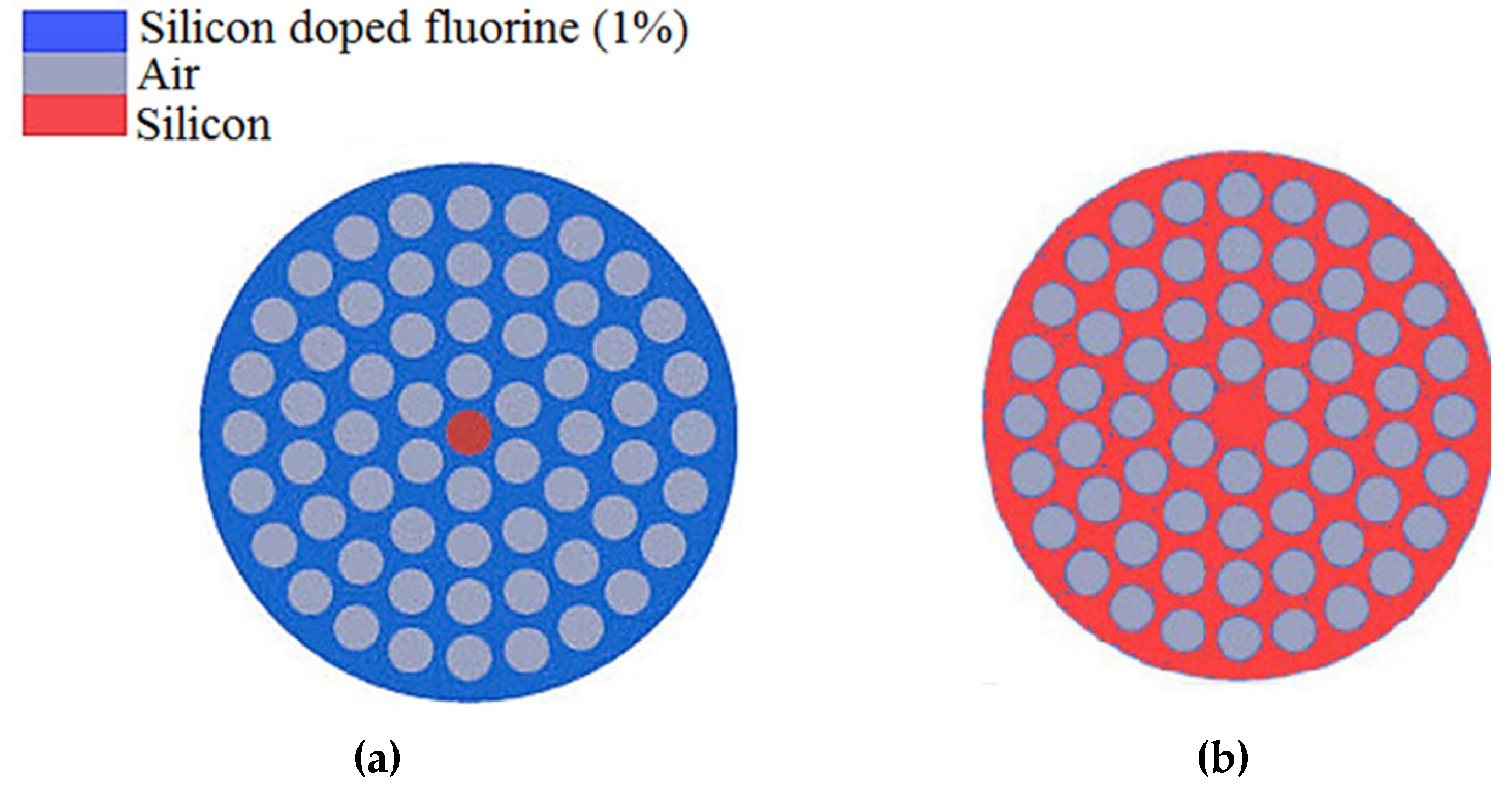
2. The PCF Structure Analysis

The designed composite PCF (C-PCF) has a silicon core and silica doped with fluorine (1%) cladding with embedded four rings of air holes in a circular lattice. We used the below form of the Sellmeier equation [3,4] to find the relevant amounts of the refractive indexes of the selected materials in the core and cladding of the fibers such as silicon and fluorine (1%) doped silica [24]:
n sellmeier λ = 1 + n = 1 N A n λ 2 λ 2 a n 2
where A n and a n n = 1.2.3 N are the fitting variables which are relevant to the kind of the applied materials. The operational wavelength ranges are shown by the term of λ . The term of n( λ ) on the left-hand side of the above equation is the refractive indexes of the selected materials as a function of different wavelengths [3,21,24]. The relevant coefficients for silicon material are A 1 = 9.7 , A 2 = 0.936 , a 1 = 0.08 × 10 6 , a 2 = 0.134 × 10 6 [3,4] and also similar to the silicon, for silica doped with fluorine (1%), the relevant coefficients are, A 1 = 0.691116 , A 2 = 0.399166 , A 3 = 0.890423 and a 1 = 0.068227 , a 2 = 0.116460 , a 3 = 9.993707 [24]. Therefore, we can calculate the wavelength–dependent refractive indexes of silicon and silica doped with fluorine (1%) by using:
n si , co λ = 1 + 9.7 λ 2 λ 2 0.08 × 10 6 2 + 0.936 λ 2 λ 2 0.134 × 10 6 2
n doped silica , co λ = 1 + 0.691116 λ 2 λ 2 0.068227 2 + 0.399166 λ 2 λ 2 0.116460 2 + 0.890423 λ 2 λ 2 9.993707 2
The designed parameters of PCFs are relevant to the terms of d,   Λ , and d c which represent the hole diameter, hole pitch, and core diameter, respectively. The first proposed silica-doped-with-fluorine (1%) cladding PCF is a silicon core and silica-doped-fluorine (1%) cladding PCF, and the other one is an entirely background silicon PCF (S-PCF) with the same structure of core and lattice of air holes. The schematics of both the entirely silicon and composite PCFs (S & C-PCFs) are shown in Figure 1. The Mid-IR sensing behavior of both proposed C-PCF photonic crystal fibers can be characterized by sensitivity, effective area, and birefringence. These properties can be investigated by using Ref. [20]. For this purpose, the power fraction of the light in the proposed hybrid photonic crystal fiber can be given by:
P = E X H Y E Y H X d x   dy C O R E E X H Y E Y H X d x   dy T O T A L
where Ex, Ey, Hx, Hy refer to the electric and magnetic fields in x- and y-directions, respectively. The interaction of the light can be then used to estimate the relative sensitivity (Sr) as in Ref. [20], and it is introduced as the ratio of the product of refractive index of the core to the real part of the effective mode index of the proposed fiber. It is noteworthy that, in this study, the main focus is on the OCT application of the designed PCF; however, we have provided the relevant explanation in the text to show the other capabilities of the presented PCFs.

3. Results and Discussions

In order to generate supercontinuum, it is necessary to derive optical characteristics of the fibers that are directly involved in the wave equation. First, we calculated the propagation constant of the HE11 guided mode ( β ) by using the finite-difference time-domain (FDTD) method [3,25,26]; then, we extracted the relevant values of the effective refractive indexes ( n eff ); finally, we investigated the most important optical characteristics, such as effective area ( A eff ), nonlinear coefficient, total loss, and higher-order dispersions. In our theoretical analysis, we considered total internal reflection (TIR) as the case of mode confinement in the cores of both proposed PCFs. In the following, all of the above-mentioned parameters were optimized for efficient generation of ultra-broadband supercontinuum in the Mid-IR regime because of its valuable applications in several aspects, such as telecommunications [3,25], OCT applications [2], optical sensing [1,26,27,28], etc.

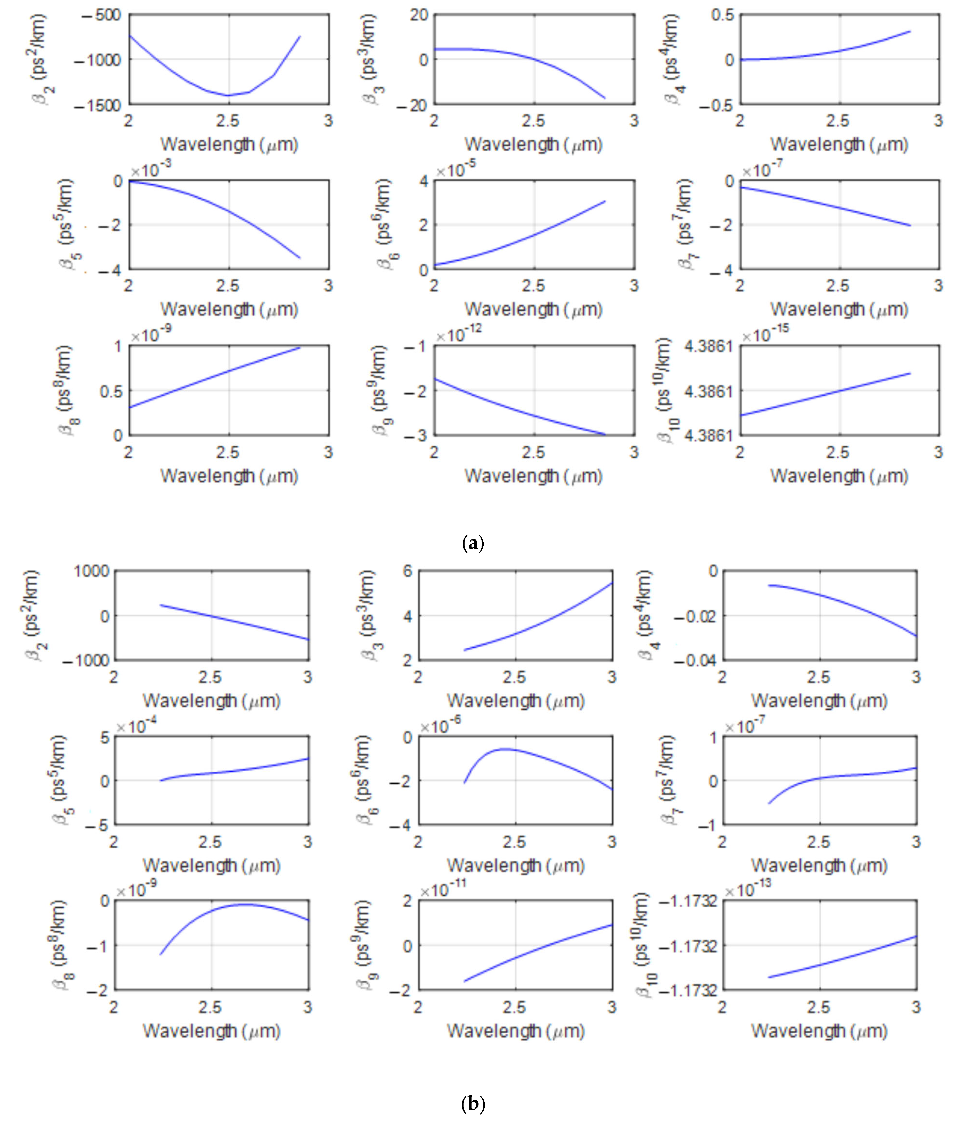
3.1. Dispersion Analyzing

The dispersion plays an important role in optical pulses propagation along the fiber as it causes the pulse broadening and, consequently, changes the phase velocity of the optical pulse’s components. On the other hand, fiber’s dispersions generally determine the phase-matching conditions. It determines the proficiency of nonlinear processes in photonic crystal fibers [26,27]. Total dispersion,   D t λ , including the material and waveguide dispersions, can be described by [3,6]:
D t λ = λ 2 Re n eff c λ 2
where λ is the operational wavelength and c , is the light velocity. The waveguide, material, and total dispersions of the fiber are shown by the terms of D w , D m , and D t , respectively. As stated, n s is the refractive index of the selected material in the core of the fiber and can be directly calculated by using the Sellmeier formula, and Re   n eff is the real part of calculated effective refractive index. In our computations, both the material dispersions of the silicon and silica doped with fluorine (1%) have been taken into the calculations simultaneously. During our calculations, we had to gratify the material dispersion of both designed fibers by using the waveguide dispersion. This is because of the large material dispersion values of the silicon in the short-wave-infrared (SWIR) to middle-infrared (Mid-IR) regions of spectra.
The waveguide dispersion of the PCFs can be directly adjusted by changing the structural parameters such as pitch ( Λ ) and normalized hole diameter to pitch ( d Λ ). In addition, me need to consider that during the propagation of the ultra-narrow femtosecond optical pulses, the second GVD and higher-order dispersions, will be of high magnitude and must be included in the account [2,3,29]. The HODs of the PCFs can be derived easily by using the following formula [3,29]:
β n = β n 1 ω                 n = 2 , 3 , 4
where the interdependence of the selected material in the core of the PCF has been also taken into the account. By applying the operational wavelength of 2500 nm through the laser source of Cr + 2 : ZnSe [3,4] as the input pumping wavelength, the extracted dispersion coefficient curves and values are presented in Figure 2 and also listed in Table 1 for both the silicon core and silica-doped-with-fluorine (1%) cladding-composite PCF and the entirely silicon proposed PCF for Λ = 2.5   μ m ,   d Λ = 0.8 and Λ = 0.75   μ m , d Λ = 0.8 , respectively.
In the case of the designed S-PCF, we clearly see a large minimum negative GVD, which is centered at 2500 nm by choosing the nano-sized parameters of Λ = 0.75   μ m and d = 600 nm. A larger minimum negative GVD finally leads to achieving longer dispersion length. It can also minimize the effects of higher-order dispersions on the propagated pulses. It is also very important in supercontinuum generation process because wider supercontinua can be generated in smaller distances of the fiber when the dispersions factors take place in longer lengths of the fiber with minimum limiter effects. In contrast, our proposed C-PCF has lower negative GVD, which is appropriate for the cases with composite materials and one zero dispersion wavelength, which finally causes lower higher-order dispersions. However, the designed C-PCF has smaller dispersion lengths than the designed S-PCF, which means that supercontinua can appear in the longer distances with higher effects of dispersions on the propagated pulses. In addition, in the case of the designed S- PCF, we can see two zero dispersion wavelengths, one at 1800 nm and another one at 3100 nm, from NIR to Mid-IR region of the spectrum, which is a great point to generate ultra-stable supercontinua.
On the other hand, the designed C-PCF has only one ZDW centered at the wavelength of 2490 nm, which shows that the proposed C-PCF is specially designed for Mid-IR applications. The selected ZDW in the designed C-PCF has a low difference with the operational wavelength (2500 nm), which results in obtaining lower and more appropriate second- and higher-order dispersions for Mid-IR nonlinear applications. In spite of all the above-mentioned features in both designed PCFs, paying attention to the manufacturing process is of great importance and is known as a determinative factor. It is clear that in the case of silicon fiber, nano-sized parameters have been used, and it shows much better optical properties compared with the composite designed fiber. This is due to the small differences between the refractive indexes of the core and cladding of the entirely silicon PCFs. In these situations, we have to use sub-micron hole pitches ( Λ ) to cover the wavelength of 2500 nm. In contrast, because of the higher differences between the refractive indexes of the core and cladding of the mentioned composite PCF, we have to use larger hole pitch sizes ( 1   μ m ) to meet the wavelength of 2500 nm. The larger the pitch size is, the easier the manufacturing process is. It means that lower accuracy and, finally, lower costs are needed for manufacturing such efficient composite PCFs in comparison with the silicon nano-sized PCFs.

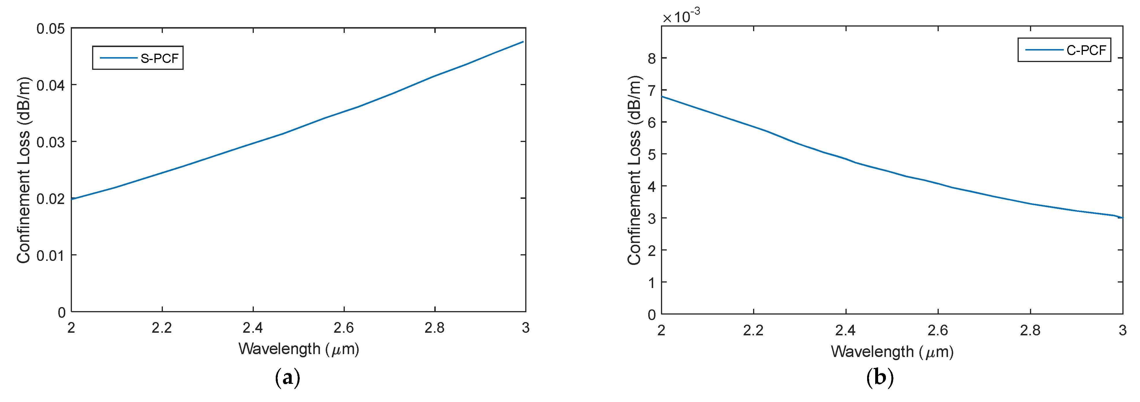
3.2. Confinement Loss

The loss of the photonic crystal fibers may have several reasons, such as material absorptions, macro- or microbending losses, structural imperfection, and finally confinement loss [29,30]. The last one, confinement loss (CL), is due to the mode’s leakage and, also, the heterogeneous and incomplete structure of the PCFs. Depending on the number of the hole rings in the cladding, wavelength, and hole size, the modes will be guided with a loss which is dependent on the structure of the fiber [29,30,31]. The confinement loss can be calculated by [5]:
C L = 40 π   Im n e f f λ ln 10  
where λ is the operational wavelength. The imaginary part of the effective index of guided mode is shown by the term of Im n e f f . C L is presented by the structure of the PCF, especially the size and number of the air holes which are embedded in the cladding structure of the fibers [5,29]. As previously confirmed by several references [1,2,3,4,29], by enhancing the number of air hole rings, the C L decreases significantly. In our study, we used only 4 optimized rings of air holes in the cladding structure to further decrease the confinement loss. Based on our calculations, the selected number of rings is optimized, and implementation of further rings has no influence on the values of confinement loss. The total loss of the fibers can be derived by using the following equation [4,30,31,32],
L t = L m + L c  
where L c is the confinement loss and L m is material loss strongly dependent on the kind of materials which are used in the core of the fiber and estimated to be 3   dB m at 2500 nm for a silicon material [3,4]. Figure 3 depicts the confinement loss for both PCFs as a function of wavelength. As we can see, the designed composite PCF presents a negligible confinement loss of 4.5 × 10 3   dB m , which comes from the fact that the light is completely confined in the core of the composite fiber. In contrast, we have a large amount of 32 × 10 3   dB m for confinement loss of silicon nano-sized PCF, which is approximately seven times that of the composite PCF. We realize that because of the sub-micron dimensions of the designed silicon PCF, the core of the fiber becomes narrower, so the complete confinement of the propagated light becomes limited in the core, and it leaks more in the cladding of the fiber with wavelength increasing. Obtaining lower confinement loss is an important key in manufacturing process of the fibers. Therefore, our proposed composite PCF shows a unique feature in this case.

3.3. Nonlinear Index and Effective Area

In the processes of nonlinear optics, one of the most important key factors in the proficiency of the nonlinear waveguide is nonlinear coefficient [4,31,32]. The nonlinear coefficient of the optical fibers can be calculated as [32]:
γ = 2 π n 2 λ A eff
where n 2 is nonlinear index of the fiber,   λ is the operational wavelength, and A eff , is the fiber core effective area which can be directly calculated by [3,4,32]:
A eff = I d A 2 I 2 d A
where the term of I is the optical intensity. It is evident that the nonlinear coefficient of the fiber,   γ , has a reverse relation with the effective area ( γ 1 A eff ). Therefore, the smaller the effective area is, the larger the nonlinear coefficient is. The effective area and nonlinear coefficients of both designed fibers with the parameters of Λ = 0.75   μ m , d Λ = 0.8 and Λ = 2.5   μ m , d Λ = 0.8 are shown in Figure 4.
As shown in Figure 4, in both PCFs, A eff increases when the nonlinear coefficient decreases as a function of wavelength. It is clear that highly nonlinear coefficients of γ   ω . m 1 = 31 and γ   ω . m 1 = 8.1 can be achieved in our proposed silicon and composite PCFs, respectively. These values are due to the calculated effective areas of 0.55   μ m 2 and 2.83   μ m 2 for the designed S-PCF and C-PCF, respectively. The values of the nonlinear coefficients are more than 27 to 100 times larger than a highly nonlinear silica-based regular photonic crystal fiber and, in one case, 1.5 orders of magnitude lower than that of a chalcogenide-based highly nonlinear photonic crystal fiber (HNL-PCF) [6]. The combined effect of rigid state confinement in a silicon core and an intense nonlinear index of 6 × 10 18   1 ω . m result in highly nonlinear coefficients in our designed PCFs. The designed fibers with such a massive nonlinearity, adjustable dispersions, and low attenuation can have many functional applications, such as sensing, wavelength conversion, material processing, etc.

4. Supercontinuum Generation (SCG)

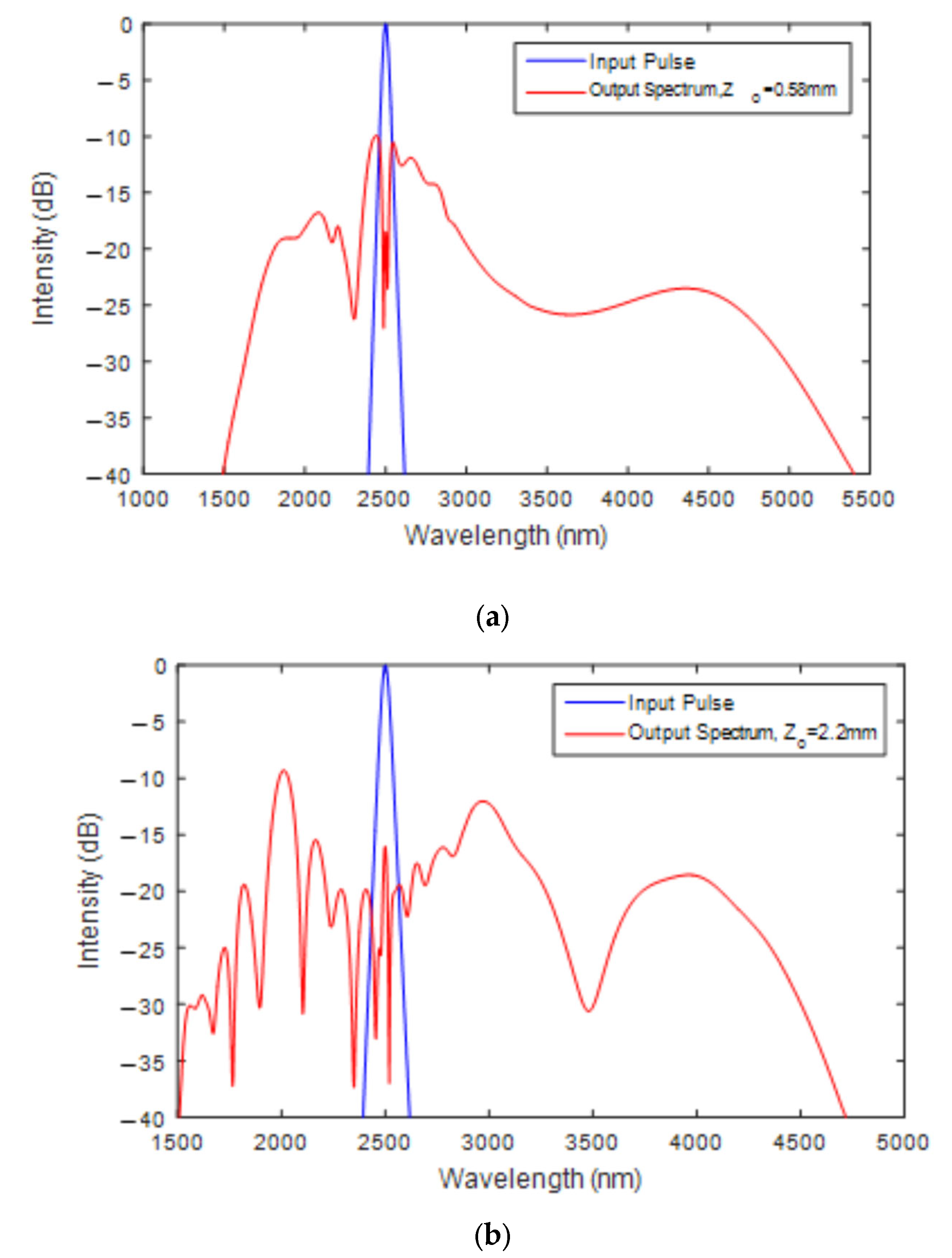
4.1. Spectral Evolution

We employed nonlinear Schrodinger equation (NLSE) as a widely used formula in order to simulate the supercontinuum generation along the proposed PCFs [3,4,33]:
z U z , t = α t 2 U z , t β 2 2 ! 2 t 2 U z , t + β 3 3 ! 3 t 3 U z , t + + i γ ( 1 + i ω 0 t ) [ U z , t R ( t ) U ( z , t t 2 t ] α 4 p a 2 A eff 3 U z , t 6 α TPA 2 γ A eff U z , t 2 3 p a ω U z , t 4 δ 2 1 + i μ N c U z , t
where U z , t shows the envelope of the propagated optical pulse. γ states the nonlinear coefficient of the fiber and 1 ω 0 is responsible for the self- steepening. α t = α m + α cl + α FCA , is the total loss of the fiber, where α m and α cl are the material and the confinement losses and α FCA depicts the free carrier absorption of the silicon material and is calculated to be 66.8 m 1 [4]. The terms of 2   pa and 3   pa are two- and three-photon absorptions. It is noteworthy that in the silicon core PCFs, an additional term of loss with the name of two-photon absorption (TPA) shows itself in a way that it must be included in the wave equation. However, the mentioned destructive loss is zero for the wavelength of higher than 2300 nm [3,34]. The value of 3   pa is estimated to be 0.025 cm 3 GW 2 . α 4 pa is the term of four-photon absorption and similar to the term of three-photon absorption, assumed to be 0.025 cm 3 GW 2 [4]. The factor of N C , is the maximum carrier density and μ and δ are the relevant constants with magnitude of free-carrier absorption (FCA) with the values of 8 × 10 21   1 m 3 , 3.16 and 8.2 × 10 21   1 m 2 , respectively [4]. In this paper, although the needed length of the fiber is in the order of millimeter and the effects of the losses are negligible, we included them into the account to achieve accurate results. In our calculations, we also assumed the following input secant hyperbolic pulse of:
U z = 0. t = P 0 sech t T 0
where T 0 is the width of the input pulse and is relevant to the term of full width at half maximum ( T FWHM ) through:
T FWHM = 1.76 T 0
As previously described, β m shows the higher-order dispersions and can be derived by using Equation (6). R t and h R t depict nonlinear response function and Raman function, respectively, and can be described as:
R t = f R h R t + 1 f R δ t
h R t = τ 1 2 + τ 2 2 τ 1 τ 2 2 exp t τ 2 sin t τ 1
where f R is the Raman constant and it is related to contribution of the Raman respond and is changed by varying the kind of the core materials. τ 1   & τ 2 , are the Raman period and life time. The values of the mentioned parameters can be found in references [3] and [4], respectively.
In this paper, to theoretically simulate the supercontinuum spectra through the designed PCFs, we applied the widely used second-order split-step Fourier method (S-SSFM) [34,35,36,37,38,39,40]. We also used T FWHM = 1.76   fs and a low pulse input power of 400 W for both above-designed PCFs simultaneously. For pumping at wavelength of 2500 nm, we can use Cr + 2 : ZnSe laser sources operating at 2 2.5   μ m [3,5]. Simulation results demonstrated that by using T FWHM = 1.76   T 0 = 100   fs and low input pulse power of 400 W, the ultra-spectral broadening of 3700 nm and 3200 nm generated in the proposed S-PCF and C-PCF, respectively. They can be clearly seen in Figure 5.
The above-generated ultra-broadband spectrum of 3700 nm and 3200 nm by using the low power of 400 W is one of the positive points of this study. However, there are several technical topics in this regard to discuss.
Firstly, we can clearly see that the spectral broadening starting point of the proposed S-PCF is much shorter than the C-PCF. It is because the calculated dispersion length of the designed S-PCF is longer than the dispersion length of C-PCF ( L D SPCF   ( T 0 2 β 2 SPCF ) L D CPCF   ( T 0 2 β 2 CPCF ) ). This is due to the larger derived second-order dispersion in the designed S-PCF than the designed C-PCF. In these situations, the nonlinear effects in the designed S-PCF play a significant role and become dominant more than the designed C-PCF ( L NL CPCF   L NL SPCF ). As a consequence, the evolution of broadening starts sooner in the designed S-PCF ( z opt = 0.58   mm ) than in C-PCF ( z opt = 2.2   mm ).
Secondly, based on our previous explanations, we can see predictable differences, such as spectrum broadening values and also presence of spectral fluctuations in the output spectrum of the designed C-PCF compared with the S-PCF. The mentioned differences are due to the optimized calculations of the second- and higher-order dispersions in the proposed S-PCF and because the contribution of higher-order dispersions to the second-order dispersion in the designed S-PCF is lower than C-PCF. The influence of higher-order dispersions is more negligible compared with the C-PCF. However, it should be noted that although the optical characteristics of the designed S-PCF are ideal for nonlinear applications, our proposed C-PCF’s optical properties are also suitable and acceptable. This can be seen in the values of the pulse broadening in the proposed C-PCF compared with the other scientific outputs.
Thirdly, in this research, the main key factor in choosing the desired fiber for using in the nonlinear applications is the simplicity of its manufacturing process. The designed C-PCF has a bigger size than that of the proposed S-PCF (approximately 3.5 times that of S-PCF). Therefore, it is evident that our proposed C-PCF is much more ideal to use in the Mid-IR nonlinear applications because it includes both unique optical characteristics and a simplified manufacturing process simultaneously. It is due to the fact that the condensation of silica material with fluorine (1%) decreases the cladding refractive index of the proposed C-PCF and finally increases the V parameters of the fiber, which results in bigger required parameters for the design of such fibers.

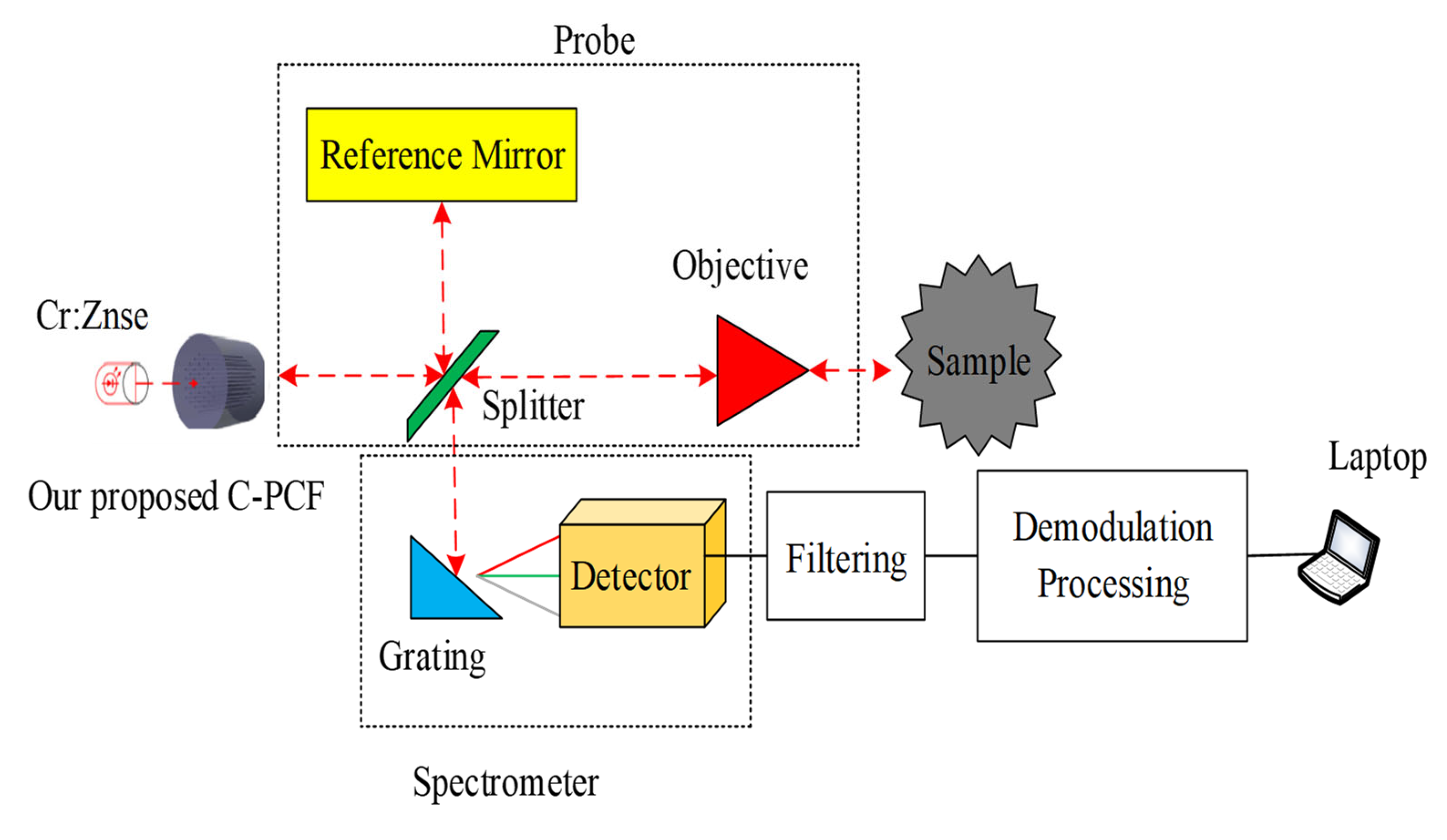
4.2. An OCT Imaging Mid-IR Setup

By using optical coherence tomography (OCT) techniques, we can investigate objects in volumes with very high accuracy and resolution [2,33]. OCT uses the scattering characteristics of the light in a scattered medium. This technique is extensively used in the medical industry (especially medical imaging) and industrial nondestructive testing. Mid-IR OCT allows for higher permeation depths and increased quality compared with conventional NIR-OCT [33,34]. This is due to lower scattering loss at lower frequencies. In this section, we proposed a Mid-IR OCT imaging setup shown in Figure 6. As we can see from the figure, we dedicated our proposed PCF to the input part of the set up. This PCF is connected to the probe and optical source. It acts as a supercontinuum generator. The implemented part is an added section, which can be used in the OCT setups for achieving qualified images because it generates broaden spectra by using very low energies (we described the relevant reasons in the previous sections). This is the fact that distinguishes our proposed setup from the other published works [41,42,43]. The setup’s function can be described as follows: At first, the selected chromium doped Zinc Selenide ( Cr + 2 : ZnSe ) optical laser source generates and emits high-intensity optical pulses with femtosecond durations in the middle-infrared region of spectrum. The generated laser light then is propagated into our proposed silicon-core and silica-doped-with-fluorine (1%) cladding photonic crystal fiber which is attached to an imaging probe. It is notable that the main parts of the mentioned imaging probe (OCT imaging probe) include a splitter of beam, a reflecting prism, a system of mirrors and finally a discoverer. In this proposed setup, the observation of the relevant targets (samples and tissues) become easier by using two additional parts, including a camera and a LED ring for defining the OCT scanning area. In the following, the generated broadband spectrum from the mentioned optical source is divided into two beams, which are called pattern (sample) beam and reference beam. The beam splitter emits the spectrum to the reference mirror (reflecting prism) and to the sample through the mirrors and objective, respectively. Both beams then are mingled in the probe and emit to the photo tracer (detector). Photodetectors are used to convert the optical beams to the analog signals, and its parasite signals then can be removed by any kind of high and band pass relevant filters. For further reduction of the required sampling rate without removing the data of the signals, a demodulator can be used. The demodulator output signal shows an analog video. However, for further and deeper data processing purposes, it is urgent to convert the analog signals to the digital signals (data) by using a microcontroller. After an accurate data analysis and data processing, the received video from the main sample (such as a tissue) can be finally displayed on a screen.

5. Investigation on the Existing Challenges in the Manufacturing Process of the Proposed PCFs

Over the years, several manufacturing techniques such as drilling, capillary stacking, extrusion, and so on, have been applied to design various structures of PCFs. However, during the fabrication process, structural parameters of the PCFs, such as air-hole diameter, pitch, core diameter, and plasmonic metal layer thickness, can be changed [8]. This could either optimize or damage the sensing and other behaviors of the PCFs due to the structural parameters.
Presence of deformed air holes, emergence of additional holes, and perturbations of the structure’s symmetry are the main usual fabrication challenges in the PCFs manufacturing process. Although emergence of additional holes and perturbations of the structure’s symmetry are directly relevant to the selected method of fabrication and the utilized tools during the process, presence of deformed air holes is relevant to the selected parameters at the designing stage. It is also due to very small design of the air holes around the core of the fiber [3]. In this theoretical study, we tried to design a PCF with appropriate structural parameters to prevent air holes deformation under the assumption that the process is ideal. However, we must note that we designed a composite PCF (C-PCF) that cannot be made by using the usual existing techniques. We presented magnesium-thermic method as a novel method for fabricating silicon core PCFs [3]. This method works based on the process of converting silica to silicon by using complicated chemical interactions and specific tankers simultaneously. It must be combined with one of the above-mentioned usual techniques to make the proposed C-PCF. Many unwanted changes can happen, especially in the process of converting, so the deteriorations of the mentioned techniques for hybrid PCFs can be still an ongoing topic.

6. Comparison between the Optical Properties of the Designed PCFs with Other Works

In this section, extensive comparisons between the optical characteristics of our novel designed PCFs and other research findings are presented in Table 2. Comparing the parameters clearly shows that although the designed Silicon PCF displays more ideal optical characteristics, its manufacturing process needs complicated and accurate procedures. The relevant costs increase significantly. On the other hand, our designed C-PCF shows acceptable and competitive optical properties in addition to a much easier manufacturing process because of the optimized implemented structural parameters of the proposed C-PCF.

7. Conclusions

The design of a composite photonic crystal fiber based on silicon-core and silica-doped-with-fluorine (1%) cladding and adjusted dispersion for supercontinuum generation with input pump being located at the wavelength of 2500 nm has been reported. Numerical investigations showed the designed C-PCF as being a suitable PCF for middle-infrared (Mid-IR) supercontinuum generation, especially where only a 5 mm long composite PCF was desired to gain spectral broadening in an optical bandwidth of 3200 nm by using only the input power of 400 W. The major positive and advantageous point of our proposed C-PCF is the simplicity of its manufacturing process compared with other studies. With ultra-wideband SCG, the designed C-PCF has potential to be used in multiple nonlinear applications, especially in Mid-IR OCT. Following our previous assertion, we also proposed a simple imaging OCT-setup to further explain our designed C-PCF functionalities and applications. The proposed setup can be extensively used for ultra-precious imaging with very low consumption of energy.

Author Contributions

A.G.: designed and preformed simulations and analyzed data; S.O.: supervision, edited, and prepared the final draft of the manuscript. All authors have read and agreed to the published version of the manuscript.

Funding

This research received no external funding.

Institutional Review Board Statement

Not applicable.

Informed Consent Statement

Not applicable.

Data Availability Statement

Not applicable.

Acknowledgments

This work was supported by the Nano-photonics and Optoelectronics Research Laboratory (NORLab), Shahid Rajaee Teacher Training University.

Conflicts of Interest

The authors declare no conflict of interest.

Abbreviations

CLConfinement Loss
C-PCFComposite-Photonic Crystal Fiber
FCAFree-Carrier Absorption
FDTDFinite-Difference Time-Domain
fsFemtosecond
GVDGroup Velocity Dispersion
HNLHighly Nonlinear
HODHigher-Order Dispersion
Mid-IRMiddle Infrared
NIRNear Infrared
NLSENonlinear Schrodinger Equation
OCTOptical Coherent Tomography
PCFPhotonic Crystal Fiber
psPicosecond
S-PCFSilicon-Photonic Crystal Fiber
SWIRShort Wavelength Infrared
TPATwo-photon absorption
UBBUltra-Broad Band
UWBUltra-Wide Band
ZDWZero Dispersion Wavelength

References

  1. Ahmadian, A.; Monfared, Y.E. Chalcogenide-tellurite composite photonic crystal fiber. Extreme non-linearity meets large birefringence. Appl. Sci. 2019, 9, 4445. [Google Scholar] [CrossRef] [Green Version]
  2. Ghanbari, A.; Kashaninia, A.; Sadr, A.; Saghaei, H. Supercontinuum generation for optical coherence tomography using magnesium fluoride photonic crystal fiber. Optik 2017, 140, 545–554. [Google Scholar] [CrossRef]
  3. Ghanbari, A.; Kashaninia, A.; Sadr, A.; Saghaei, H. Supercontinuum generation with femtosecond optical pulse compression in silicon photonic crystal fibers at 2500 nm. Opt. Quantum Electron. 2018, 50, 411. [Google Scholar] [CrossRef]
  4. Dashtban, Z.; Salehi, M.R.; Abiri, E. Supercontinuum generation in near- and Mid-infrared spectral region using highly nonlinear silicon-core photonic crystal fiber for sensing applications. Photonics Nanostruct. 2021, 46, 100942. [Google Scholar] [CrossRef]
  5. Ahmad, R.; Komanec, M.; Zvanovec, S. Circular lattice photonic crystal fiber for Mid-IR supercontinuum generation. IEEE Photon. Technol. Lett. 2016, 28, 2736–2739. [Google Scholar] [CrossRef]
  6. Chauhan, P.; Kumar, A.; Kalra, Y. A dispersion engineered silica-based photonic crystal fiber for supercontinuum generation in near-infrared wavelength region. Optik 2019, 187, 230–237. [Google Scholar] [CrossRef]
  7. Medjouri, A.; Abed, D. Theoretical study of coherent supercontinuum generation in chalcogenide glass photonic crystal fiber. Optik 2020, 219, 165178. [Google Scholar] [CrossRef]
  8. Guiyao, Z.; Zhiyun, H.; Shuguang, L.; Lantian, H. Fabrication of glass photonic crystal fibers with a die-cast process. Appl. Opt. 2006, 45, 4433–4436. [Google Scholar] [CrossRef]
  9. Kim, J.; Kim, H.; Paek, U.; Lee, B.; Eom, J. The fabrication of a photonic crystal fiber and measurement of its properties. J. Opt. Soc. Korea 2003, 7, 79–83. [Google Scholar] [CrossRef] [Green Version]
  10. Cho, T.Y.; Kim, G.H.; Lee, K. Study on the fabrication process of polarization maintaining photonic crystal fibers and their optical properties. J. Opt. Soc. Korea 2008, 12, 19–24. [Google Scholar] [CrossRef] [Green Version]
  11. Azman, M.F.; Mahdiraji, G.A.; Wong, W.R.; Aoni, R.A.; Adikan, F.R.M. Design and fabrication of copper-filled photonic crystal fiber-based polarization filters. Appl. Opt. 2019, 58, 2068–2075. [Google Scholar] [CrossRef]
  12. Chauhan, P.; Kumar, A.; Kalra, Y. Numerical exploration of coherent supercontinuum generation in multicomponent GeSe2-As2Se3-PbSe chalcogenide based photonic crystal fiber. Opt. Fiber Technol. 2020, 54, 102100. [Google Scholar] [CrossRef]
  13. Ranka, J.K.; Windeler, R.S.; Stentz, A.J. Visible continuum generation in air–silica microstructure optical fibers with anomalous dispersion at 800 nm. Opt. Lett. 2000, 25, 25–27. [Google Scholar] [CrossRef]
  14. Avdokhin, A.V.; Popov, S.V.; Taylor, J.R. Continuous-wave, high-power, Raman continuum generation in holey fibers. Opt. Lett. 2003, 28, 1353–1355. [Google Scholar] [CrossRef]
  15. Van, T.H.; Rafal, K.; Grzegorz, S.; Khoa, D.X.; Van, C.L.; Marek, T.; Mariusz, K.; Ryszard, B.; Jacek, P. Femtosecond supercontinuum generation around 1560 nm in hollow-core photonic crystal fibers filled with carbon tetrachloride. Appl. Opt. 2020, 59, 3720–3725. [Google Scholar]
  16. Gao, W.; Zhang, L.; Chen, H.; Li, J.; Jiang, Y.; Wan, L.; Zhou, Y.; Ma, X. Experimental study of supercontinuum generation in step-index highly nonlinear fibers. Res. Sq. 2021, 11, 806–810. [Google Scholar]
  17. Saghaei, H.; Van, V. Broadband mid-infrared supercontinuum generation in dispersion-engineered silicon-on-insulator waveguide. J. Opt. Soc. Am. B 2019, 36, A193–A202. [Google Scholar] [CrossRef]
  18. Ghosh, A.N.; Meneghetti, M.; Petersen, C.R.; Bang, O.; Brilland, L.; Venck, S.; Troles, J.; Dudley, J.M.; Sylvestre, T. Chalcogenide-glass polarization-maintaining photonic crystal fiber for mid-infrared supercontinuum generation. J. Phys. Photonics 2019, 1, 044003. [Google Scholar] [CrossRef]
  19. Jamatia, P.; Saini, T.S.; Kumar, A.; Sinha, R.K. Design and analysis of a highly nonlinear composite photonic crystal fiber for supercontinuum generation: Visible to mid-infrared. Appl. Opt. 2016, 55, 6775–6781. [Google Scholar] [CrossRef]
  20. Rajesh, A.; Sivasankar, P.; Sai, S.; Chandini, M. Design of Highly Sensitive Hybrid Honeycomb Photonic Crystal Fiber for Sensing C8H8O3/AsCl3/C8H10 Analyte. Res. Sq. 2022, 21, 1–20. [Google Scholar]
  21. Saini, T.S.; Kumar, A.; Sinha, R.K. Broadband mid-infrared supercontinuum spectra spanning 2–15 μm using As2Se3 chalcogenide glass triangular-core graded-index photonic crystal fiber. J. Light. Technol. 2015, 33, 3914–3920. [Google Scholar] [CrossRef]
  22. Gao, W.; Duan, Z.; Asano, K.; Cheng, T.; Deng, D.; Matsumoto, M.; Misumi, T.; Suzuki, T.; Ohishi, Y. Mid-infrared supercontinuum generation in a four-hole As2S5 chalcogenide microstructured optical fiber. Appl. Phys. B Laser Opt. 2014, 116, 847–853. [Google Scholar] [CrossRef]
  23. Singh, N.; Hudson, D.D.; Yu, Y.; Grillet, C.; Jackson, S.D.; Casas-Bedoya, A.; Read, A.; Atanackovic, P.; Duvall, S.G.; Palomba, S.; et al. Mid-infrared supercontinuum generation from 2 to 6 μm in a silicon nanowire. Optica 2015, 2, 797–802. [Google Scholar] [CrossRef]
  24. Sellmeier, W. To explain the abnormal sequence of colors in the spectrum of some substances. J. Y. Phys. 1871, 143, 272–282. (In German) [Google Scholar]
  25. Cheshberah, A.; Seifouri, M.; Olyaee, S. Design of normal dispersion with Ge11.5As24Se64.5/Ge20Sb15Se65 chalcogenide PCF pumped at 1300 nm for supercontinuum generation. Opt. Quantum Electron. 2021, 53, 461. [Google Scholar] [CrossRef]
  26. Sharma, R.; Kaur, S.; Chauhan, P.; Kumar, A. Computational design & analysis of GeSe2-As2Se3-PbSe based rib waveguide for Mid-infrared supercontinuum generation. Optik 2020, 220, 165032. [Google Scholar]
  27. Ademgil, H.; Haxha, S. Endlessly single mode photonic crystal fiber with improved effective mode area. J. Opt. Commun. 2012, 285, 1514–1518. [Google Scholar] [CrossRef]
  28. Islam, I.; Paul, B.K.; Ahmed, K.; Hasan, R.; Chowdhury, S.; Islam, S.; Sen, S.; Bahar, A.N.; Asaduzzaman, S. Highly birefringent single mode spiral shape photonic crystal fiber-based sensor for gas sensing applications. Sens. Bio-Sens. Res. 2017, 14, 30–38. [Google Scholar] [CrossRef]
  29. Hooper, L.E.; Mosley, P.J.; Muir, A.C.; Wadsworth, W.J.; Knight, J.C. Coherent supercontinuum generation in photonic crystal fiber with all-normal group velocity dispersion. Opt. Express 2011, 19, 4902–4907. [Google Scholar] [CrossRef] [Green Version]
  30. Wang, Y.; Yan, X.; Cheng, T.; Li, S. High sensitivity with wide detection range refractive index sensor based on dual-core photonic crystal fiber. J. Opt. 2022, 51, 397–407. [Google Scholar] [CrossRef]
  31. Seifouri, M.; Alizadeh, M.R. Supercontinuum Generation in a Highly Nonlinear Chalcogenide/MgF2 Hybrid Photonic Crystal Fiber. IJOP 2018, 12, 69–78. [Google Scholar] [CrossRef] [Green Version]
  32. Kumar, P.; Fiaboe, K.F.; Roy, J.S. Highly birefringent do-octagonal photonic crystal fibers with ultra flattened zero dispersion for supercontinuum generation. J. Microw. Optoelectron. Electromagn. Appl. 2019, 18, 80–95. [Google Scholar] [CrossRef]
  33. Sorahi-Nobar, M.; Maleki-Javan, A. Supercontinuum generation for ultrahigh-resolution OCT via selective liquid infiltration approach. Radio Eng. 2018, 27, 16–21. [Google Scholar] [CrossRef]
  34. Ferhat, M.L.; Cherbi, L.; Haddouche, I. Supercontinnum generation in silica photonic crystal fiber at 1.3µm and 1.65µm wavelength for optical coherence tomography. Optik 2018, 152, 106–115. [Google Scholar] [CrossRef]
  35. Kirishna, G.D.; Prasanan, G.; Sudheer, S.K.; Pillai, V.P.M. Analysis of zero dispersion shift and supercontinuum generation near-IR in circular photonic crystal fibers. Optik 2017, 145, 599–607. [Google Scholar] [CrossRef]
  36. Arif, M.F.H.; Biddut, M.J.H. Enhancement of relative sensitivity of photonic crystal fiber with high birefringence and low confinement loss. Optik 2017, 131, 697–704. [Google Scholar] [CrossRef]
  37. Sharma, M.; Konar, S.; Khan, K.R. Supercontinuum generation in highly nonlinear hexagonal photonic crystal fiber at very low power. J. Nanophotonics 2015, 9, 093073. [Google Scholar] [CrossRef]
  38. Bozolan, A.; Gerosa, R.M.; De Matos, C.; Romero, M.A.; Cordeiro, C.M.B. Sealed liquid-core photonic crystal fibers for practical nonlinear optics, nanophotonics, and sensing applications. J. SPIE 2010, 7839, 78390. [Google Scholar]
  39. Raei, R.; Heidari, M.E.; Saghaie, H. Supercontinnum generation in organic liquid-liquid core cladding photonic crystal fiber in visible and near infra-red regions. J. Opt. Soc. Am. B 2018, 36, 323–330. [Google Scholar] [CrossRef]
  40. Ahamad, R. Mid-Infrared Supercontinuum Generation in Photonic Crystal Fibers. Ph.D. Thesis, Czech Technical University, Prague, Czech Republic, 2016. [Google Scholar]
  41. Ghanbari, A.; Sadr, A.; Hesari, H.T. Modeling photonic crystal fiber for efficient soliton-effect compression of femtosecond optical pulses at 850 nm. Arab. J. Sci. Eng. 2014, 39, 3917–3923. [Google Scholar]
  42. Boris, I.G. Modern technologies for retinal scanning and imaging: An introduction for the biomedical engineer. Biomed. Eng. 2014, 13, 52. [Google Scholar]
  43. Aumann, S.; Donner, S.; Fischer, J.; Müller, F. Optical Coherence Tomography (OCT): Principle and Technical Realization. In High Resolution Imaging in Microscopy and Ophthalmology; Bille, J., Ed.; Springer: Berlin/Heidelberg, Germany, 2019; Chapter 3. [Google Scholar] [CrossRef] [Green Version]
  44. Van Le, H.; Hoang, V.T.; Nguyen, H.T.; Long, V.C.; Buczynski, R.; Kasztelanic, R. Supercontinuum generation in photonic crystal fibers infiltrated with tetrachloroethylene. Opt. Quantum Electron. 2021, 53, 187. [Google Scholar]
  45. Kiroriwal, M.; Singal, P. Numerical analysis on the supercontinuum generation through Al0.24Ga0.76As based photonic crystal fiber. Sādhanā 2021, 46, 167–174. [Google Scholar] [CrossRef]
  46. Borgohain, N.; Sharma, M.; Konar, S. Broadband supercontinuum generation in photonic crystal fibers using cosh-Gaussian pulses at 835 nm wavelength. Optik 2016, 127, 1630. [Google Scholar] [CrossRef]
  47. Hadi, H. Modelling Silica Core-Air Clad Nanowires for Supercontinuum Generation. Master’s Thesis, Qazvin Azad University, Qazvin, Iran, 2012; pp. 1–135. [Google Scholar]
Figure 1. The schematics of the proposed PCFs with (a) silicon core and fluorine (1%) doped silica cladding, (b) entirely silicon background.
Crystals 13 00226 g001
Figure 2. Higher-order dispersions of (a) silicon PCF for Λ = 0.75   μ m ,   d Λ = 0.8 and (b) C-PCF for Λ = 2.5   μ m , d Λ = 0.8 .
Crystals 13 00226 g002
Figure 3. Confinement losses of (a) the designed silicon PCF for Λ = 0.75   μ m ,   d Λ = 0.8 and (b) the designed composite PCF for Λ = 2.5   μ m ,   d Λ = 0.8 as a function of wavelengths.
Crystals 13 00226 g003
Figure 4. Effective areas and nonlinear coefficients for (a,b) entirely silicon PCF and (c,d) silicon-core and silica-doped-with-fluorine (1%) cladding PCF with Λ = 0.75   μ m , d Λ = 0.8 and Λ = 2.5   μ m , d Λ = 0.8 , respectively.
Crystals 13 00226 g004
Figure 5. Spectral evolution of broadening in (a) S-PCF and (b) C-PCF.
Crystals 13 00226 g005
Figure 6. The proposed Mid-IR OCT-setup.
Crystals 13 00226 g006
Table 1. The higher order dispersions coefficients of our proposed PCFs.
Λ = 2.5   μ m     ,   d Λ = 0.8 Λ = 0.75   μ m   ,   d Λ = 0.8
β n / Material .     ps n km C-PCFS-PCF
β 2 –12.5–1400
β 3 30
β 4 1 × 10 2 0.072
β 5 1 × 10 4 2 × 10 3
β 6 1 × 10 6 2.5 × 10 5
β 7 0 2 × 10 7
β 8 1 × 10 8 0.7 × 10 9
β 9 6 × 10 10 2.5 × 10 12
β 10 1.1 × 10 13 4.3 × 10 15
λ   nm 25002500
ZDW (nm)24901800 & 3100
Table 2. Comparison between the results and other studies.
Parameters β 2   p s 2 km β 3   p s 3 km β 4   p s 4 km β 5   p s 5 km γ   w . m 1 Spectral BroadeningPower/Energy λ   nm A eff   ( μ m 2 ) L Fiber ( cm / mm ) The PCF Type
The first proposed work−12.53 1 × 10 2 1 × 10 4 8.13200 nm400 W25002.832.2 mmC-PCF
The second proposed work−140000.072 2 × 10 3 313700 nm400 W25000.530.58 mmSilicon-PCF
Ref. [7]150−10.0041 1.9 × 10 5 0.294400 nm3 nJ30001515 mmChalcogenide
PCF
Ref. [6]−2.30.049 4.4 × 10 4 1.69 × 10 6 0.0262270 nm8000 W13004.737 cmSilica-PCF
Ref. [31]−3.70.150.0012 1 × 10 5 14.985000 nm200 W20,0000.6810 cmC-PCF
Ref. [21]−170Not listedNot listedNot listed1.914,000 nm3500 W40004.16 mmAs2Se3-
PCF
Ref. [32]2.253 1.4 × 10 2 4 × 10 5 9.44 × 10 11 3.41500 nm10,000 W125010.515 cmC-PCF
Ref. [41]−320.0011 2 × 10 4 7 × 10 7 0.31200 nm184 pJ8500.8110 mmSilica-PCF
Ref. [5]−0.01070.00145 3.9 × 10 6 2.1 × 10 8 2.36600 nm10,000 W25003.985 mmAs2S3-
PCF
Ref. [44]−4.1Not listedNot listedNot listed0.1891200 nm16,000 W1030 359110 cmC2CL4-
PCF
Ref. [45]−0.0041Not listedNot listedNot listed2.356000 nm2500 W3250Not listed4 mmAl0.24Ga0.76As based PCF
Ref. [46]−11.8 8.1 × 10 2 9.5 × 10 5 2.7 × 10 7 0.11800 nm10,000 W835Not listed0.1 mSilica-PCF
Ref. [47]−10.83Not listedNot listed0.031200 nm20,000 W1550 nm200.3Nanowire
Disclaimer/Publisher’s Note: The statements, opinions and data contained in all publications are solely those of the individual author(s) and contributor(s) and not of MDPI and/or the editor(s). MDPI and/or the editor(s) disclaim responsibility for any injury to people or property resulting from any ideas, methods, instructions or products referred to in the content.

