Article

Ultraviolet Nanosecond Laser-Ablated Groove Analysis of 2.5D Cf/SiC Composites

1
College of Mechanical Engineering, Donghua University, Shanghai 201620, China
2
Shanxi Key Laboratory of Advanced Manufacturing Technology, North University of China, Taiyuan 030051, China
3
Manufacturing Research Center, Georgia Institute of Technology, Atlanta, GA 30332, USA
*
Author to whom correspondence should be addressed.
Crystals 2023, 13(2), 223; https://doi.org/10.3390/cryst13020223
Submission received: 13 November 2022 / Revised: 13 January 2023 / Accepted: 18 January 2023 / Published: 25 January 2023
(This article belongs to the Special Issue Processing Technology of Brittle Crystal Materials)

Abstract

:
The 2.5D Cf/SiC composite is a typical heterogeneous material with the characteristics of anisotropy, which makes it difficult to predict the size and damage removed by the traditional contact removal process. This paper adopted the ultraviolet nanosecond laser to ablate the Cf/SiC composites by considering the heterogeneous structure’s effect. The ablated groove topography and size prediction are effective in revealing the machined quality with predictable groove sizes. The effects of laser processing parameters on the groove morphology and surface thermally affected zone are investigated with the thermal removal mechanism. A regression model is established by considering the scanning times, scanning speed, laser power and pulse width as the main variables. In the regression models, the relative error values are all below 10%. It is revealed that the groove width diminishes with the scanning speed and increases as the laser power increases. However, the influence of the scanning times and pulse width is small, and the overall variation range is within ±10 μm. The results show that the arrangement direction of carbon fibers has an impact on laser processing, especially when the pulse width is 0.25 μs, upon which the opposite change occurs. Carbon fiber grooves are not obvious and are barely observed in the laser processing of the parallel carbon fiber direction, and the grooves are slightly uneven. This study could be helpful in analyzing the grooves of Cf/SiC affected by the laser processing process, which could support the hybrid machining of the Cf/SiC composites.

1. Introduction

Ceramic matrix composites (CMCs) are widely used in high-temperature, wear resistance applications because of their extremely high impact and fatigue resistance performance [1,2,3]. Generally, the Carbon Fiber-reinforced Silicon Carbide ceramics (Cf/SiC) composites are composed of carbon fiber reinforcement, silicon carbide ceramic matrix material and a pyrolytic carbon interface [4]. Compared with traditional structural ceramics or CFRP material, the Cf/SiC composites have demonstrated improved mechanical properties in engineering applications [5,6,7,8], such as a high strength, light mass, high flexural resistance, etc.
However, the heterogeneous structure of carbon fiber and SiC makes traditional machining [9,10,11,12] more difficult in dealing with the fracture cracks, delamination, burrs, etc. Yu et al. [13] showed that 2.5D C/SiC composites have a good fatigue resistance strength of 202.5 MPa, which is equivalent to 78.1% of the ultimate tensile strength. Due to the excellent properties of Cf/SiC composite materials, it is difficult to remove them efficiently and accurately [3,14]. Nowadays, Electric Discharge Machining (EDM), ultrasonic-assisted machining and laser machining are relatively effective methods. Researchers have reported on the EDM of the structure ceramic materials [15]; it has been believed that the microstructure is more suitable for this method [16]. However, functional ceramic materials are polycrystalline materials, which are generally ionic, covalent or both ionic and covalent. The materials are insulative and non-electrical conductive. Therefore, EDM technology has a relatively large limitation in the processing and application of functional ceramic materials. Ultrasonic-assisted machining can process both conductive and insulating materials, and it has a faster processing speed without the generation of heat-affected zones, so it can process engineering structure materials [17]. However, limited by the processing amplitude, the precision of ultrasonic-assisted machining is low. It is only suitable for the surface processing of complex contours, and it is not suitable for processing small holes with a high precision. The abrasive wear during ultrasonic-assisted grinding is twice as high as the material wear, and the cost is higher. Laser machining utilizes the interaction of laser beams with matter to process materials. Laser machining has shown the advantages of a high machining efficiency, a non-contact nature and a lack of tool wear, which make it an effective way to process Cf/SiC composites. The non-contact laser ablation process is very helpful in promoting its engineering applications and machining quality.
Understanding the ablation mechanism and quality evaluation for Cf/SiC composites is very important for its further applications. Zhai et al. [18] explored the effect of fiber orientation on surface morphology. It was found that, depending on different fiber orientations, the surface roughness decreases in different degrees. Lambiase et al. [19] conducted experiments on Cf/SiC composites by changing the laser parameters to explore the effect of the laser parameters on the composites. It is believed that the defects, such as delamination and microcracks, are caused by the heat-affected zone (HAZ). Wei et al. [20] explored a novel method for the underwater femtosecond laser ablation of SiC/SiC composites, which can obtain a high cleanliness and low-oxidation microporous surfaces. Yang and Zhang et al. [21,22] conducted the laser processing of a microstructure for surface creation, which has demonstrated the typical advantages of the contact removal method [23]. Zhai et al. [24] compared the morphologies under different laser processing parameters. It was found that the original surface roughness of C/SiC had a significant effect on the laser ablation morphology. Pan et al. [25] revealed that the surface morphology of the C/SiC composite under laser irradiation is usually divided into a central region, a transition region and a boundary region. Hu et al. [26] studied SiC/SiC through-holes and blind holes processed by a microsecond laser and analyzed their processing characteristics. Liu and Zhang et al. [27] first revealed the ‘ablation evolution behavior’ in the micro-hole machining of 2.5D Cf/SiC composites with a millisecond laser. Zhang et al. [28] studied 2.5D C/SiC composites at room temperature and 900 °C by applying cyclic loads and found that the fracture was closely related to the cracks generated by the crossing of fiber bundles. Deng et al. [29] established a thermal model, which investigates the thermal behavior of single-crystal SiC at different wavelengths and pulse durations and predicts the size and cross-sectional profile of the ablation hole. Liu and Wang et al. [30,31,32] found that when a high-power picosecond laser ablates the C/SiC composites, a large number of gas-phase substances and strong shock waves are generated, and fragments are ejected at a high speed. However, due to the strong thermal effect, the materials are prone to oxidation, stratification and grooving defects [33] in the laser processing process, and the microgrooves are prone to appear in fine processing.
At present, the laser ablation of unidirectional and 2D Cf/SiC composites is widely studied. The 2.5D Cf/SiC composite is different from the unidirectional and 2D Cf/SiC, which mainly uses the weft yarn through the warp to form a braided structure so as to form the interlock. Therefore, 2.5D Cf/SiC has a stronger interlayer bonding strength and better mechanical properties. In the research of laser processing 2.5-dimensional Cf/SiC composites, the surface morphology and its produced groove should be extensively focused on, which is helpful for laser-ablated size and quality prediction. Thus, this paper is devoted to investigating the experimental results of the variation in laser parameters with the groove depth and width prediction model. The research work reflects the changing pattern of the Cf/SiC groove morphology, and the surface thermally affected zone will be further analyzed through systematic experiments.

2. Experiment Setup

2.1. Material Preparation

The 2.5D Cf/SiC composites used in this experiment are provided by Shenyang Liming Engine Co., LTD. (Shenyang, China) and prepared by the chemical vapor infiltration (CVI) method. The preparation method is as follows. First, the T-300 carbon fiber was used as the reinforcing material. The T-300 carbon fiber was prepared into the fiber preform. Second, the carbon fiber precast was placed in a closed reaction chamber with a high temperature; the reaction gases such as H2 and methyltrichlorosilane (MTS) are infiltrated into the interior or surface of the preform to form the ceramic matrix. Table 1 shows the key properties of the 2.5D Cf/SiC. The main components are carbon fiber, SiC ceramics and microplasma silicon. Table 2 shows the physical and mechanical properties of SiC ceramics and carbon fiber. Figure 1 shows the composite weaving structure. The texture morphology and preparation characteristics of carbon fiber can be observed through the surface. The workpiece has a dimensional size of 15 × 15 × 15 mm3.

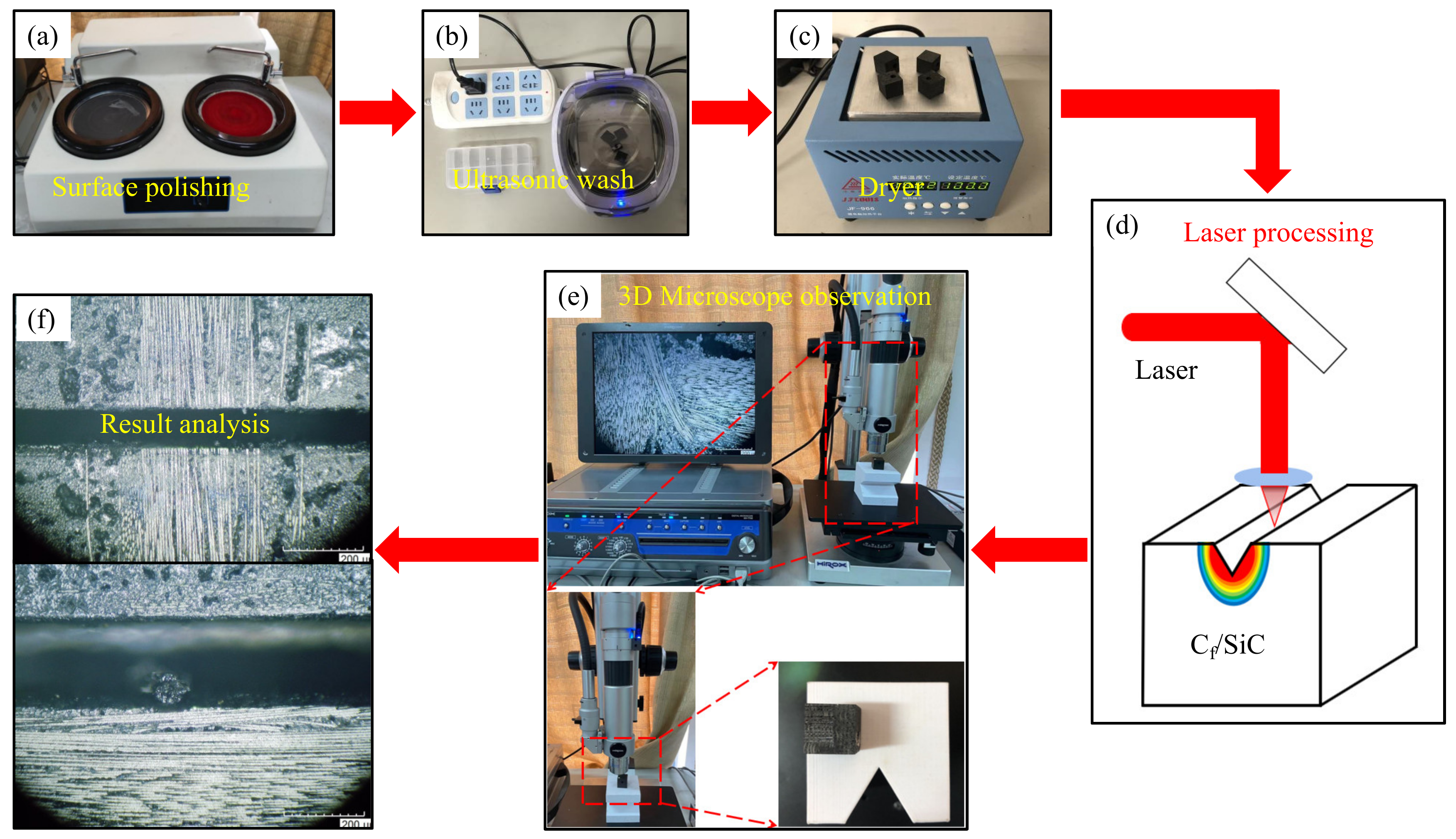
2.2. Experimental Equipment

In the experiments, the Cf/SiC composites are processed by the Huari Poplar nanosecond laser Poplar-355. The temperature of the water cooler is set to be constant at 22 °C before the experiment. The laser z-axis is used to set the defocus distance of the laser processing, and the x-axis and y-axis are used to adjust the experimental platform to determine the laser processing position. The laser beam is emitted from the light outlet to process Cf/SiC composites.
Table 3 shows the parameters of the nanosecond laser. According to the parameter table, the output wavelength of the laser is 355 nm. The output power range is 5–20 W. The pulse width range is 0.15–0.3 μs, and the operating voltage is the standard 220 V with the water-cooling method.

2.3. Overall Experiments Design

Figure 2 is the experimental flow chart of the laser irradiation of Cf/SiC ceramic matrix composites, which is composed of surface grinding and polishing, ultrasonic cleaning, dryer drying, laser irradiation processing, microscope observation and the interpretation of the results. Through changing the scanning times, scanning speed, laser power and pulse width, the observation and analysis of the groove topography and surface thermally affected width of the Cf/SiC composites are thoroughly conducted. The experimental parameters are shown in Table 4. The idea of control variables is adopted, and the other processing parameters remain unchanged in a laser processing experiment with variable parameters. The effects of different processing parameters on the surface groove and surface thermally affected width of the Cf/SiC composites are analyzed, and the causes of these effects are analyzed according to the relevant mechanism.
The surface roughness of composites before processing has a great impact on the processing results. Therefore, the Cf/SiC ceramic matrix composites require pre-experimental treatment before laser irradiation processing. In Wei’s experiments [20], in order to eliminate the effect of surface defects on the material, all samples were polished using standard micron-sized sandpaper and then ultrasonically cleaned in absolute alcohol before processing. In this experiment, the polishing paste of particles of a diameter of 28–1.5 μm is applied to the test mill rotary platform, and Cf/SiC is pressed to the mill rotary platform for surface treatment. Due to the poor removal consistency of Cf/SiC, uneven areas still appear in the surface treatment. With holes in the Cf/SiC composites, the residual grinding fluid may affect the experimental results of the laser processing. Therefore, after the surface treatment, the residual grinding particles and the grinding solution are cleaned with the ultrasonic cleaner and heating dryer. Cf/SiC is soaked in 75% ethanol solution and cleaned for 7 min. The dryer temperature is set at 100 °C for 5 min to ensure that the residual grinding fluid does not remain in the composites, as shown in Figure 2.
A metal plate is placed on the processing platform to avoid direct damage to the processing platform during laser processing. The thickness is 15 mm, and the setting value is 34.5 cm (the initial defocus distance of the laser is 33 cm). The software EzCad2.14.5 is used to set the laser processing parameters and draw the laser processing route. The composite materials are placed in the processing position for laser irradiation processing, as shown in Figure 3.
To ensure the reproducibility of the experiment, each group of experiments is repeated twice. Each observation target datum is the average value obtained from the measured data under that parameter. For example, when the variable parameter is 100 scanning times, three measurement points are taken from the processing lines. The maximum and minimum values are removed to obtain the average value. The surface morphology and data recording of the Cf/SiC composites are observed by a Japanese Haoshi KH-7700 three-dimensional microscope. The main objectives of the observation data after the laser irradiation processing of Cf/SiC composites are the surface groove width, depth and thermally affected zone width, as shown in Figure 4. During the measurement, the data of the main observation target are completely recorded, and the composite material morphology at the point of measurement is saved with a three-dimensional microscope. By observing and recording the groove morphology and the thermally affected zone width, the change law of the Cf/SiC grooves is analyzed.

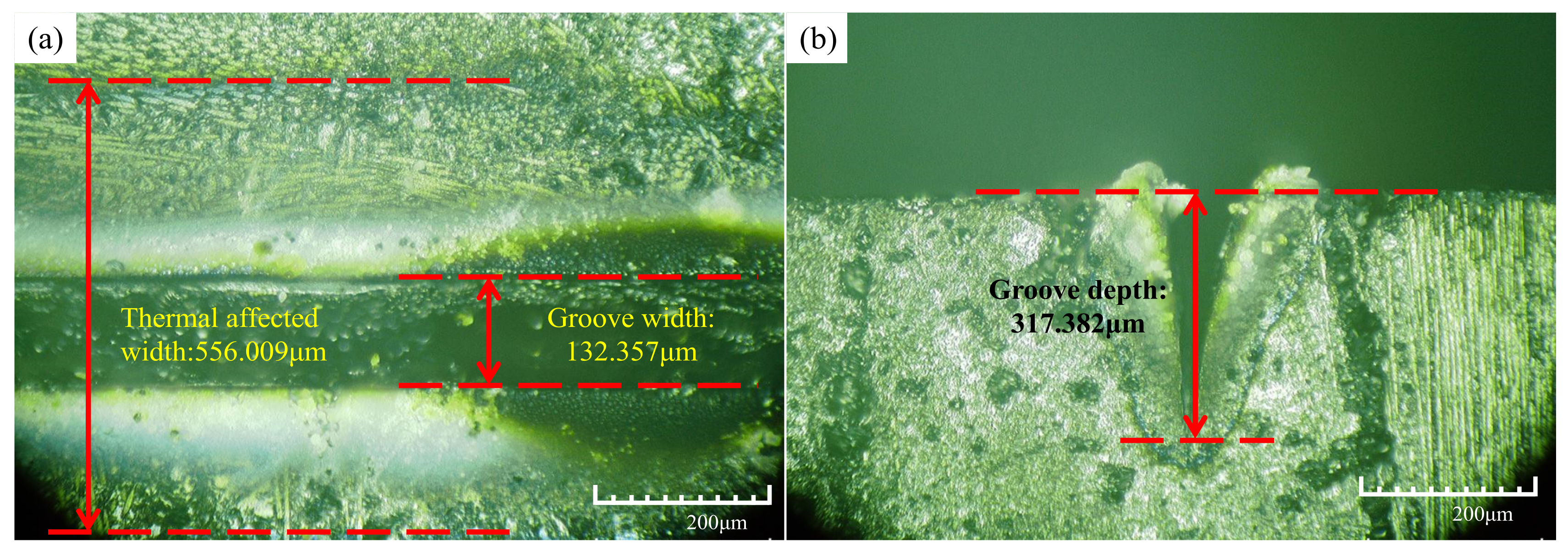
3. Microgroove Analysis

The laser ablation of Cf/SiC composites is controlled by chemical and physical erosion, mainly the physical erosion of the center [37]. The laser energy presents a Gaussian distribution in space, with the largest spot in the center, and the laser energy on both sides of the center of the spot will be smaller and smaller. During the laser irradiation processing of the composites, most of the energy is absorbed by the material, and the surface of the material is ablated, resulting in grooves. The absorbed energy will be conducted and diffused in the Cf/SiC, causing different degrees of thermal damage to the processed material, forming the thermally affected zone.

3.1. Effect of Laser Scanning Times

Figure 5 shows a regular diagram of the effect of laser scanning times on the surface grooves of the Cf/SiC composites (V = 200 mm/s, P = 15 W, Q = 0.3 μs). The experimental results show that with the increment of laser passing numbers, the surface groove width reaches the lowest value when the number is 400, but the overall variation range is small, within ±10 μm. This indicates that scanning times have little effect on the surface groove width of the composites. With the increment of scanning times, the groove depth increases, and the width of the surface thermally affected zone first increases and then decreases. This is because, with the increment of laser scanning times, the energy radiated on the composites increases, increasing the groove depth. However, when the scanning times continue to increase, on the one hand, the laser irradiation energy will ablate and fracture the carbon fibers. On the other hand, the thermal conductivity of carbon fiber is reduced, preventing the spread of the laser heat. Therefore, the surface thermally affected zone tends to decrease.

3.2. Effect of the Laser Scanning Speed

The influence of the laser scanning speed on the surface groove of Cf/SiC composites is shown in Figure 6 (N = 400, P = 15 W, Q = 0.3 μs). The experiments show that with the increment of scanning speed, the surface groove width gradually decreases, and the overall groove depth also decreases. The experimental results of the laser scanning times and laser scanning speed are consistent with the changing trend of the ablative experiments of Jiao and Zhang et al. [38,39], according to the following Equation (1):
E D = P V × φ
where E D is the energy density; P is the laser power; V is the laser scanning speed; φ is a spot diameter [40].
Therefore, with the increment of the laser scanning speed, the laser energy density decreases, and the composites under the same area are irradiated with less laser energy. In addition, the reduction in irradiation time results in the processing area not receiving enough energy to bring the material to the removal temperature. So, the groove width and groove depth decrease. The influence of the laser scanning speed on the width of the thermally affected zone also shows a similar variation law. With the increment of the laser scanning speed, the thermally affected zone width on the surface of the composites first increases and then decreases. When the laser scanning speed increases, the laser has a preheating effect on the composite, and the surface thermally affected zone width increases. With the continuous increment of the scanning speed, the laser energy density decreases, and the laser ablation heat decreases. Therefore, the surface thermally affected zone width becomes smaller.

3.3. Effect of Laser Power

Figure 7 shows the effect of laser power on the surface grooves of Cf/SiC composites (N = 400, V = 200 mm/s, Q = 0.3 μs). The experiments show that, with the increment of power, the surface groove width and groove depth of Cf/SiC gradually increase, according to the following Equation (2):
E = P × Δ τ
where E is the laser pulse energy, P is the pulse power and Δ τ is the pulse time width. It can be seen that, with the increment of laser pulse power, the laser pulse energy increases. The higher the energy, the higher the temperature during irradiation processing. The temperature of the laser center area exceeds the sublimation temperature of the SiC matrix and carbon fiber. As the heat is transferred, the material outside the central area also reaches the melting temperature. Therefore, the groove width and groove depth gradually increase. However, the surface thermally affected zone width gradually decreases. The greater the laser power, the higher the energy efficiency. The lesser the impact of the laser radiation, the less ablation heat is generated.

3.4. Effect of Fiber Direction

By analyzing the experimental results, it is found that the two laser-processing directions of the perpendicular-to-fiber direction and parallel-to-fiber direction show similar laws. The width of the thermally affected zone, in the parallel-to-the-fiber-arrangement direction, is slightly larger than that in the perpendicular-to-the-fiber arrangement direction. However, the groove depth in the parallel direction is smaller than that in the perpendicular direction. This is because the Cf/SiC composites have anisotropy, and the heat generated by laser processing is easy to propagate along the carbon fiber direction. The composite materials at the groove openings are subject to significant machining stress due to the heat and the high-velocity jet of the molten material. When the processing path is parallel to the carbon fiber texture, all parts of the entire fiber will be subjected to processing stress. Due to the good adhesion between the fibers and the matrix, the carbon fibers are not easily broken. When the processing path is perpendicular to the carbon fiber texture, the stress effect on the composite material can only be borne by the local material. Therefore, the carbon fiber will be broken, and the groove width will become larger. According to the theorem of energy conservation, when the heat propagates along the fiber direction, the depth of the crack become smaller. When the heat propagates along the direction of the crack depth, the surface thermally affected zone width become smaller.
In the processing, the laser heat absorbed by the composites will be propagated, along with the carbon fiber. When the temperature rises to a certain level, the high bending resistance of the composite materials will be greatly reduced. As a result, the composite fibers at the openings of the trenches are largely fractured, as shown in Figure 8. As the temperature increases, the thermal diffusivity of Cf/SiC decreases, and the thermal conductivity of the composites also decreases. When the laser scanning times increase, the temperature of the composite processing zone increases, and the thermal conductivity of the Cf/SiC decreases. Therefore, whether it is perpendicular to the fiber direction or parallel to the fiber direction, with the increment of the scanning times, the width of the thermally affected zone decreases. During processing, heat transfer is mainly carried out by diffusion, and the heat transfer speed in the direction of the fiber is significantly faster than that in other directions. Therefore, when the variable parameter is the pulse width, the width of the thermally affected zone perpendicular direction is larger than that of the parallel direction. However, the thermal diffusivity of the 2.5-dimensional braided Cf/SiC composites is mainly affected by the radial direction of the carbon fiber and the SiC matrix [41]. The thermal conductivity of the material is mainly affected by thermal diffusivity. So, in other variable parameter experiments, the width of the thermally affected zone in the parallel direction is slightly larger than that in the perpendicular direction.
As can be seen in Figure 9, the laser irradiation processing is quite different under the processing parameters of the same laser pulse width. The surface groove width shows a trend of decreasing first and then increasing in the perpendicular direction. The overall slight decreases in the parallel direction and the observed data in both processing directions do not fluctuate much, around ±10 μm. However, the changing trends of the surface thermally affected zone width of Cf/SiC composites are opposite in the two laser processing directions. The changing trend of the thermally affected zone width in the perpendicular direction increases first and then decreases. In the parallel direction, the changing trend decreases first and then increases. The changing nodes are all at the parameter of 0.25. This is because the 2.5-dimensional Cf/SiC composites have a strongly anisotropic structure. Therefore, it can be concluded that the fiber arrangement direction has an impact on laser processing, but only when individual parameters change will it have completely opposite effects.

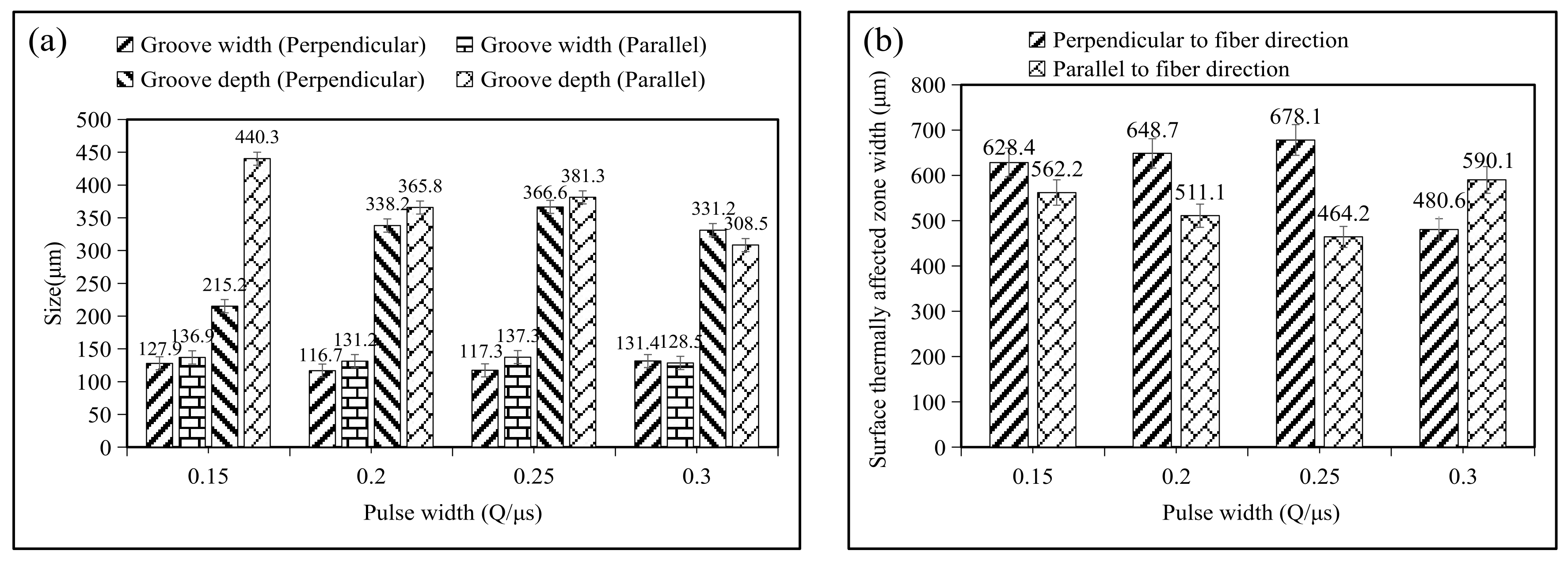
3.5. Effect of Pulse Width

The influence of the pulse width on the surface groove of Cf/SiC composites is shown in Figure 9 (N = 400, V = 200 mm/s, P = 15 W). The experiments show that with the increment of the pulse width, the surface groove width reaches the minimum in the stage of 0.2–0.25 μs, which first decreases and then increases. However, the variation range is small, around ±10 μm. With the increment in the pulse width, the groove depth shows an upward trend in the stage of 0.15–0.25 μs, and the increment is obvious. The range of the thermally affected zone shows an increasing trend in the stage of 0.15–0.25 μs, but the changing trend is not obvious. However, when the laser irradiation direction is parallel to the carbon fiber arrangement direction, the width and depth of the surface grooves in the composites show a decreasing trend as a whole. It is obviously different from the change trend perpendicular to the direction of the fiber arrangement direction. The larger the pulse width of the laser is, the smaller the laser energy density will be. The composite is irradiated with less energy, and the groove width and depth are smaller. The reason for the increment in the groove width is that when the laser pulse width gradually increases, the thermal conductivity of the Cf/SiC composites is increased. With the increment of the pulse width, the width of the perpendicular and parallel fiber arrangement directions shows an opposite trend. This is due to the preheating of the laser processing and the insufficient cooling of the complex, thus increasing the width of the thermally affected zone. Different directions of fibers have different forces on the composite materials: a local fiber is stressed, and the entire carbon fiber is stressed. During processing, heat transfer is mainly carried out by diffusion, but the heat transfer is significantly faster along the fiber direction than in other directions. During laser processing, the laser path will cover the area with more heat transfer when parallel to the carbon fiber texture processing path, resulting in more of a heat overlap in this part. Compared with the perpendicular fiber arrangement direction and the parallel fiber arrangement direction, the groove width trend and the width of the thermally affected zone trend are obviously different, which shows that the fiber arrangement direction affects the grooves.
Pan et al. [25] provided six different power densities, as well as six levels of pulse numbers, when the ablation experiments are conducted for the C/SiC composite. However, they did not perform experimental pretreatment on composites. The laser ablation depth and the number of layers in the experimental results are basically consistent with these experiments, which also explains the reason for the change in the crack depth. Zhang et al. [39] discussed the effects of different processing parameters, including the helical line width and spacing, machining time and scanning speed. The influence trend of factors, such as the laser scanning speed, on the material laser ablation obtained by their experiments is consistent with this paper. However, the groove depth values obtained in the literature were as high as 700 μm and as low as 575 μm, which are much larger than the highest value of 517 μm obtained in this paper, which may be due to the influence of 2.5D composite materials.

4. Discussions

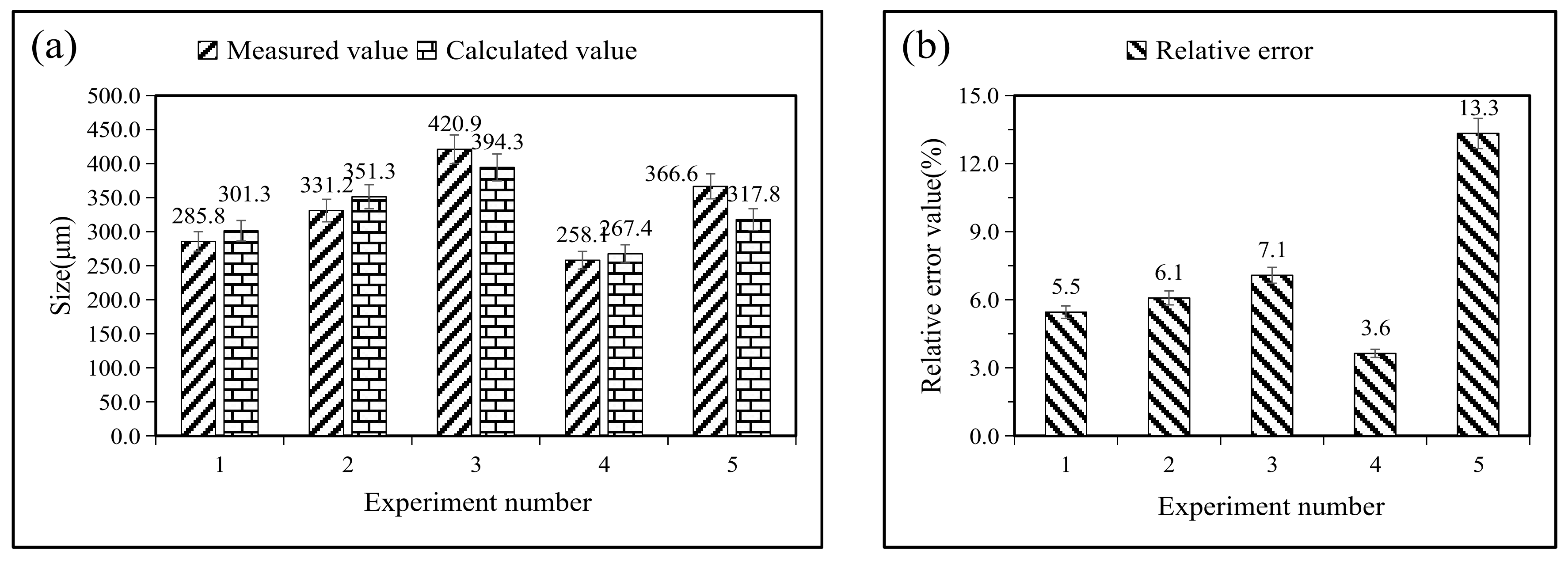
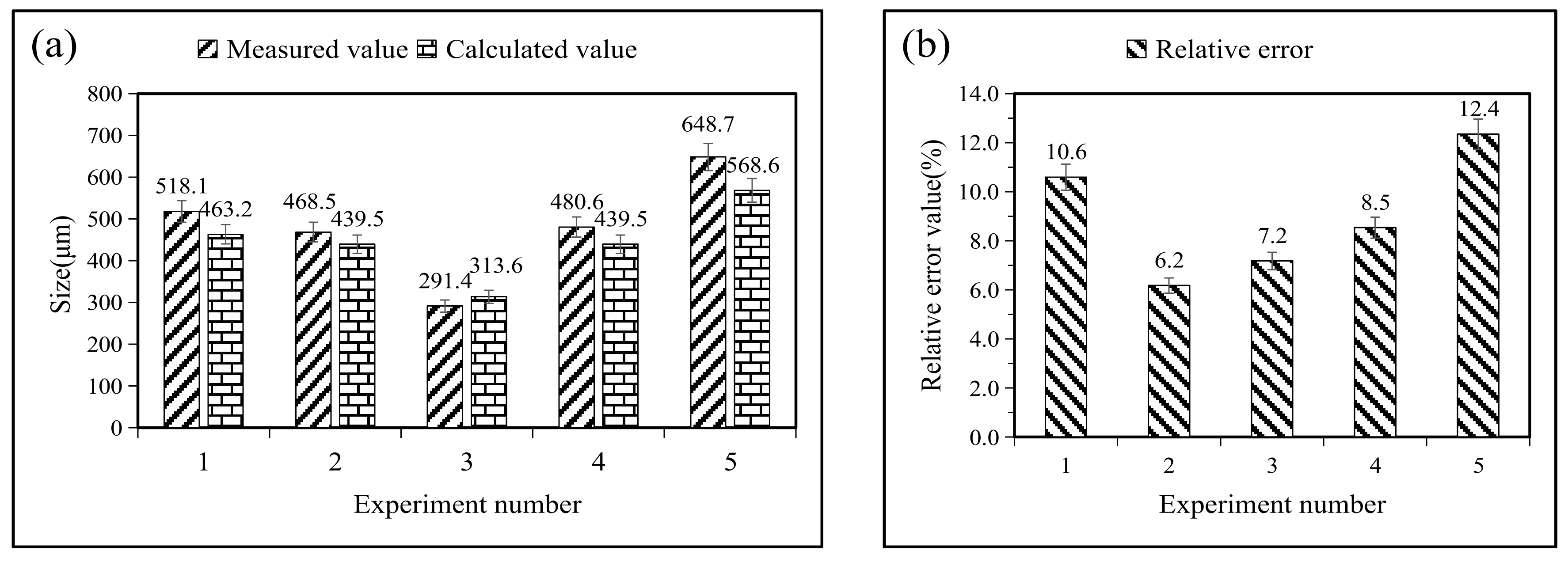
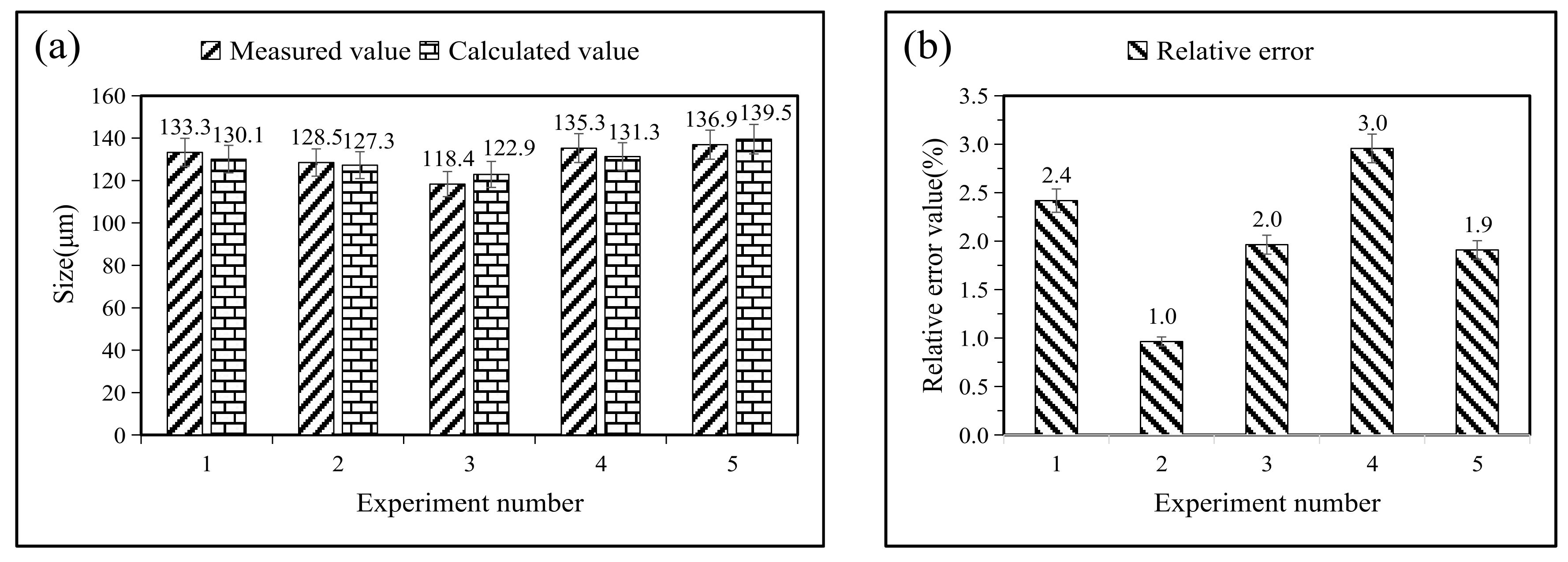
4.1. Regression Model of Groove Sizes

The exponential regression equation prediction model can not only describe the nonlinear characteristics but is also more accurate than the linear regression equation prediction in this analysis. Therefore, the exponential regression equation models are used in this paper to predict the groove width, groove depth and surface thermally affected zone width.
A quaternary regression equation is established, with the scanning times, scanning speed, laser power and pulse width as the main variable parameters in the nanosecond laser irradiation experiments:
B = C T N a 1 V a 2 P a 3 Q a 4
Taking the logarithm of both sides of the equation:
ln B = ln C T + a 1 ln N + a 2 ln V + a 3 ln P + a 4 ln Q
Assuming y = ln B , a 0 = ln C T , x 1 = ln N , x 2 = ln V , x 3 = ln P , x 4 = ln Q , the following regression equation is obtained:
y = a 0 + a 1 x 1 + a 2 x 2 + a 3 x 3 + a 4 x 4
Combining the 12 sets of experimental data, the regression models of the surface groove width, depth and surface thermally affected zone width perpendicular to the fiber direction and parallel to the fiber direction can be obtained, respectively. The models are as follows:
B c = e 5.14957 N 0.00746 V 0.18063 P 0.30043 Q 0.08039
D c = e 2.93539 N 0.22138 V 0.083208 P 0.67275 Q 0.55081
T c = e 7.74621 N 0.07555 V 0.24357 P 0.25138 Q 0.63478
B p = e 5.80636 N 0.03157 V 0.23114 P 0.10858 Q 0.13260
D p = e 4.79824 N 0.15866 V 0.17743 P 0.28071 Q 0.22467
T p = e 7.01935 N 0.16713 V 0.11779 P 0.24108 Q 0.10253
where B c is the regression model of the surface groove width perpendicular to the fiber direction, D c is the regression model of the surface groove depth perpendicular to the fiber direction, T c is the regression model of the surface thermally affected zone width perpendicular to the fiber direction, B p is the regression model of the surface groove width in the parallel fiber direction, D p is the regression model of the surface groove depth in the parallel fiber direction and T p is the regression model of the surface thermally affected zone width parallel to the fiber direction.
Five sets of experimental data are brought in, and the accuracy is verified by calculating the relative error of these regression models. The values of the four parameters of the laser treatment variables are substituted into Equations (6) to (11), and the relative errors are obtained from the following two equations:
e ( x * ) = x * x
where e ( x * ) is the absolute error, x * is the back-substitution value and x is the true value.
δ = e ( x * ) x × 100 %
where δ is the relative error. The results are obtained, as shown in Figure 10, Figure 11, Figure 12, Figure 13, Figure 14 and Figure 15.
After calculation, the average relative errors between the calculated value of the regression model equations and the actual measured value are shown in Table 5. In these regression models, the relative error values are all below 10%, which can truly reflect the influence of laser-processing parameters on the surface groove morphology. By analyzing the exponential value of these models, it can be concluded that the laser scanning speed and laser power have a greater impact on the surface groove width, followed by the laser pulse width, and the scanning times have the least impact.

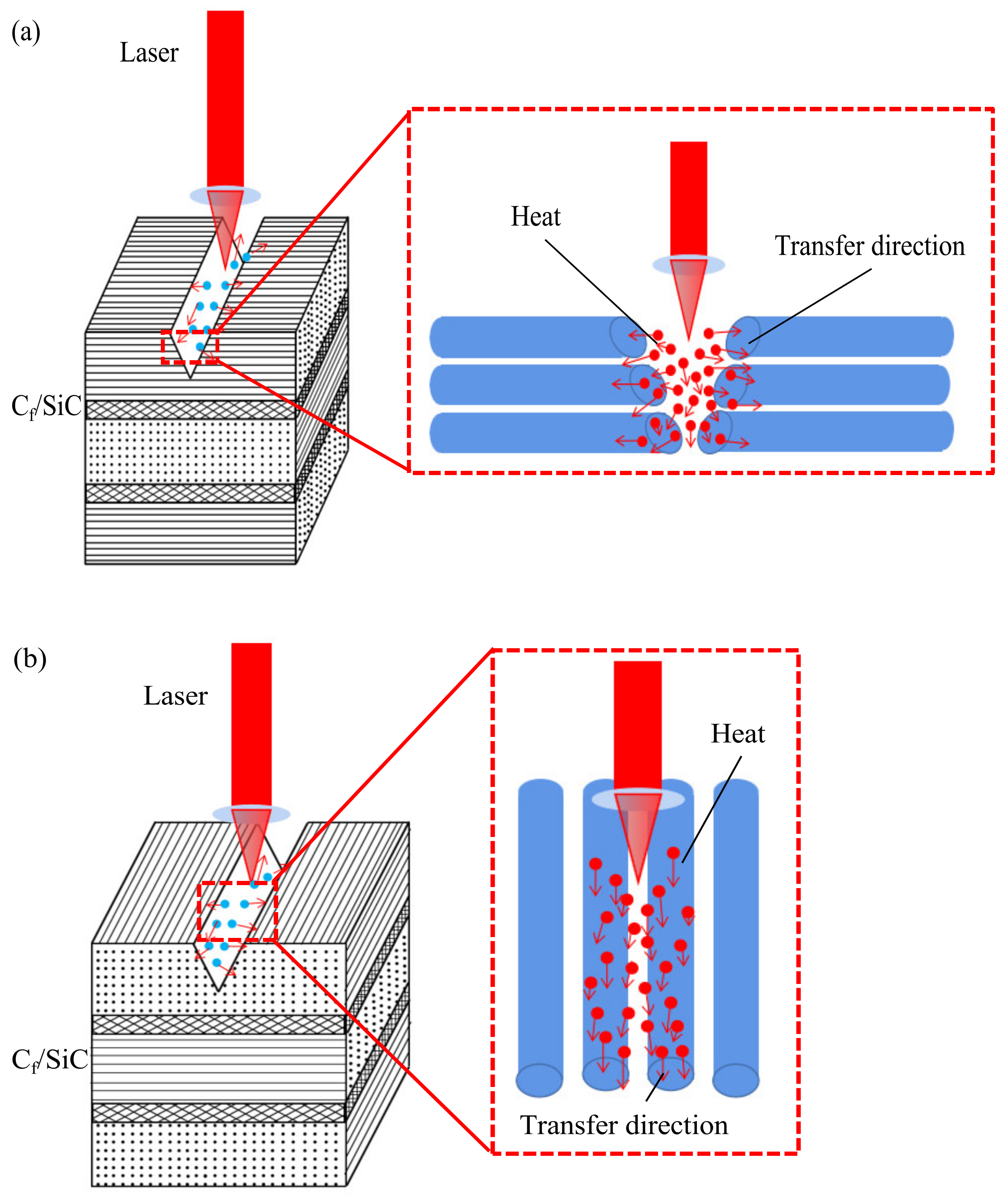
4.2. Mechanism of Laser Ablation

The principle of the laser processing of Cf/SiC composite materials is mainly to use a laser beam to irradiate the surface of the composite material. The SiC and carbon fibers are melted and evaporated or sublimated by heat. Therefore, on the surface of the processed sample, we can observe the two important measurement objects: the processing grooves and the thermally affected zone. However, during the laser processing, the flowing of the heat source between the tool and the workpiece will bring forces into the materials, such as surface tension and gravity. The material will partially splash under the combined action of these forces. This part of the molten material splashed into the non-processing zone cools to form a residue.
Under laser irradiation, the material obtains laser energy through nonlinear absorption. The composite materials melt to generate plasma of Si, C and O. In the air, they are easy to combine with the plasma. With the increment of the O content, more carbon fibers and the SiC matrix are oxidized [27]. The main products of the carbon fiber and SiC matrix oxidation are COx and SiOx. COx is a gas and is easily discharged. SiOx remains on the surface. After cooling, a heavy condensate is formed at the opening of the groove. Equations (14)–(19) are the main chemical reaction equations that occur in the processing zone. Many scholars, such as Pan [25] and Tong [42], also mentioned similar chemical reactions during laser ablation. Substances, such as heavy condensates and residues, are easily removed after cleaning. Due to the brittle and hard nature of the composite material, it will be subjected to internal stress and processing stress during processing. So, some fiber fractures are also observed.
C ( s ) + 1 2 O 2 ( g ) C O ( g )
C ( s ) + O 2 ( g ) C O 2 ( g )
S i ( s ) + 2 O 2 ( g ) S i O 2 ( l ) + C O 2 ( g )
S i C ( s ) + O 2 ( g ) S i O ( g ) + C O ( g )
2 S i C ( s ) + 3 O 2 ( g ) 2 S i O 2 ( l ) + 2 C O ( g )
S i O 2 ( l ) S i O 2 ( g )
Because of the different laser processing paths, the surface topography of the processed samples is different. Heat is easily transferred along the direction of carbon fibers, and the ablation behavior of composite materials is more complicated.

4.3. Fiber Topography for Grooves

There are many influencing factors regarding the processed surface of Cf/SiC composites, which make it difficult to observe the fiber pattern of the material within the observation groove scale. After cleaning the heavy condensates and debris on the surface of the composites, the groove morphology and fiber pattern at the fiber fracture can be observed. When the laser processing direction is perpendicular to the carbon fiber, as shown in Figure 16, neat and obvious fiber grooves can be seen. At the fiber grooves, the composite surface grooves do not show obvious processing differences from the other areas, and the overall processing grooves are relatively smooth. Figure 17 shows the end surface of the parallel direction. The laser processing route is not completely covered by the fiber direction, and obvious fiber grooves cannot be observed at the processed surface groove. When the processing route involves the fiber direction, the grooves will exhibit small changes, with a slight uneven phenomenon.

5. Conclusions

In this paper, the effects of nanosecond laser irradiation on Cf/SiC ceramic matrix composites have been investigated, and the effects of different laser processing parameters on the groove morphology and surface thermally affected zone have been analyzed in detail. Some of the conclusions drawn from the experimental results are as follows:
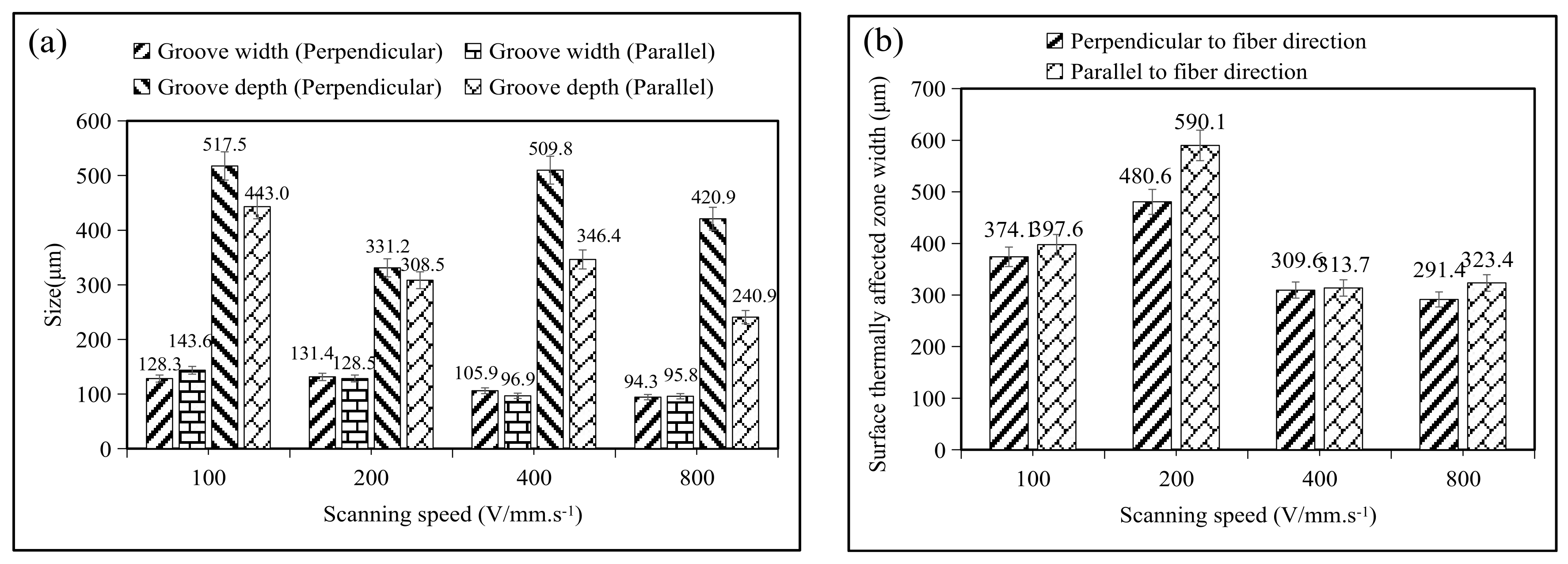
  • When the variation in laser parameters involves the laser scanning times and pulse width, the resulting groove width is small, at about ±10 μm. When the variation in parameters involves the laser scanning speed and laser power, the groove width decreases with the increment of the laser scanning speed and increases with the increment of the laser power.
  • The groove depth increases with the increment of the parameters in the processing experiments where the parameters are the laser scanning times and laser power. However, when the variable parameter is the laser scanning speed, the faster the speed, the shallower the groove depth. In the machining experiments where the variable parameter is the pulse width, the groove depth shows different trends in different machining path directions.
  • The variation trend of the surface thermally affected zone width is similar to that of the laser irradiation processing experiment where the variable parameters of the laser are the scanning times and laser scanning speed. With the increment of the parameters, the width of the surface thermal influence area first increases and then decreases. When the variable parameter is the laser power, the surface thermally affected zone width decreases with the increment of power. When the variable parameter is the laser pulse width, different processing path directions show different trends.
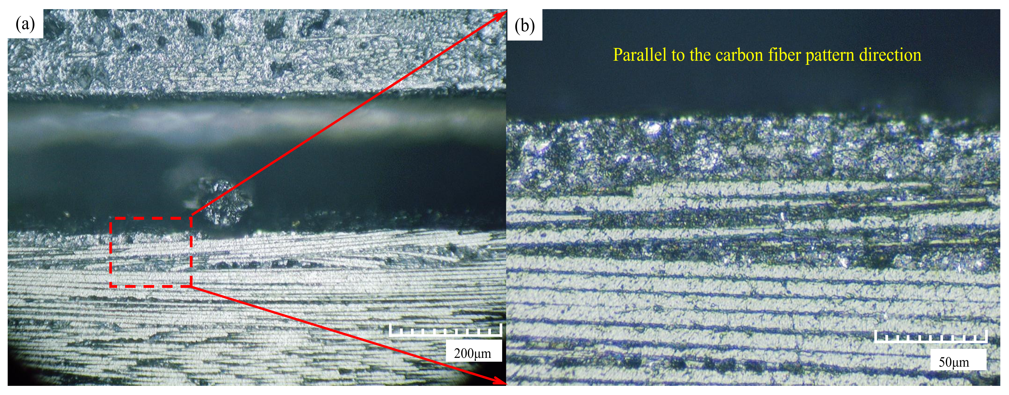
  • The fiber direction has an impact on laser processing, but there is an opposite trend only when individual parameters change. In addition, the groove morphology at the fiber fracture is affected by the fiber texture. The appearance of carbon fibers in the laser processing of parallel fiber textures will make the processing groove slightly uneven. The fiber grooves are not obvious and can hardly be observed. During processing, the fiber grooves are obviously clear.
  • Based on the multivariate nonlinear regression equation, a regression model with the laser scanning times, scanning speed, laser power and pulse width as the main variables is established. The model can truly reflect the influence of laser processing parameters on the surface groove morphology of Cf/SiC. It is concluded that the laser scanning speed and laser power have a greater impact on the surface groove width, followed by the laser pulse width. The laser scanning times cause a minimal impact.
  • In this paper, the laser machining process is mainly understood from the perspective of the ablation mechanism. However, the effect of the mechanical properties of composite materials and force variation on laser-assisted processing should also be considered in practical laser processing. The ablated process can be applied as a pre-process for the laser-assisted grinding of this type of material, which can substantially improve the machining efficiency.

Author Contributions

C.W. designed the whole conception and theoretical analysis. T.Z. and F.L. conducted the experiments and wrote the paper. Y.L. and S.Y.L. helped in polishing and revising the manuscript. All authors have read and agreed to the published version of the manuscript.

Funding

This work is supported by the National Natural Science Foundation of China (No. 52005098 & 51905498) and the Shanghai Natural Science Foundation (22ZR1402400). The authors wish to express their gratitude for the generous support.

Data Availability Statement

Not applicable.

Acknowledgments

Not applicable.

Conflicts of Interest

The authors declare that they have no known competing financial interest or personal relationships that could have appeared to influence the work reported in this paper.

References

  1. Liu, Y.; Quan, Y.; Wu, C.J.; Ye, L.Z.; Zhu, X.J. Single diamond scribing of SiCf/SiC composite: Force and material removal mechanism study. Ceram. Int. 2021, 47, 27702–27709. [Google Scholar] [CrossRef]
  2. Hu, J.H.; Tang, J.L.; Li, T.; Xu, L.L.; Lin, B.; Yang, M.J.; Wang, Y.Y.; Li, H.Y.; Zhang, Z.H. Research Progress on Etching Modification of Carbon Fiber and Aramid Fiber and the Interface Bonding Performance of Their Composite Materials. Surf. Technol. 2021, 50, 94–116. [Google Scholar]
  3. Guo, M.X.; Tao, J.B.; Wu, C.J.; Luo, C.; Lin, Z.J. High-speed grinding fracture mechanism of Cf/SiC composite considering interfacial strength and anisotropy. Ceram. Int. 2023, 49, 2600–2612. [Google Scholar] [CrossRef]
  4. Zhou, W.W.; Wang, J.Q.; Zhao, J.; Liu, Y. Experimental research on single abrasive grain scratch SiCf/SiC ceramic matrix composite. Diam. Abras. Eng. 2021, 41, 51–57. [Google Scholar]
  5. Diaz, G.G.; Luna, Z.; Liao, Z.; Axinte, D. The new challenges of machining Ceramic Matrix Composites (CMCs): Review of surface integrity. Int. J. Mach. Tools Manuf. 2019, 139, 24–36. [Google Scholar] [CrossRef]
  6. Wang, J.Q.; Yan, Y.D.; Li, C.; Geng, Y.Q. Material removal mechanism and subsurface characteristics of silicon 3D nanomilling. Int. J. Mech. Sci. 2023, 242, 108020. [Google Scholar] [CrossRef]
  7. Wu, C.J.; Pang, J.Z.; Li, B.Z. High Speed Grinding of HIP-SiC Ceramics on Transformation of Microscopic Features. Int. J. Adv. Manuf. Technol. 2019, 102, 1913–1921. [Google Scholar] [CrossRef]
  8. Liu, G.S.; Liu, Y.X.; Bian, D.; Zhao, Y.W. Tribological Properties of Graphene Oxide Grafted Carbon Fiber and Its Resin Coating under Different Loads. Surf. Technol. 2021, 50, 62–69. [Google Scholar]
  9. Liu, S.; Xiao, G.J.; Lin, O.C.; He, Y.; Song, S.Y. A new one-step approach for the fabrication of microgrooves on Inconel 718 surface with microporous structure and nanoparticles having ultrahigh adhesion and anisotropic wettability: Laser belt processing. Appl. Surf. Sci. 2023, 607, 15510801–15510818. [Google Scholar] [CrossRef]
  10. Qu, S.S.; Yao, P.; Gong, Y.D. Modelling and grinding characteristics of unidirectional C-SiCs. Ceram. Int. 2022, 48, 8314–8324. [Google Scholar] [CrossRef]
  11. Li, C.; Hu, Y.X.; Zhang, F.H.; Geng, Y.Q.; Meng, B.B. Molecular dynamics simulation of laser assisted grinding of GaN crystals. Int. J. Mech. Sci. 2023, 239, 107856. [Google Scholar] [CrossRef]
  12. Shu, C.S.; Su, Q.T.; Li, M.H.; Wang, Z.B.; Yin, S.H.; Huang, S. Fabrication of extreme wettability surface for controllable droplet manipulation over a wide temperature range. Int. J. Extrem. Manuf. 2022, 4, 045103. [Google Scholar] [CrossRef]
  13. Yu, J.W.; Fei, Q.G.; Zhang, P.W.; Li, Y.B.; Chen, Q. Fatigue Life of a 2.5D C/SiC Composite Under Tension–Tension Cyclic Loading: Experimental Investigation and Sensitivity Analysis. Acta Mech. Solida Sin. 2021, 34, 277–285. [Google Scholar] [CrossRef]
  14. Li, C.; Piao, Y.C.; Zhang, F.H.; Zhang, Y.; Hu, Y.X.; Wang, Y.F. Understand anisotropy dependence of damage evolution and material removal during nanoscratch of MgF2 single crystals. Int. J. Extrem. Manuf. 2023, 5, 015101. [Google Scholar] [CrossRef]
  15. Puertas, I.; Luis, C.J. A study on the electrical discharge machining of conductive ceramics. J. Mater. Process. Technol. 2004, 153–154, 1033–1038. [Google Scholar] [CrossRef]
  16. Sun, Y.; Jin, L.Y.; Gong, Y.D.; Wen, X.L.; Yin, G.Q.; Wen, Q.; Tang, B.J. Experimental evaluation of surface generation and force time-varying characteristics of curvilinear grooved micro end mills fabricated by EDM. J. Manuf. Process. 2022, 73, 799–814. [Google Scholar] [CrossRef]
  17. Wang, Z.; Wang, J.T.; Song, H.W.; Yuan, W.; Liu, Y.W.; Ma, T.; Huang, C.G. Laser ablation behavior of C/SiC composites subjected to transverse hypersonic airflow. Corros. Sci. 2021, 183, 109345. [Google Scholar] [CrossRef]
  18. Zhai, C.T.; Xu, J.K.; Hou, Y.G.; Sun, G.B.; Zhao, B.B.; Yu, H. Effect of fiber orientation on surface characteristics of C/SiC composites by laser-assisted machining. Ceram. Int. 2022, 48, 6402–6413. [Google Scholar] [CrossRef]
  19. Lambiase, F.; Genna, S.; Leone, C.; Paoletti, A. Laser-assisted direct-joining of carbon fibre reinforced plastic with thermosetting matrix to polycarbonate sheets. Opt. Laser Technol. 2017, 94, 45–58. [Google Scholar] [CrossRef]
  20. Wei, J.Y.; Yuan, S.M.; Zhang, J.Q.; Zhou, N.; Zhang, W.; Li, J.B.; An, W.Z.; Gao, M.X.; Fu, Y.Z. Removal mechanism of SiC/SiC composites by underwater femtosecond laser ablation. J. Eur. Ceram. Soc. 2022, 42, 5380–5390. [Google Scholar] [CrossRef]
  21. Yang, G.F.; Liu, L.; Xia, H.Y.; Cui, J. Experimental Study of Ice Suppression Characteristics of TC4 Microstructure Surface Induced by Nanosecond Laser. Surf. Technol. 2021, 50, 93–102. [Google Scholar]
  22. Zhang, X.; Huang, T.; Xiao, R.S. Effect of Crystal Orientation on High Power Green Femtosecond Laser Processing of Single Crystal Silicon. Surf. Technol. 2021, 50, 362–371. [Google Scholar]
  23. Dong, Z.; Yan, Y.; Peng, G.; Li, C.; Geng, Y.Q. Effects of sandwiched film thickness and cutting tool water contact angle on the processing outcomes in nanoskiving of nanowires. Mater. Des. 2023, 225, 111438. [Google Scholar] [CrossRef]
  24. Zhai, Z.Y.; Zhang, Y.C.; Cui, Y.H.; Zhang, Y.F.; Zeng, Q.R. Investigations on the ablation behavior of C/SiC under femtosecond laser. Optik 2020, 224, 165719. [Google Scholar] [CrossRef]
  25. Pan, S.N.; Li, Q.Y.; Xian, Z.K.; Su, N.G.; Zeng, F.Z. The Effects of Laser Parameters and the Ablation Mechanism in Laser Ablation of C/SiC Composite. Materials 2019, 12, 3076. [Google Scholar] [CrossRef] [Green Version]
  26. Hu, W.Q.; Shin, Y.C.; King, G.B. Micromachining of Metals, Alloys, and Ceramics by Picosecond Laser Ablation. J. Manuf. Sci. Eng. 2010, 132, 011009. [Google Scholar] [CrossRef]
  27. Liu, C.; Zhang, X.Z.; Wang, G.F.; Wang, Z.F.; Gao, L. New ablation evolution behaviors in micro-hole drilling of 2.5D Cf/SiC composites with millisecond laser. Ceram. Int. 2021, 47, 29670–29680. [Google Scholar] [CrossRef]
  28. Zhang, C.Y.; Wang, X.W.; Liu, Y.S. Tensile fatigue of a 2.5D-C/SiC composite at room temperature and 900 degrees C. Mater Design. 2013, 49, 814–819. [Google Scholar] [CrossRef]
  29. Deng, Y.; Zhou, Y.F.; Zhang, Y.M.; Chen, D.K.K.; Zhou, X.L. Numerical and experimental analysis of nanosecond laser ablation of SiC. Mater. Sci. Semicond. Process. 2022, 151, 107020. [Google Scholar] [CrossRef]
  30. Liu, Y.S.; Wang, J.; Li, W.N.; Wang, C.H.; Zhang, Q.; Yang, X.J.; Cheng, L.F. Effect of energy density and feeding speed on micro-holes drilling in SiC/SiC composites by picosecond laser. Int. J. Adv. Manuf. Technol. 2016, 84, 1917–1925. [Google Scholar] [CrossRef]
  31. Wang, J.T.; Ma, Y.Z.; Liu, Y.W.; Yuan, W.; Song, H.W.; Huang, C.G.; Yin, X.W. Experimental investigation on laser ablation of C/SiC composites subjected to supersonic airflow. Opt. Laser Technol. 2019, 113, 399–406. [Google Scholar] [CrossRef] [Green Version]
  32. Liu, Y.S.; Wang, C.H.; Li, W.N.; Yang, X.J.; Zhang, Q.; Cheng, L.F.; Zhang, L.T. Effect of energy density on the machining character of C/SiC composites by picosecond laser. Appl. Phys. A 2014, 116, 1221–1228. [Google Scholar] [CrossRef]
  33. Vadim, A.; Fabrice, L.; Alfred, E.; Lionel, M.; Gildas, L.; Bernard, D. An experimental method to assess the thermo-mechanical damage of CFRP subjected to a highly energetic 1.07 μm-wavelength laser irradiation. Compos. Part B 2016, 92, 326–331. [Google Scholar]
  34. Zhai, Z.Y.; Wang, W.J.; Zhao, J.; Mei, X.S.; Wang, K.D.; Wang, F.C.; Yang, H.Z. Influence of surface morphology on processing of C/SiC composites via femtosecond laser. Compos. Part A Appl. Sci. Manuf. 2017, 102, 117–125. [Google Scholar] [CrossRef]
  35. Wu, C.J.; Li, B.Z.; Liu, Y.; Liang, S. Surface roughness modeling for grinding of silicon carbide ceramics considering co-existence of brittleness and ductility. Int. J. Mech. Sci. 2017, 133, 167–177. [Google Scholar] [CrossRef]
  36. Liu, C.; Zhang, X.Z.; Gao, L.; Jiang, X.Z.; Wang, X.D.; Yang, T. Study on damage characteristics and ablation mechanism in fiber laser trepan drilling of 2.5D Cf/SiC composites. Int. J. Adv. Manuf. Technol. 2021, 117, 3647–3660. [Google Scholar] [CrossRef]
  37. Dang, X.L.; Yin, X.W.; Fan, X.M.; Ma, Y.Z.; Wang, J.T.; Ju, P.F.; Song, H.W. Microstructural evolution of carbon fiber reinforced SiC-based matrix composites during laser ablation process. J. Mater. Sci. Technol. 2019, 35, 2919–2925. [Google Scholar] [CrossRef]
  38. Jiao, H.W.; Chen, B.; Deng, Z.H. Influence of laser parameters on processing microgrooves of 2.5-dimensional C/SiC composites via nanosecond laser. Int. J. Adv. Manuf. Technol. 2022, 118, 85–101. [Google Scholar] [CrossRef]
  39. Zhang, R.H.; Li, W.N.; Liu, Y.S.; Wang, J.; Yang, X.J.; Cheng, L.F. Machining parameter optimization of C/SiC composites using high power picosecond laser. Appl. Surf. Sci. 2015, 330, 321–331. [Google Scholar] [CrossRef]
  40. Liu, Y.S.; Wang, C.H.; Li, W.N.; Wang, C.H.; Zhang, Q.; Yang, X.J.; Cheng, L.F. Effect of energy density and feeding speed on micro-hole drilling in C/SiC composites by picosecond laser. J. Mater. Process. Technol. 2014, 214, 3131–3140. [Google Scholar] [CrossRef]
  41. Cheng, L.F.; Xu, Y.D.; Zhang, Q.; Zhang, L.T. Thermal diffusivity of 3D C/SiC composites from room temperature to 1400 °C. Carbon 2003, 41, 701–711. [Google Scholar]
  42. Tong, Y.G.; Bai, S.X.; Zhang, H.; Ye, Y.C. Laser ablation behavior and mechanism of C/SiC composite. Ceram. Int. 2013, 39, 6813–6820. [Google Scholar] [CrossRef]
Figure 1. Structure of the 2.5-dimensional Cf/SiC composite material ((a). 2.5D structure diagram; (b). microscope figure).
Crystals 13 00223 g001
Figure 2. Experimental flow chart ((a). surface polishing; (b). ultrasonic wash; (c). dryer; (d). laser processing; (e). 3D microscope observation; (f). result analysis).
Crystals 13 00223 g002
Figure 3. Laser processing of Cf/SiC composites ((a). processing macrograph; (b). processing direction diagram; (c). pictures during experimental processing).
Crystals 13 00223 g003
Figure 4. 3D-microscopic image with measured sizes ((a). thermal affected width and groove width; (b). groove depth).
Crystals 13 00223 g004
Figure 5. Effect of laser scanning times on the composite surface groove ((a). variation in groove width and depth; (b). variation in thermally affected zone width).
Crystals 13 00223 g005
Figure 6. Effect of the scanning speed on the composite surface groove ((a). variation in groove width and depth; (b). variation in thermally affected zone width).
Crystals 13 00223 g006
Figure 7. Effect of laser power on the groove of the composite surface ((a). variation in groove width and depth; (b). variation in thermally affected zone width).
Crystals 13 00223 g007
Figure 8. The heat transfer affected by the anisotropy structure ((a). perpendicular to fiber direction; (b). parallel to fiber direction).
Crystals 13 00223 g008
Figure 9. Effect of the pulse width on the composite surface groove ((a). variation in groove width and depth; (b). variation in thermally affected zone width).
Crystals 13 00223 g009
Figure 10. Error verification of Equation (6) ((a). comparison of measureed value and calculated value; (b). corresponding relative error).
Crystals 13 00223 g010
Figure 11. Error verification of Equation (7) ((a). comparison of measureed value and calculated value; (b). corresponding relative error).
Crystals 13 00223 g011
Figure 12. Error verification of Equation (8) ((a). comparison of measureed value and calculated value; (b). corresponding relative error).
Crystals 13 00223 g012
Figure 13. Error verification of Equation (9) ((a). comparison of measureed value and calculated value; (b). corresponding relative error).
Crystals 13 00223 g013
Figure 14. Error verification of Equation (10) ((a). comparison of measureed value and calculated value; (b). corresponding relative error).
Crystals 13 00223 g014
Figure 15. Error verification of Equation (11) ((a). comparison of measureed value and calculated value; (b). corresponding relative error).
Crystals 13 00223 g015
Figure 16. Vertical fiber direction processing end surface ((a). the groove morphology at the fiber fracture; (b). partial enlargement of the picture).
Crystals 13 00223 g016
Figure 17. Parallel fiber direction processing end surface ((a). the groove morphology at the fiber fracture; (b). partial enlargement of the picture).
Crystals 13 00223 g017
Table 1. Material characteristics of the 2.5D Cf/SiC [34].
Properties (at Room Temperature)Parmeters
Diameter of carbon fiber7.6 μmPorosity17%
Density1.7 g/cm3Size15 × 15 × 15 mm3
Fiber volume fraction40~50%Thermal conductivity8–10 W/m·k
Fiber mass fraction27.27~36%Thermal expansivity2–6 × 10⁻⁶ K−1
Table 2. Characteristics of the carbon fiber and SiC matrix [35,36].
PropertiesSiC CeramicsCarbon Fiber
Thermal conductivity (W/m·k)185Radial: 5; axial: 50
Specific heat (J/kg·K)800710
Vaporization temperature (K)27003550
Latent heat for vaporization (MJ/kg)19.8343
Density (kg/m3)32201780
Young’s modulus (GPa)450Radial: 15; axial: 230
Shear modulus (GPa)193Radial: 7; axial: 27
Table 3. Nanosecond laser parameters.
Laser EquipmentPoplar-355
wavelength355 nmbeam directivity<25 μrad
output power>5 W@50 kHZlaser head size500 × 185 × 147 mm3
single pulse energy>125 μJ@40 kHZdivergence angle of light spots≤1 mrad (with a beam expansion)
repeat frequency rate20–200 kHZworking temperature10–35 °C
pulse width16 ± 2 ns@50 kHZworking humidity<65%
power stability≤3% rmscooling-down methodWater
pulse stability≤3% rmsbeam diameter<8 mm
Table 4. Experimental processing parameters.
Serial NumberScanning Times (N)Scanning Speed (V/mm.s−1)Laser Power (P/W)Pulse Width (Q/μs)Wavelength (nm)Cooling-Down Method
1100200150.3355water
2200200150.3355water
3400200150.3355water
4800200150.3355water
51200200150.3355water
6400100150.3355water
7400200150.3355water
8400400150.3355water
9400800150.3355water
1040020050.3355water
11400200100.3355water
12400200150.3355water
13400200200.3355water
14400200150.15355water
15400200150.2355water
16400200150.25355water
17400200150.3355water
Table 5. Relative error.
Regression Model B c D c T c B p D p T p
Relative error5.2%7.1%9.0%2.0%8.6%9.2%
Disclaimer/Publisher’s Note: The statements, opinions and data contained in all publications are solely those of the individual author(s) and contributor(s) and not of MDPI and/or the editor(s). MDPI and/or the editor(s) disclaim responsibility for any injury to people or property resulting from any ideas, methods, instructions or products referred to in the content.

