
Role of Persistent Slip Bands and Persistent Slip Markings in Fatigue Crack Initiation in Polycrystals

Institute of Physics of Materials, Czech Academy of Sciences, Žižkova 22, 616 00 Brno, Czech Republic
Crystals 2023, 13(2), 220; https://doi.org/10.3390/cryst13020220
Submission received: 6 January 2023
/
Revised: 19 January 2023
/
Accepted: 20 January 2023
/
Published: 25 January 2023
(This article belongs to the Special Issue Dislocation Mechanics of Crystal/Polycrystal Mechanical Strength Properties)
Abstract
:The cyclic plastic deformation of polycrystals leads to the inhomogeneous distribution of the cyclic plastic strain. The cyclic plastic strain is concentrated in thin bands, called persistent slip bands (PSBs). The dislocation structure of these bands generally differs from the matrix structure and is characterized by alternating dislocation-rich and dislocation-poor regions. The mechanisms of the dislocation motion in the PSBs and the formation of the point defects and their migration are quantitatively described. It is shown that, due to localized cyclic plastic straining in the PSBs, persistent slip markings (PSMs) are produced where the PSBs emerge on the surface. They typically consist of a central extrusion accompanied by one or two parallel intrusions. The deep intrusion is equivalent to the crack-like surface defect. The concentration of the cyclic strain in the tip of an intrusion leads to intragranular fatigue crack initiation. The mechanism of the early crack growth in the primary slip plane is proposed and discussed. Numerous PSMs are produced on the surface of the cyclically loaded materials. PSMs contribute to the formation of the surface relief, as well as the relief on the grain boundary. PSMs from one grain impinging the grain boundary are sufficient to create sharp relief on the grain boundary. Void-like defects weaken the grain boundary cohesion and extra material push both grains locally apart. The conditions necessary for the weakening of the grain boundary are enumerated and examples of grain boundary crack initiations are shown. The relevant parameters affecting grain boundary initiation are identified and discussed. The collected experimental evidence and analysis is mostly based on the papers published by the author and his colleagues in the Institute of Physics of Materials in Brno.
1. Introduction
Most structural materials are produced in the form of polycrystals; however, in some specific cases, a single crystalline form is important, e.g., in order to reach higher creep or fatigue strength. The cyclic loading of polycrystals results in cyclic strain. Dependending on the character of the applied stress cyclic strain has two components: unidirectional, resulting in mean strain, and true cyclic strain, which is approximately symmetric. In cycling with constant stress or strain amplitude, we can characterize cyclic loading by the stress and strain amplitude, σa and εa, and the mean stress and strain, σm and εm. In the majority of cases, repeated cyclic stress and strain, which can be characterized by the stress and strain amplitudes, cause the development of fatigue damage, leading to the initiation and growth of fatigue cracks and, finally, to the fracture of a specimen or structure.
The relationship between cyclic stress and strain has been the subject of intensive study since the identification of the fatigue phenomenon. Bairstow, in 1911 [1], studied the variations of the elastic limit of iron and steel in cyclic loading and recorded hysteresis loops. Masing, in 1923 [2], analyzed the hardening within the hysteresis loop and confirmed the role of “hidden” elastic stresses in the explanation of the shape of the hysteresis loop. His analysis led, much later, to the statistical theory of the hysteresis loop [3]. Using statistical theory, the probability density function of internal critical stresses and effective stress can be determined during cyclic loading.
Cyclic strain has two components: the elastic and the plastic strain. Elastic strain is fully reversible, it is proportional to the stress and does not contribute to damage, while plastic strain is mostly irreversible and results in changes to the form of the stressed body. As the amplitude of the plastic strain is small, the changes in the internal structure within a loading cycle are also small. However, due to a large number of cycles, applied cumulative changes can be important and can result in the formation of surface relief and, finally, in the initiation of fatigue cracks.
In order to find the mechanisms of fatigue damage, both the internal structure and surface evolution of the cycled materials has been studied. Numerous monographs and review articles have been devoted to revealing the internal structure and evolution of the surface damage in fatigued metals and alloys (e.g., [4,5,6,7,8,9,10]). New technology applied to the investigation of damage mechanisms, such as high resolution TEM, AFM, EBSD, high resolution SEM in combination with FIB, bring a more detailed insight into the processes of cyclic plastic straining, the internal structure and the surface relief development. This has allowed us to attain a true picture of the processes leading to fatigue damage in metal polycrystals.
2. Cyclic Strain Localization and Surface Evolution in Cyclic Straining
Indirect evidence on the inhomogeneous cyclic deformation of polycrystals has been obtained as early as 1903, by Ewing Humfrey [11], who studied the surface of polycrystalline Swedish iron cyclically strained in rotating bending with constant stress amplitudes. These slip markings, which after removal by etching reappeared during further cyclic loading, were later called persistent slip markings (PSMs) (originally, they were called persistent slip bands (PSBs)) [12,13]. Only later, with the appearance of transmission electron microscopy, the three-dimensional dislocation structure of the bands responsible for cyclic slip—PSBs—was found, originally in copper single crystals [14,15], and later, also in copper polycrystals [16].
The cyclic loading of polycrystalline specimens leads to the formation of the pronounced surface relief. Optical microscopy cannot reveal all the details of the surface relief. Higher resolution can be obtained using scanning electron microscopy (SEM), atomic force microscopy (AFM) or a combination of transmission electron microscopy (TEM) with focused ion beam (FIB). Figure 1 shows the surface profile in two neighbor grains of copper polycrystal, cycled at room temperature with a constant strain amplitude 1 × 10⁻³ to 8% of the fatigue life. The surface relief is already well developed at this early stage. PSMs appear in both grains, showing that cyclic plastic strain is localized in the PSBs, and the rest of the material is cyclically strained only elastically. Elastically strained materials produce a flat surface, identical to that before cyclic loading. Localized cyclic plastic strain produces pronounced surface relief (PSMs) in the form of extrusions and intrusions.
2.1. Experimental Studies of Cyclic Strain Localization
The localization of cyclic plastic deformation has been detected on the surface of Swedish iron at the onset of the previous century, by Ewing and Humfrey [11]. Using an optical microscope, they observed distinct slip lines, which, during further cyclic loading, broadened and were upheaved above the level of the grain or fell below it. Localized slip bands have been frequently and closely observed in polycrystalline copper. The first observation of the exudation of the material from slip bands during fatigue of aluminium-copper alloys was reported by Forsyth [17]. Cottrell and Hull [18] obtained detailed pictures of both extrusions and intrusions in polycrystalline copper using replica technique. Early experiments on cyclic strain localization were reviewed by Man et al. [19] and Antolovich and Armstrong [20]. These observations indicated the inhomogeneous cyclic deformation with the concentration of the plastic strain into the bands of cyclic slip that were later called PSBs. Numerous papers have been devoted to the study of the shape and evolution of PSMs on the surface of fatigued single and polycrystals [12,21,22,23,24,25]. The dislocation structure of the PSBs was originally revealed in copper single crystals [14,15,26] and, later, also in polycrystals [16,27].
PSMs, their shape and their growth have frequently been studied using optical microscopy [13,17,28], and later using atomic force microscopy (AFM) [29,30,31,32]. AFM can be used for the study of the growth of extrusions and, using replica technique, also intrusions. The distortions of the true shape of PSMs, due to finite dimensions of AFM tip and the inclination of the primary slip plane to the surface, can be encountered [33]. The true shape of PSMs can be assessed using FIB cuts [34,35,36,37].
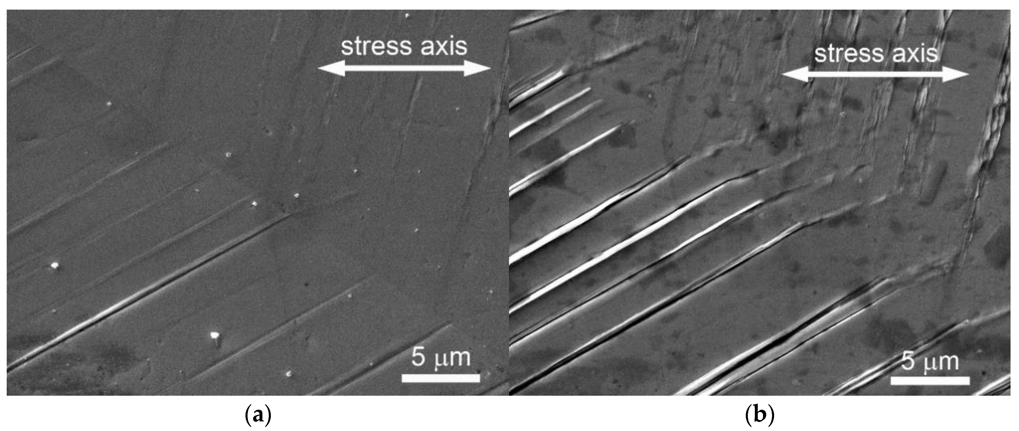
Recent studies on copper polycrystals cycled in symmetrical tension/compression with a constant strain amplitude εa or plastic strain amplitude εap reveal PSMs in individual grains, consisting of extrusions and, often, extrusions and parallel intrusions (Figure 1). The density, shape and the height of PSMs depend on the applied strain amplitude. They develop during cycling. The SEM image in Figure 1 shows the surface of the grain of polycrystalline copper cycled with a low strain amplitude in two phases of the fatigue life. PSMs are already developed at the early stage of fatigue life (N = 5% Nf, Figure 1a). They start mostly as extrusions and extend up to the grain boundary. At 5% of the fatigue life, only one PSM, shown in Figure 1a, consists of a pronounced extrusion and parallel intrusion. At half of the fatigue life (Figure 1b), the majority of these PSMs consist of extrusions and parallel intrusions. It is apparent that there is a tendency to extend the slip in the neighbor grain along some secondary slip system.
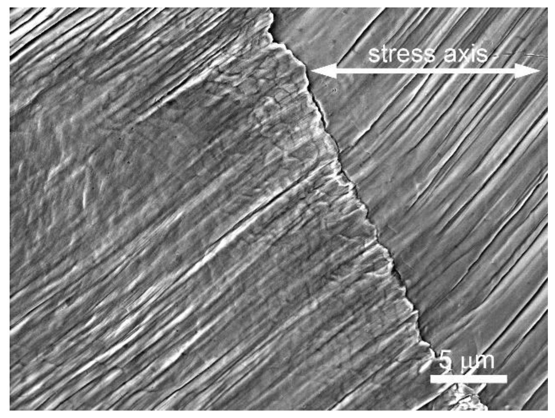
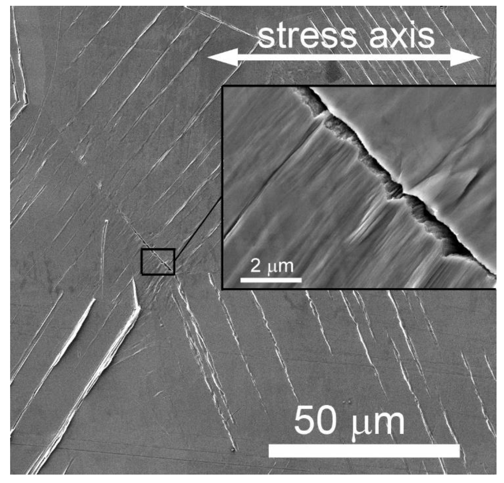
Cycling with high strain amplitudes produces a surface with a high density of PSMs (Figure 2). They again extend up to the grain boundary. Due to the different orientations of the neighbor grain, in most cases, the slip does not continue to the neighbor grain. The slip systems in the other grain produces PSMs corresponding to the primary slip system in that grain. In high amplitude cycling, the high density of the PSMs results in an alternation of extrusions and intrusions.
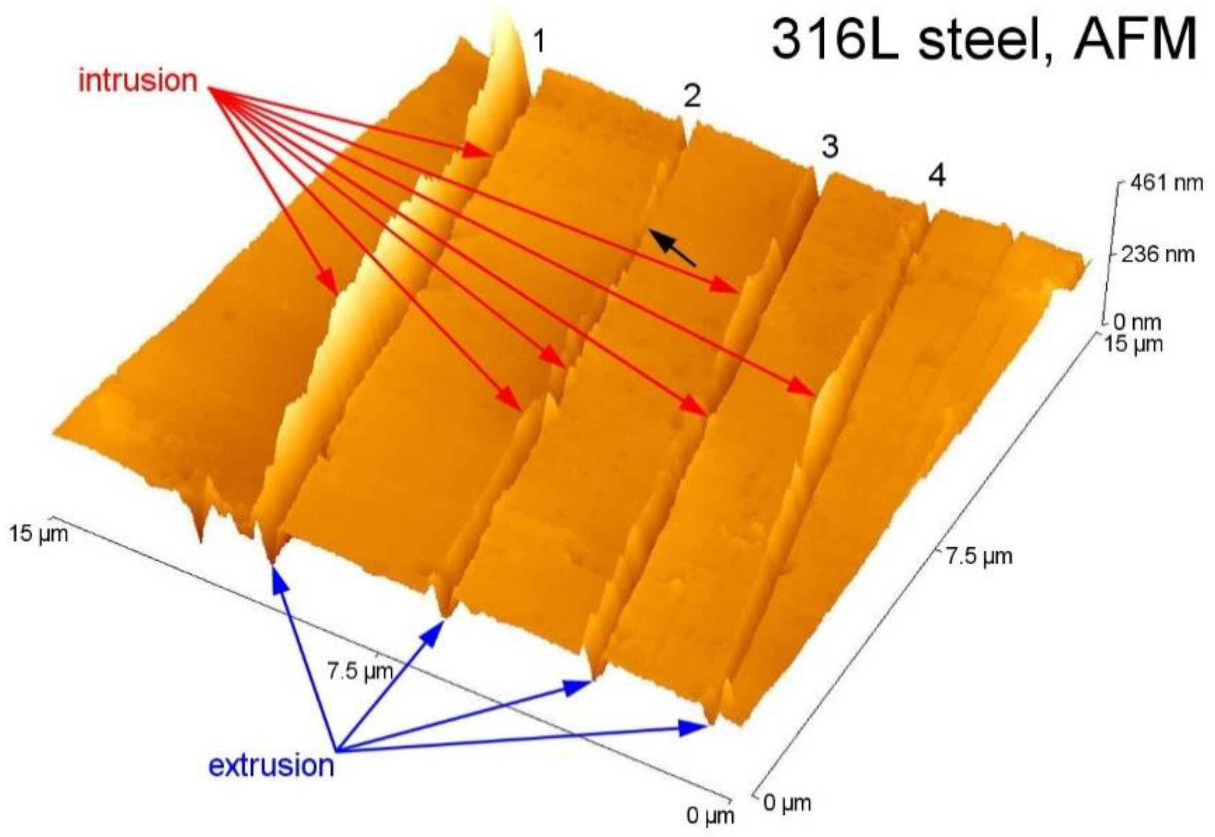
SEM observations cannot yield the three-dimensional picture of PSMs. The use of atomic force microscopy (AFM) [30,38,39,40] allows the information in three dimensions to be obtained. Due to the finite dimensions of the AFM tip and the inclination of the extrusion and intrusion to the surface, some distortion of the real shape of PSMs appears [33]. In order to detect intrusions using AFM, the replica technique has been adopted [31]. Figure 3 shows the surface of 316L steel cycled with a constant plastic strain amplitude to 4.3% of fatigue life. In this picture, the extrusion shape is distorted due to the dimensions of the tip, but the intrusions are imaged without AFM distortion. The extrusions are accompanied by intrusions, and one of them is very deep. Nevertheless, some doubts can arise in terms of whether theses intrusions are not already stage I cracks.
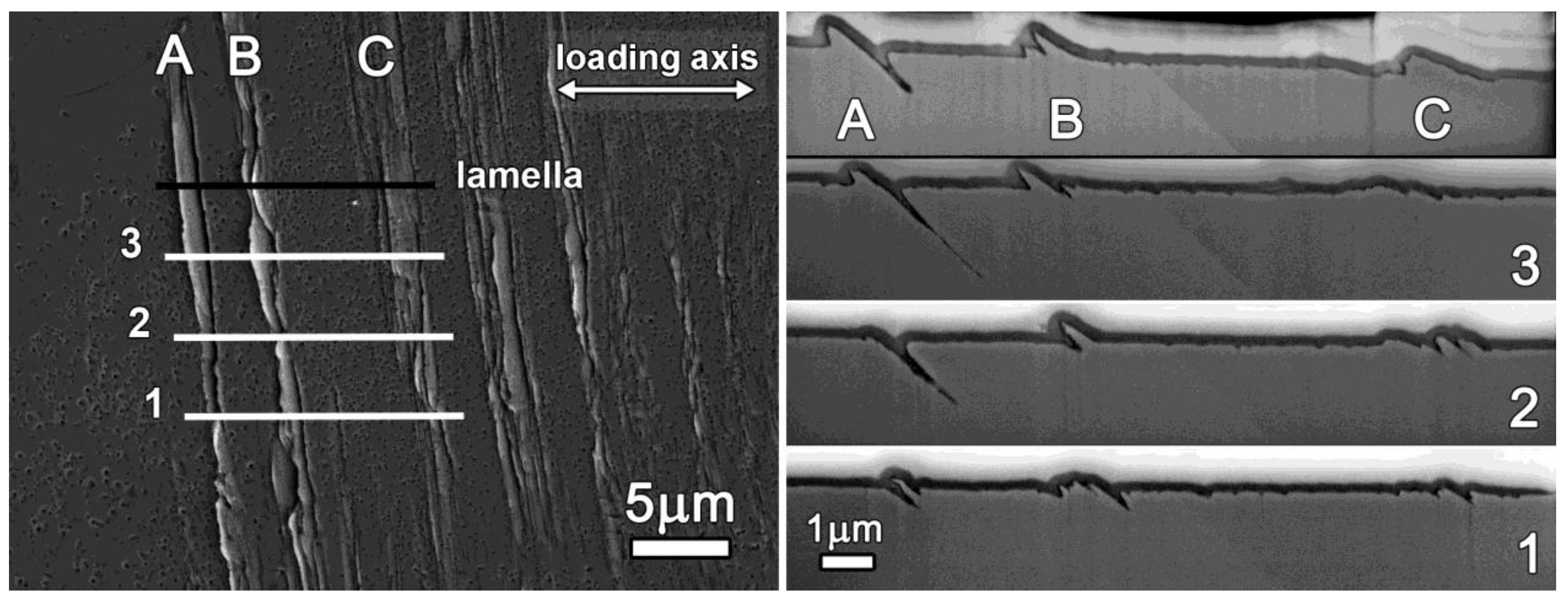
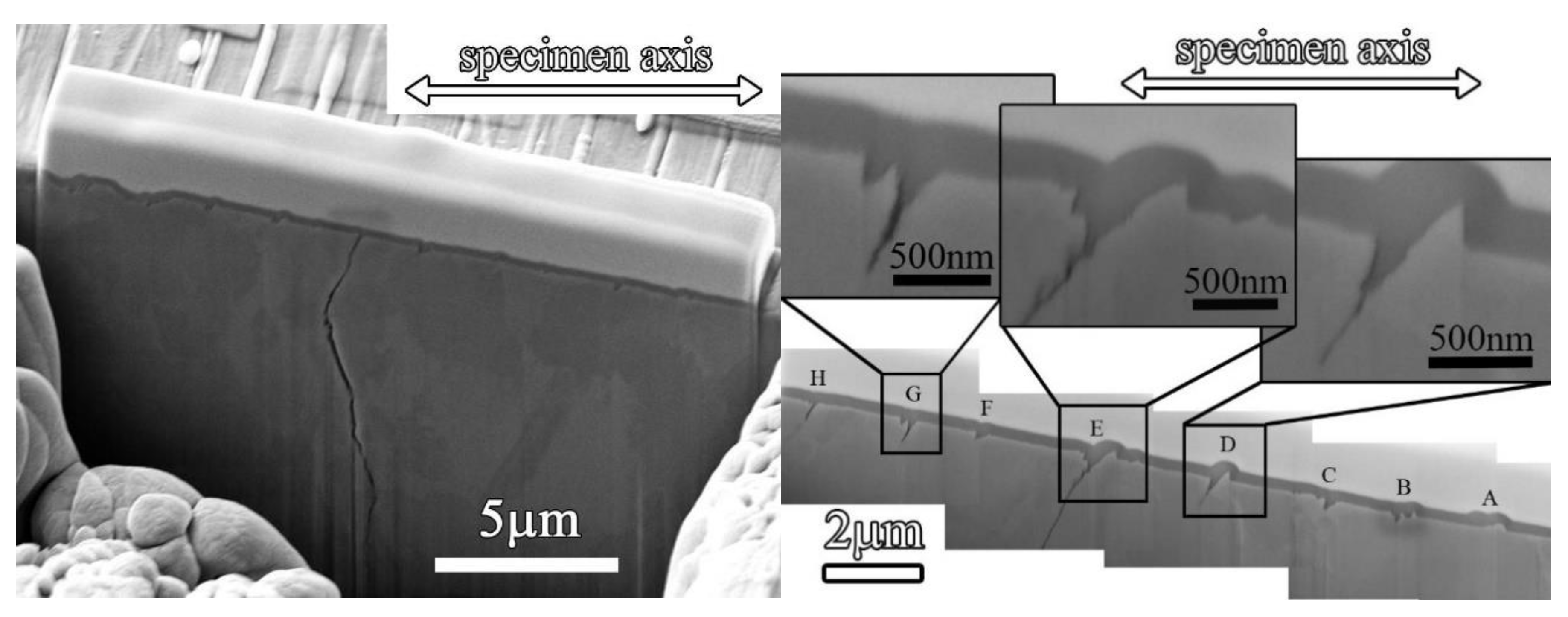
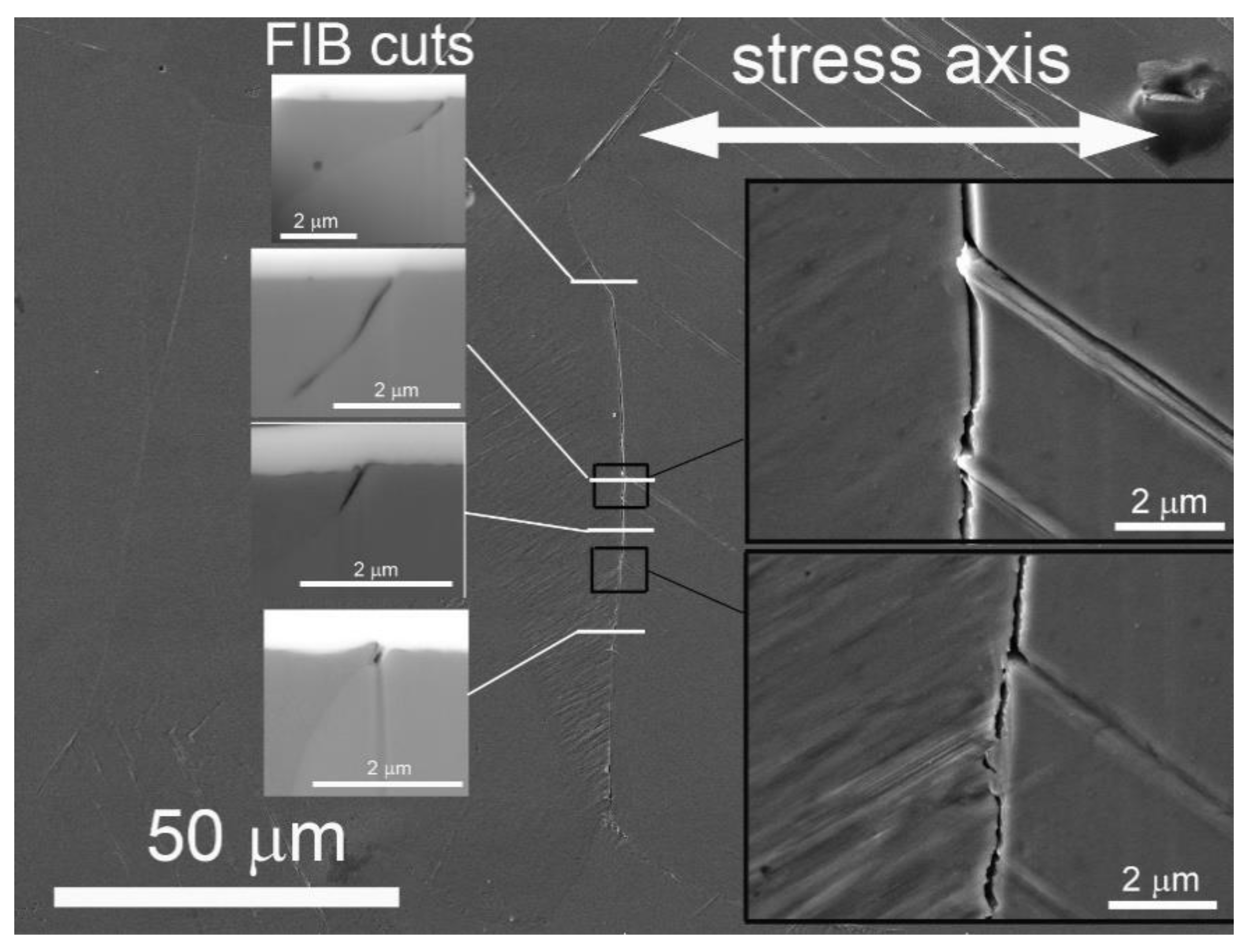
In order to assess the true shape of PSMs, focused ion beam (FIB) cutting was used and surface foils from the fatigued copper polycrystal [36] were prepared. Figure 4 (image to the left) shows the SEM image of the surface of the grain of the fatigued polycrystalline copper with PSMs A, B and C consisting of extrusions of variable height and parallel intrusions. Only the extrusions could be identified unequivocally on the SEM image of the surface. The FIB cuts of the grain in the locations shown on the SEM image, perpendicular to the surface, reveal the surface relief in four locations. The shape of the extrusions and the depth of the intrusions change along the length of the PSMs. The deepest intrusion is in cuts 2 and 3 at PSM A, and a short crack started from the tip of the intrusion in cut 3. In the location denoted “lamella”, not only the cut, but also a thin foil for TEM has been prepared (see later), which shows the shape and the height/depth of extrusions and intrusions, as well as the dislocation arrangement in the grain.
Numerous studies of the dislocation arrangement of PSBs in fatigued single and polycrystals have been performed, starting with the first observations of Laufer and Roberts on copper single crystals [14]. A ladder-like dislocation structure has been observed in polycrystalline copper [27] and other simple f.c.c. metals [41,42], austenitic steels [43] ferritic steels [44] and duplex steels [45]. Figure 5 shows the dislocation structure in the grains of austenitic and ferritic steels cycled to the end of the fatigue life. In austenitic steel (Figure 5a), the matrix has a random bundle structure but, in a direction parallel to the trace of the (111) primary slip plane, runs the PSB with a ladder-like dislocation structure. It is characterized by alternating dislocation-rich walls and dislocation-poor channels. A similar dislocation configuration is apparent in the ferritic grain (Figure 5b), where three well developed PSBs run parallel to the trace of the (01) primary slip plane.
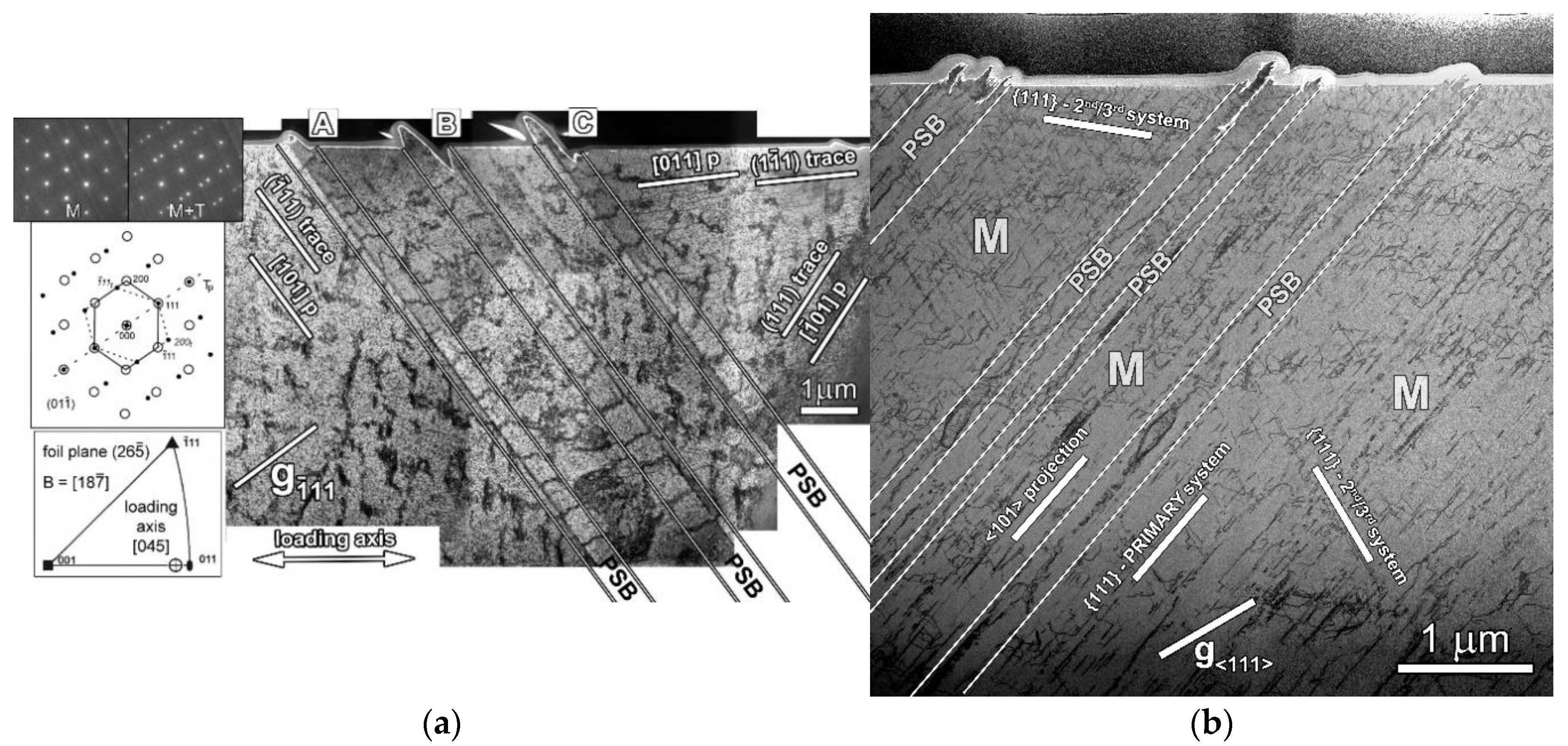
Recent studies involving the preparation of the foils from the surface [35,36] reveal both the surface relief and internal dislocation structure. Figure 6a shows three PSBs, in a grain of copper, parallel with the trace of the primary slip plane. They run along three twin boundaries and are characterized by a ladder-like dislocation arrangement. PSBs are embedded in the matrix structure, characterized by randomly arranged dislocation clumps. All three PSBs produced on the surface PSMs, consisting, in each case, of an extrusion and, in two of them, of a parallel intrusion. The volume of the extrusions is, in both cases, larger than the volume of the parallel intrusions. This is typical for the early stages of the fatigue life. In the initial stage of the fatigue life, only extrusions were detected (PSM A in Figure 6a); later intrusion appears on one or both sides of the intrusion. Several FIB cuts show that the height of the extrusions and the depth of the intrusions varies along the length of the PSM (see Figure 4). The shape of the extrusion in copper is hill-like. The intrusion is generally smaller than the extrusion and has a very sharp tip.
PSBs in superaustenitic stainless steel (Figure 6b) also run parallel to the primary slip plane (111), but their dislocation structure differs only moderately from the structure of the matrix. In the matrix, dislocations of all three active slip systems can be identified. Only in the areas that belong to the PSBs, dislocations from the secondary slip systems are missing. The removal of secondary dislocations from PSBs indicates high shear strain amplitude in the primary system of the PSB and, hence, high dislocation activity in PSBs. Areas of high dislocation density in PSBs (walls) alternate with areas of low dislocation density (channels). The PSMs in superaustenitic steel differ substantially from those in copper. They consist of thin, often irregular, extrusions and intrusions. This characteristic of PSMs is due to the low stacking fault energy of the material, in which dislocations are split into the partials and, thus, the slip is planar, and the cross slip is difficult.
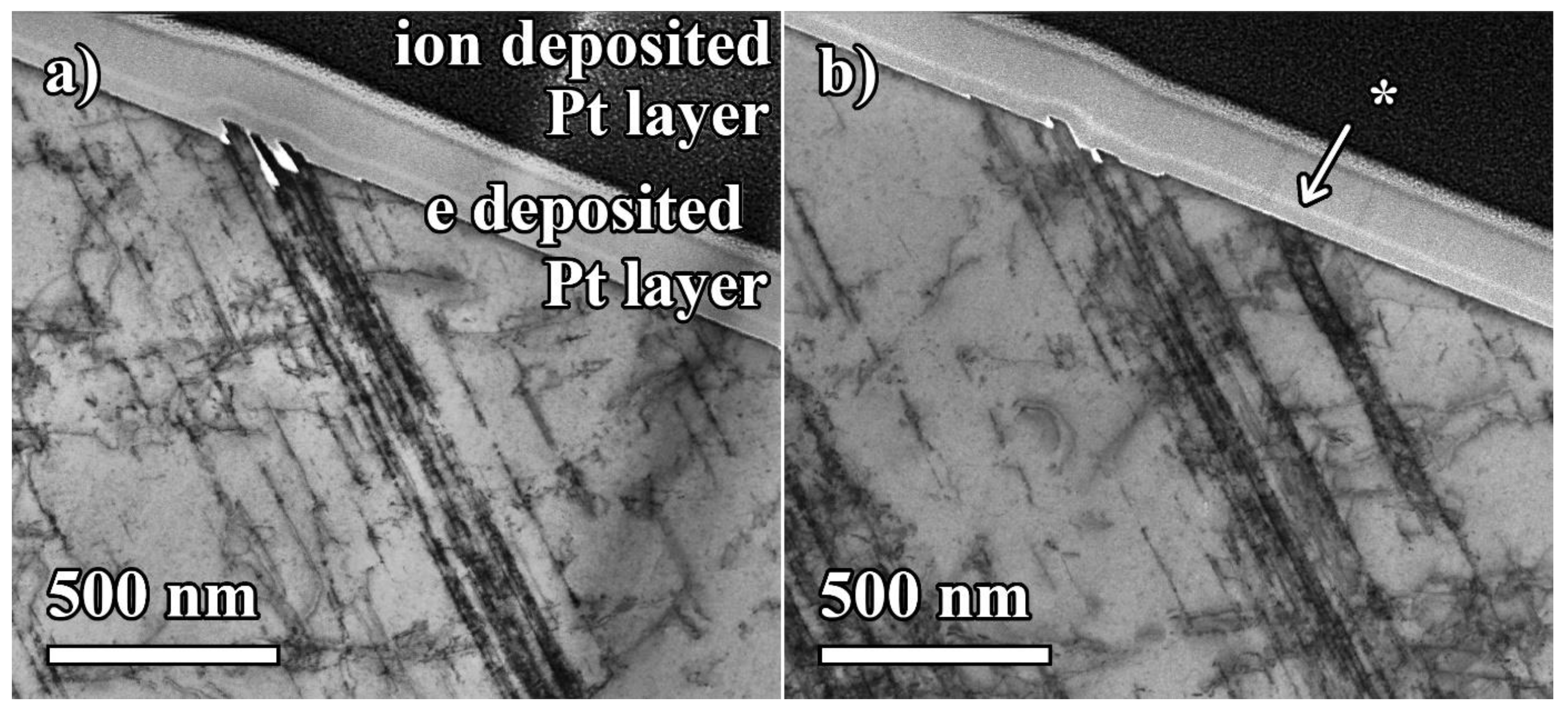
PSBs were also identified in the internal structure of fatigued superalloys [46,47]. The bands of intensive cyclic slip are characterized by a high dislocation density. Figure 7 shows the surface foil taken in a grain of RENE 41 superalloy in an annealed condition (dissolved precipitates), which was subjected to 30 cycles of high strain amplitude. The dislocation structure of the PSBs corresponds to the dislocation bands parallel to the primary slip plane. Areas of high dislocation density are often interrupted by areas with a low dislocation density. The cross slip is difficult, and the dislocations remain in their slip plane. The surface relief is formed by alternating thin extrusions and intrusions. Some slip bands did not produce any surface relief at this stage. Figure 8 shows the PSM and PSBs in the early stage of fatigued precipitation hardened superalloy RENE 41. The dislocation band cuts the precipitates; some of the precipitates are sheared. The dislocations in the band are distributed inhomogeneously, with some of them forming clumps.
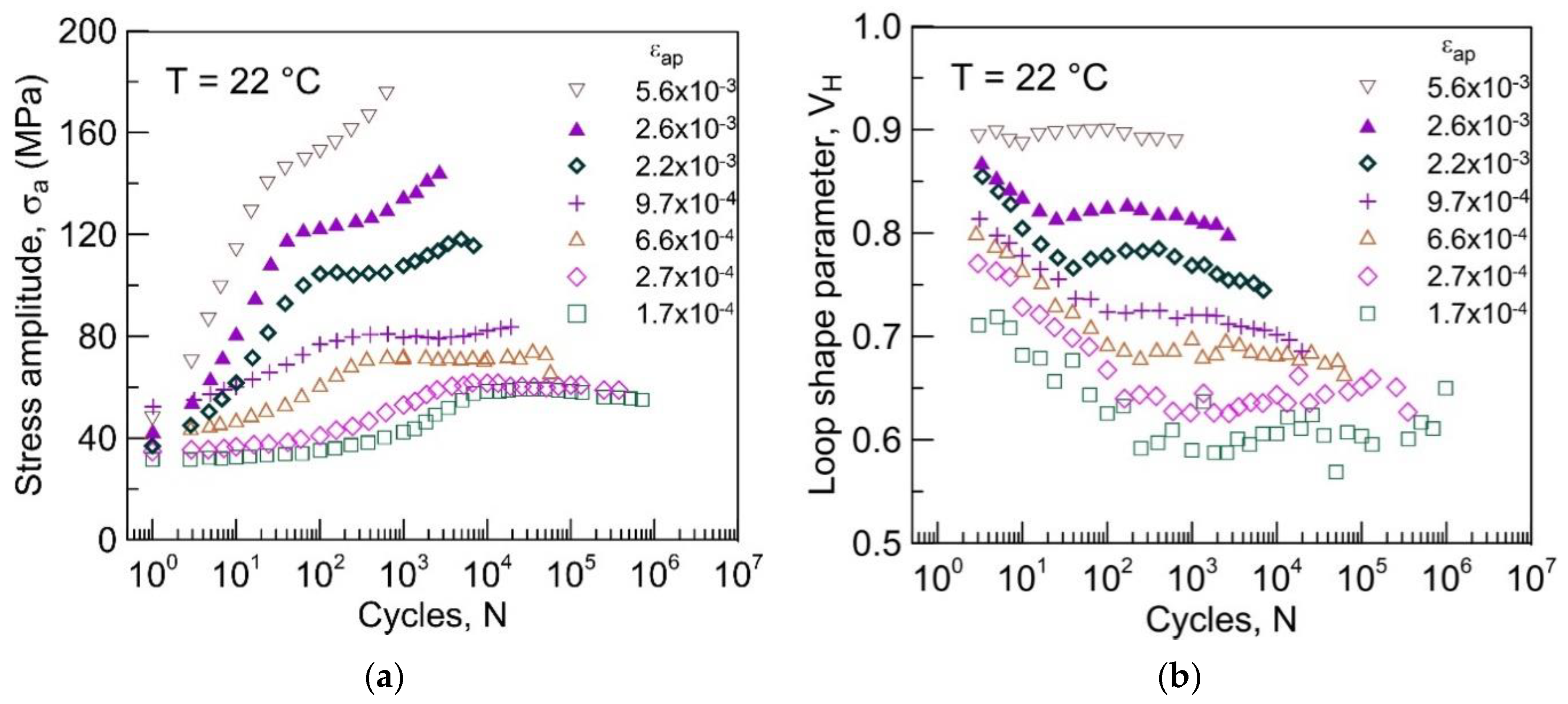
The localization of the cyclic strain can be detected by measuring the stress-strain response. Pronounced localization has been detected in copper single crystals [48,49], but it is also found in the polycrystals of simple metals and solid solution alloys. Figure 9 shows the plots of the stress amplitude (Figure 9a) and loop shape parameter (Figure 9b) vs. the number of cycles in constant plastic strain-controlled cycling. The loop shape parameter VH is the ratio of the hysteresis loop area, with respect to that of the circumscribed rectangle. It has been introduced by Mughrabi [48], who studied the stress-strain response of copper single crystal. The cyclic stress amplitude of polycrystalline copper increases in the initial stage of fatigue hardening, and later saturates or follows the secondary hardening stage (Figure 9a). The increase of stress amplitude is accompanied by the decrease in the loops’ shape parameter VH. VH reaches a minimum, and subsequently increases. The minimum of the VH corresponds to the start of cyclic strain localization. Due to the localization of the cyclic plastic strain into PSBs, the matrix is strained only elastically and, for low and medium applied plastic strain amplitudes, the stress amplitude saturates. Figure 9 shows that the localization of the cyclic strain begins before the stress amplitude saturates; namely, in the low strain amplitude domain.
2.2. Models of Cyclic Strain Localization
The early models of cyclic slip localization were based on the notion of individual dislocations producing extrusions and intrusions. Cottrell and Hull [18] consider two dislocation sources in different slip planes, corresponding to two highly stresses slip systems close to the surface. The alternate activation of these two sources can produce an extrusion-intrusion pair. Wood [50] proposed the card slip to create the extrusion-intrusion pair. Mott [51] considered the irreversible motion of screw dislocations to extrude material locally from the inside to the surface. Kennedy [52] modified the model and introduced the simultaneous motion of the edge dislocations and the formation of Lommer-Cottrell locks, which result in the irreversible motion of the screws with the cross slip. Watt [53] proposed the formation of extrusions through the interaction of the edge and screw dislocations, and the formation of unit dislocation dipoles through the non-conservative motion of the jogs on screw dislocations. All of these models, reviewed by Antolovich and Armstrong [20], were proposed before the relevant information concerning the surface relief and internal dislocation structures in fatigued metals was assessed.
The ladder-like dislocation structure observed in fatigued single and polycrystals (see Section 2.1) structure of alternating walls and channels, and the experimental study of the point defect production in cyclic straining [54], led to the first physically-based model of surface relief formation in cyclic straining. Essmann et al. [55] considered the interaction of dislocations in the structure of a PSB consisting of thin dislocation-rich walls and thick dislocation-poor channels. They concluded that a high plastic strain amplitude in PSB results in the production of point defects in PSB, preferably vacancies. Vacancies increase the volume of the PSB and the PSB lamella becomes elongated in the direction of the active slip vector. As a result, an extrusion is produced on the surface, where PSB emerge on the surface. The height of the static extrusion h is proportional to the saturated vacancy concentration cv,sat and to the depth D of a PSB in the direction of the primary Burges vector:
where Vv is the volume of the vacancy in the units of atomic volume. The profile of the static extrusion is roughened by the random slip [56].
h = Vvcv,satD.
The static extrusions [55,57] cannot explain the experimental observations of polycrystals. The height of the static extrusions, evaluated according to Equation (1), for the grain 50 μm, maximum vacancy concentration 5 × 10⁻⁴ and Vv = 0.8 is only 20 nm. The height of the extrusions observed in the experiments reaches 1 to 2 μm. Static extrusions stop growing as soon as the vacancy concentration saturates which, due to the high plastic strain amplitude in the band, happens early in the fatigue life. In reality, most extrusions grow until the end of the fatigue life. Moreover, static extrusions can arise only at temperatures at which vacancies are immobile as mobile vacancies migrate and disappear at dislocations. The model does not predict intrusions.
The analysis of the geometry of extrusions and intrusions, the relation of the internal dislocation structure and the surface relief, the modeling of the interaction of dislocations leading to the formation of point defect and their migration to sinks, led Polák [58] to propose a new model of a surface relief formation producing extrusions and intrusions. It is based on the continuous interaction of dislocations in the channels, the formation of vacancies in the PSB and their migration to the matrix, where they are annihilated at edge dislocations. This process leads to the steady growth of extrusions and the formation and growth of parallel intrusions, which agrees with multiple experimental observations (see Section 2.1). Polák’s model was a starting point for the quantitative description of the growth of extrusions, provided the PSB/matrix boundary represents an infinitive sink [59], and also to the general solution of the production of extrusion and intrusion pairs if vacancies produced in PSB migrate to the matrix and are annihilated at dislocations [60].
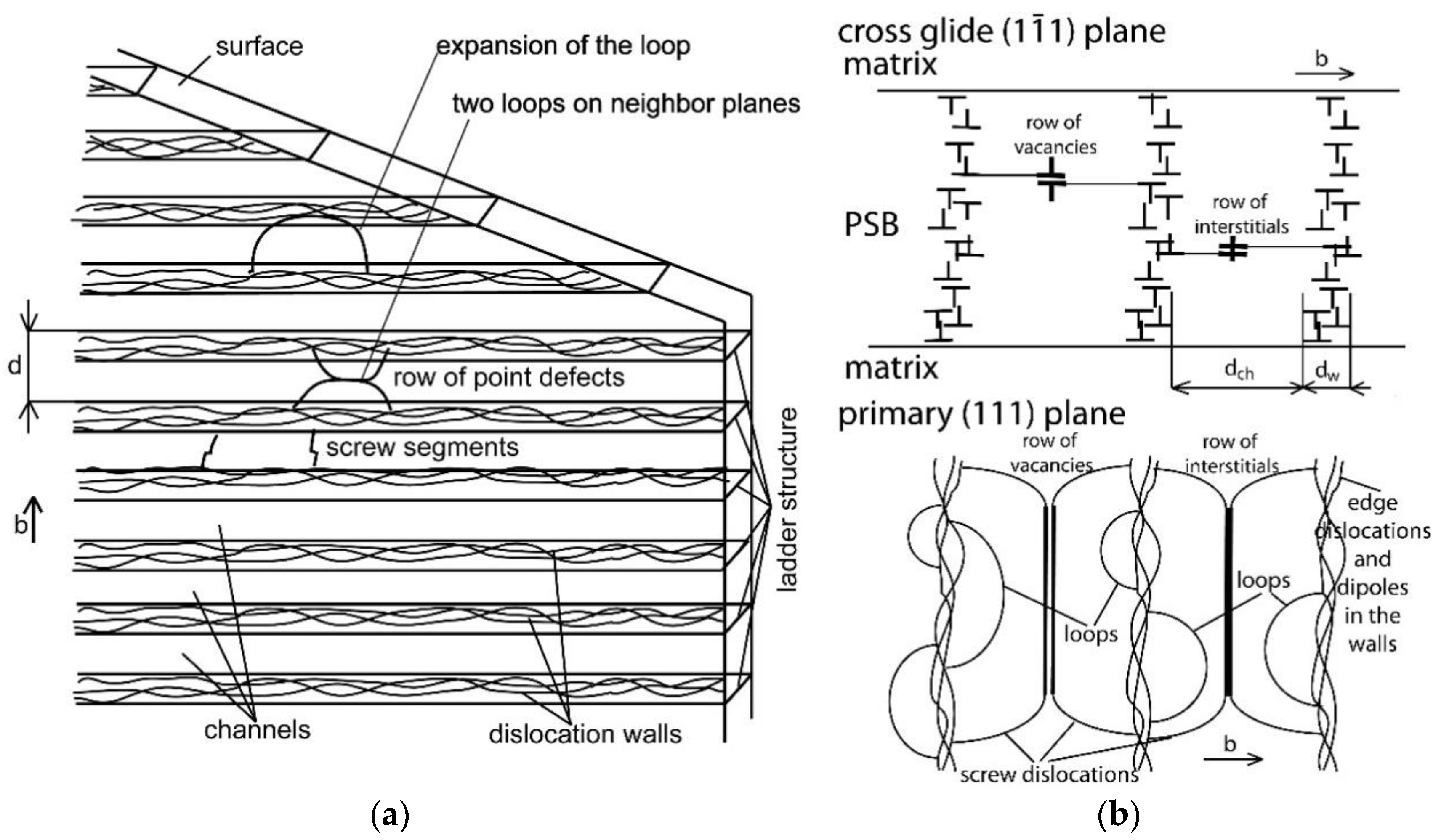
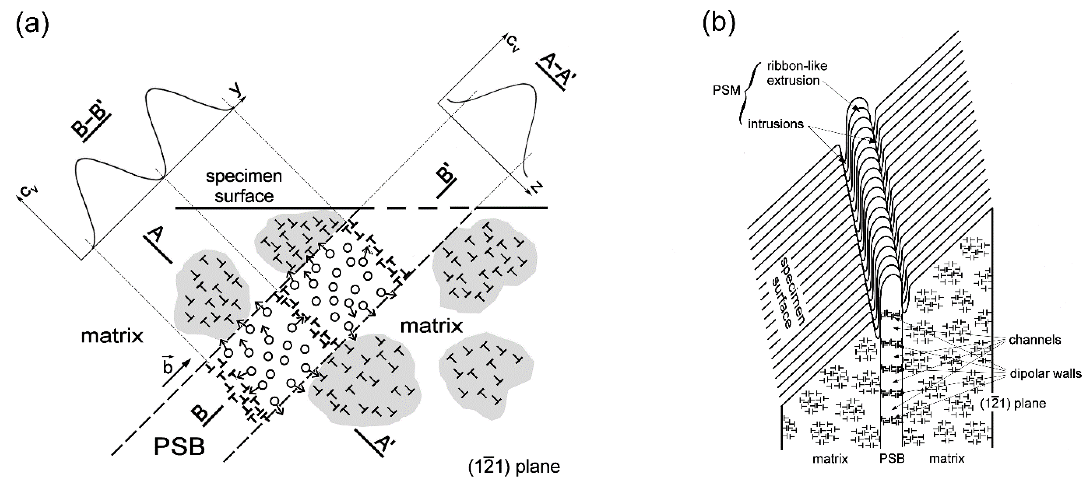
The general solution is based on the ladder-like arrangement of dislocations in the PSB, consisting of alternating dislocation-rich walls and dislocation-poor channels. This arrangement is schematically shown in Figure 10a. In cyclic straining, dislocation loops are emitted from the walls on both sides and mostly arrive to the neighbor wall. The dislocation loop running in the adjacent slip planes, in opposite directions, can meet in the channel. The edge segments annihilate and row of point defects are produced (Figure 10b). Two screw segments are left with nonconservative jogs. Under the applied stress, the jogs move apart, thus producing vacancies or interstitials. Due to the vacancy formation energy being lower than the interstitial formation energy, vacancies are predominantly produced.
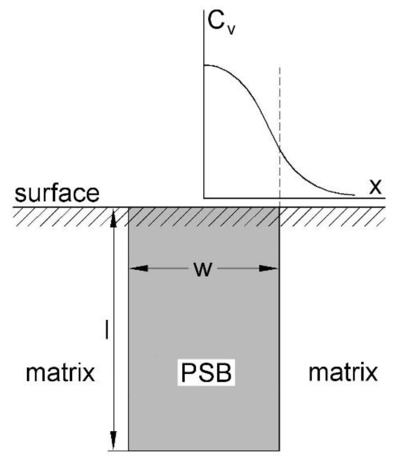
During cyclic straining, vacancies, steadily produced in the channels, migrate to the edge dislocations within the PSB, i.e., in the walls, and also out of the PSB in the matrix. This is schematically imaged in Figure 11a, with the concentration profile of vacancy concentration -cv- in two directions. In a simplified picture, we suppose that vacancies are steadily produced in the whole volume of the PSB with the production rate p (increase in the vacancy concentration in a cycle). The fraction A of these vacancies within the cycle, whose period is τ, is athermally annihilated by sweeping dislocations. If vacancies are mobile with diffusion coefficient Dv, they simultaneously migrate to the matrix and are annihilated at the edge dislocations in the matrix. Edge dislocations in the matrix are randomly distributed with the density ρe.
Figure 12 schematically shows the PSB and the profile of the vacancy concentration within PSB and in the matrix. The profile can be evaluated by solving the diffusion equation in a steady state:
and
with appropriate boundary conditions.
The solution of these equations yields a vacancy profile and, from this profile, the height of the extrusion hE and the depth of intrusion dI (see [60] for the details) vs. the number of cycles can be found.
where a = is the reciprocal characteristic diffusion distance, which considers the athermal vacancy annihilation, and
is the characteristic length, which depends on the difference between the cyclic yield stress of the matrix and that of the PSB. Parameter dc determines the lag in the number of cycles between the start of the formation of the extrusion and the two intrusions.
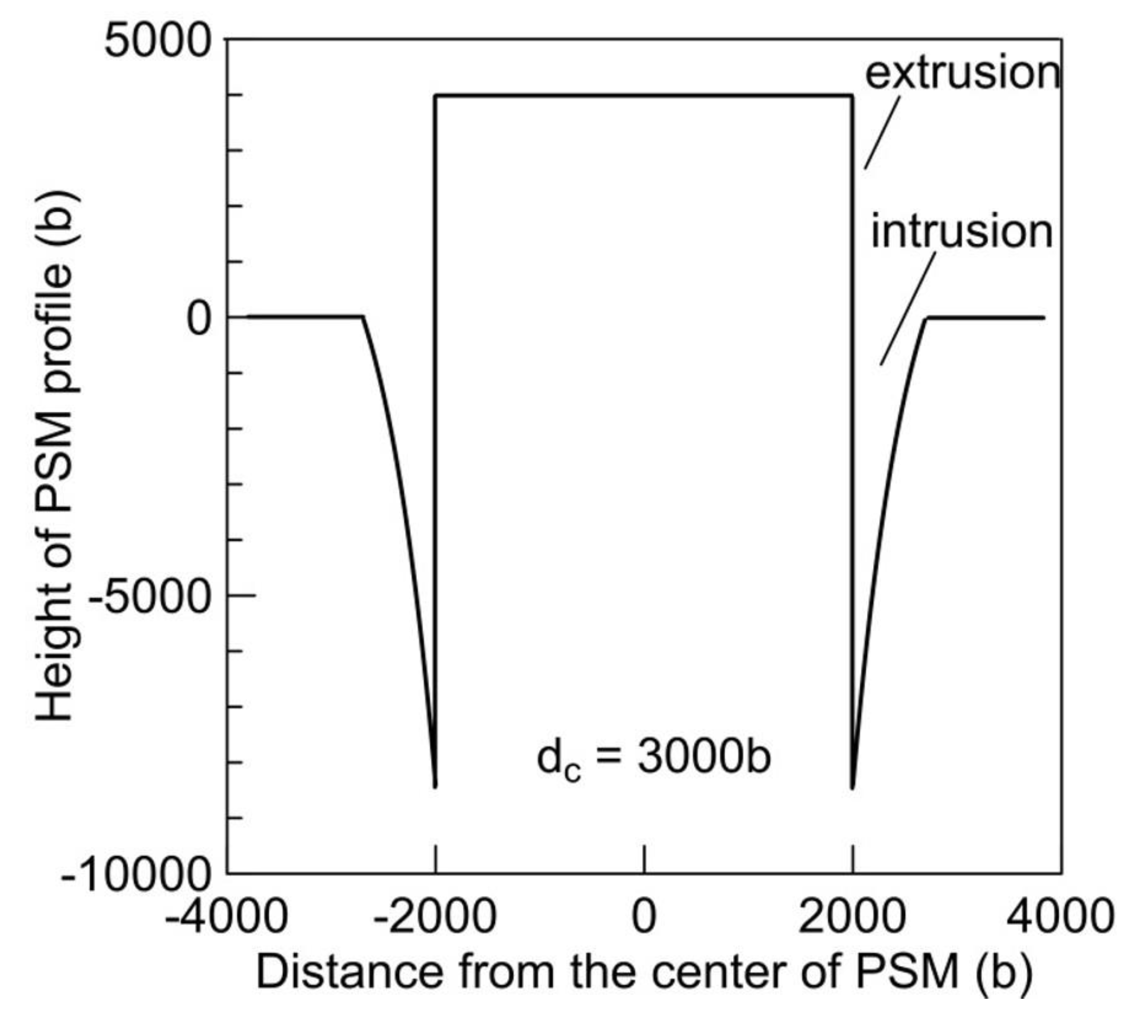
Figure 13 shows the profile of PSM calculated using relations (4) and (5) consisting of central extrusion and two parallel intrusions. Parameters used correspond to polycrystalline copper.
The calculation of the PSM profile predicts the important features of the extrusions and intrusions:
- (1)
- PSMs start as extrusions, and intrusions develop later. This is due to the lower yield stress of the PSBs than that of the matrix.
- (2)
- The volume occupied by intrusions is smaller than that occupied by extrusions.
- (3)
- A very sharp shape of intrusions is predicted.
All of these features were observed experimentally (see Section 2.1).
The quantitative model of PSM formation has been developed, assuming the ladder-like dislocation structure of the PSB. However, the model corresponds to any dislocation structure of a PSB in which dislocation-rich volumes alternate with dislocation-poor volumes. In this case, vacancies are produced in dislocation-poor volumes and migrate to the matrix, where they are annihilated. The shape of the PSM in a particular location on the surface thus depends on some average of the dislocation distribution below the surface, in the direction of the Burgers vector. Therefore, extrusions often have the shape of a ribbon, with variable height, and intrusions have the shape of a sharp trench whose depths also varies along its length. This is often the case in copper or austenitic steel (see Figure 3 and Figure 4).
3. Fatigue Crack Initiation in Slip Bands
The first experiments to document the initiation of fatigue cracks from slip bands using an optical microscope were performed by Ewing and Humfrey [11]. When PSBs were identified in fatigued metals, Tanaka and Mura [61] proposed a micromechanical crack initiation model in which PSB is modelled as a plate-like distribution of dislocation vacancy-type dipoles. The accumulation of dipoles during cycling increases the internal tensile stress. The crack initiates suddenly when the fracture criterion is satisfied, i.e., when the repulsive stress between the dislocations piled up on the closely spaced planes exceeds a critical value. The number of cycles to crack initiation, Ni, is given by:
where G is the bulk shear modulus, Ws is the specific fracture energy, Δτ is the resolved shear stress range, τi is the frictional shear stress, ν is the Poisson’s ratio, and d is the grain diameter. Their equation is often used and has been modified by a number of authors [62,63]. The subject of fatigue crack initiation based on the micromechanical approach has been reviewed by Sangid [9] without pointing to the role of intrusions.
Experimental studies in copper polycrystals [35], superaustenitic steel [35,36,64] and 316L steel [65] revealed the principal mechanism of fatigue crack initiation in slip bands: crack-like intrusions produce fatigue cracks. Figure 14 shows a FIB cut of a grain boundary of fatigued 316L steel with parallel PSMs on the surface. Part of the surface was covered by two sheets of platinum. One macroscopic deep crack runs approximately perpendicular to the stress axis. The detailed image to the right reveals the details close to the surface. With the exception of PSM A, which consists of extrusions, all of the other PSMs also have intrusions. From the intrusions of PSMs D and E, a fatigue crack started. The growth rate of crack E was evidently larger than that of crack D; therefore, this crack became a macroscopic crack and crack D stopped growing, reaching the depth of about 500 nm, approximately the same as the depth of the intrusion from which it started.
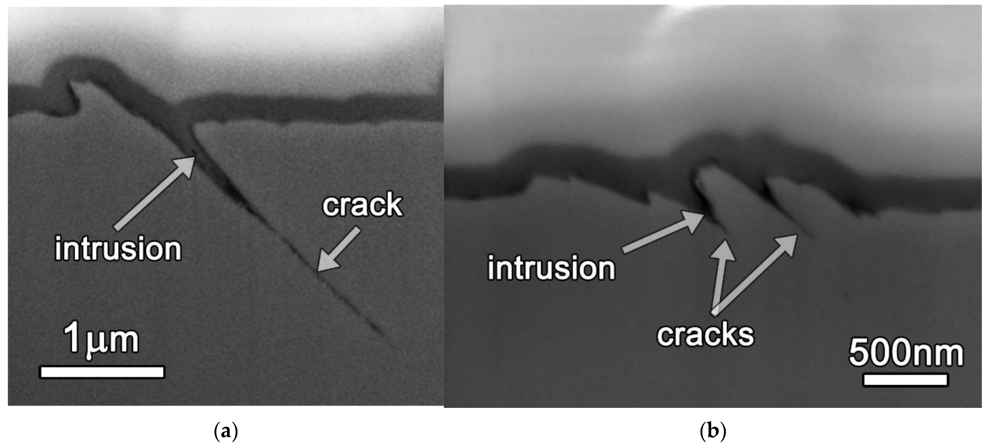
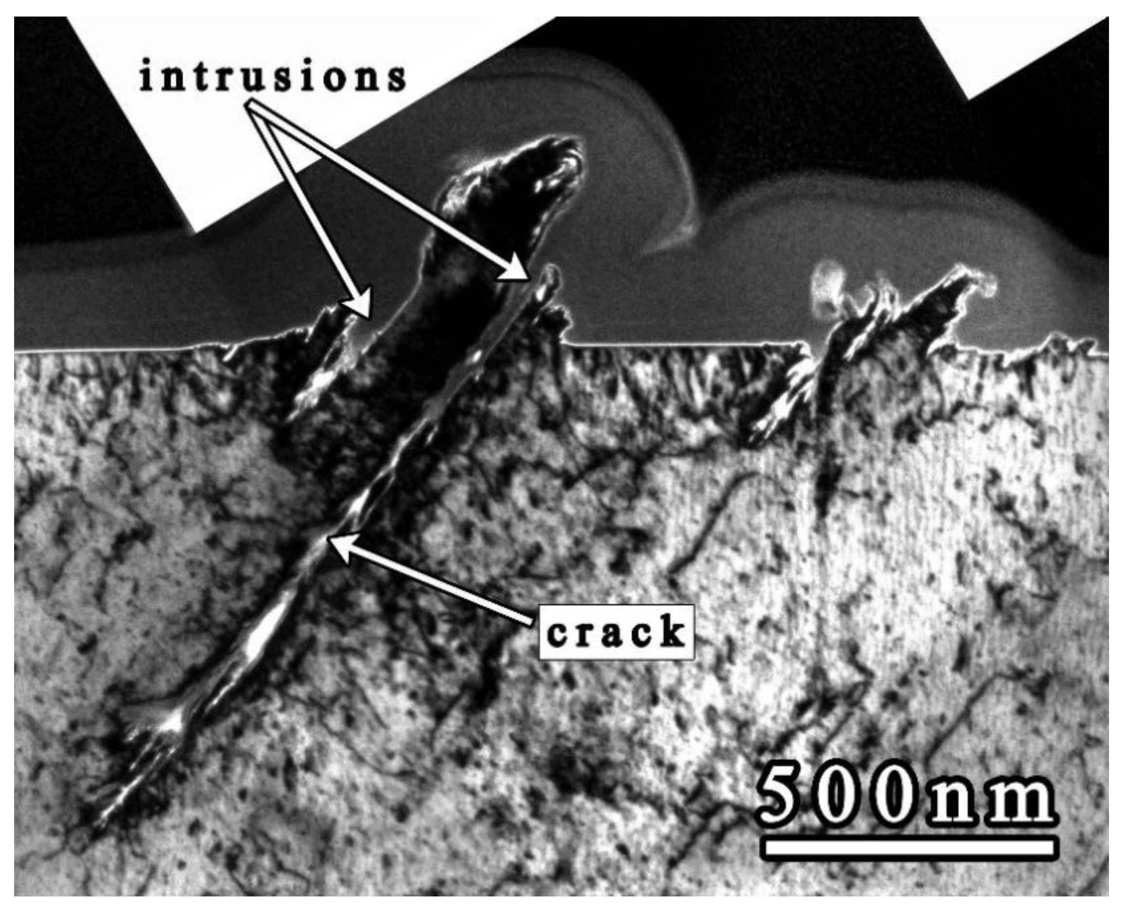
Another example of fatigue crack initiation can be observed on the FIB cuts of Sanicro 25 steel, shown in Figure 15. A typical PSM, consisting of extrusions and parallel intrusions, produced a crack of a length about 1.5 μm, starting from the tip of an intrusion (Figure 15a). It runs under about 45 degrees, which corresponds to the trace of the primary slip plane. Two starting cracks can be recognized in the tip of two intrusions in Figure 15b. Starting fatigue cracks were also identified on the lamella observed in TEM. Figure 16 shows two cracks starting from the intrusions of two PSMs in a grain of fatigued Sanicro 25 steel. The initiation and early growth always follow the primary slip plane.
Slip band fatigue crack initiation is enhanced at the twin boundaries, and the twin boundaries thus serve as preferential sites for crack initiation. Twin boundaries contribute to higher cyclic strain localization due to incompatibility stresses at a twin boundary [66,67,68,69,70,71,72,73,74]. Neumann and Tönnessen [67] found that the fatigue crack was preferentially nucleated in every second twin boundary due to additional stresses. The source of these additional stresses acting in coherent twin boundaries under cyclic straining has been analyzed by Heinz and Neumann [68]. Neumann [69] obtained an analytical solution for the incompatibility stresses at twin boundaries in cubic crystals. He concluded that the observed slip activity and crack initiation at the surface is due to an additional logarithmic stress singularity. That is, elastic twin anisotropy shear stress, τSF, which is added to the shear stress, resulting from the external load, which in turn results in a higher local strain amplitude and the early formation of a PSB close to the twin boundary. PSM develops and a crack starts from the intrusion. Stinville et al. [71,72] and Prouteau et al. [74] studied the crack initiation sites in a twin boundary in a polycrystalline nickel-base superalloy and in titanium alloys. Heczko et al. [73] observed cyclic strain localization and the formation of PSMs around thin deformation microtwins in a high entropy alloy.
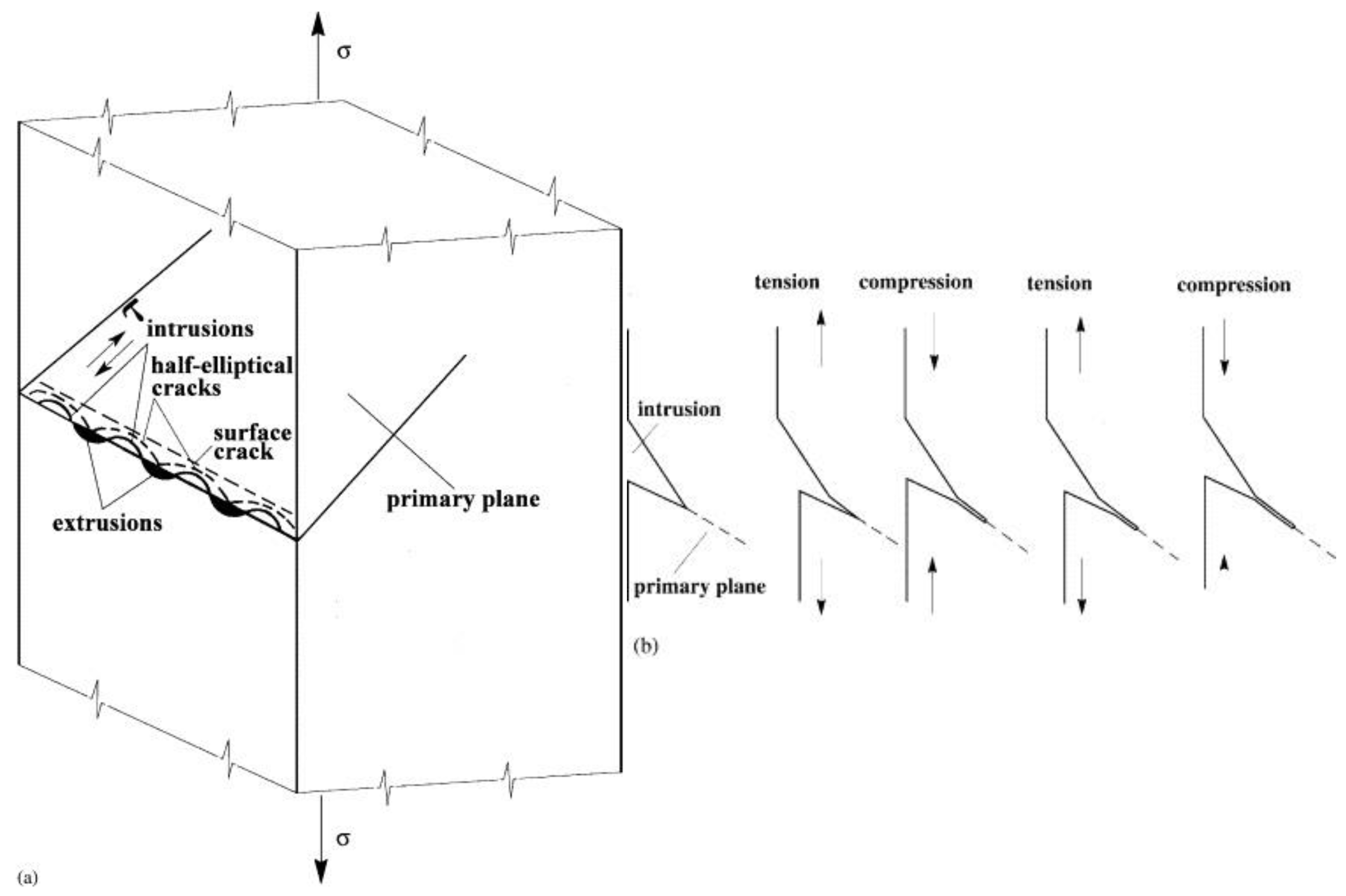
The high stress concentration in the tip of an intrusion produces the local slip–unslip mechanism on the primary slip plane. The irreversible slip–unslip mechanism, as a mechanism of fatigue crack initiation, was originally considered by Wood [75]. A more specific model, which considers the line of alternating intrusions and extrusions at the emerging PSBs, has been proposed by Polák and Liškutín [76]. Two mechanisms for the initiation of the fatigue crack were considered and are schematically shown in Figure 17. It is expected that several intrusions (alternating with extrusions) are produced in the line of PSM, as found in experiments with copper [22]. From these intrusions, semi-elliptic cracks can initiate and become linked, creating a shallow surface crack. Figure 17a schematically shows the environmentally assisted nucleation of such a surface crack from a row of semi-elliptic intrusions/cracks. The material between the neighboring semi-elliptic intrusions/cracks, as depicted in Figure 17a, is subjected to antiplane shear deformation. This leads to the formation of new surfaces; the growing half-elliptic cracks link and, eventually, a shallow surface crack is formed along the whole length of the PSM. The crack can also arise from a single large intrusion. Figure 17b illustrates the environmentally affected slip-unslip mechanism of the production of a short crack from the tip of the intrusion. The slip step in the tension produces a new surface and, due to the corrosion [77], the complete rewelding in the compression phase of the cycle is prevented and the crack advances in the primary slip plane. The crack growth rate depends on the shear strain amplitude and on the aggressiveness of the environment. The same mechanism applies to antiplane shear deformation, and results in the joining of the semi-elliptic cracks and the formation of a surface crack.
4. Grain Boundary Fatigue Crack Initiation
Grain boundaries in polycrystals represent a two-dimensional defect, which affects their mechanical behavior. A fatigue crack may initiate intergranularly during cyclic loading. Low angle grain boundaries (LAGBs) only have a minor effect on crack initiation as dislocations can easily pass from one grain to the neighbor grain, and no grain boundary damage develops. High angle grain boundaries (HAGBs) are often the location of crack initiation. Kim and Laird [78,79] studied crack initiation in polycrystalline copper. Using interferometric observations, they found that cyclic loading produced large steps at the grain boundaries. They concluded that the stress concentration developed at these steps is the source of grain boundary fatigue crack initiation. Figueroa and Laird [80] cycled polycrystalline copper with a large grain size (~400 μm) and, using a plastic replica, they monitored the evolution of the surface in constant amplitude loading, in low-high tests and in high-low tests. They found that the initiation of cracks is directly related to the localization of the plastic deformation. In the high amplitude region, the intergranular crack initiation was directly related to the degree of slip activity in the neighbor grains. In the low amplitude region, the fatigue cracks were initiated due to PSBs by the impingement mechanism. Liang and Laird [81,82,83] investigated the effect of grain size on the type of fatigue crack initiation in polycrystalline copper. They found that intergranular initiation is preferred in coarse-grained material, while, for fine grained material, fatigue cracks largely initiated intragranularly from PSMs.
The mechanism of the grain boundary crack initiation in cyclic loading was suggested by Tanaka and Mura [61]. The embryo of the grain boundary crack could be initiated by the stacked pile-ups of vacancy dipoles oriented to the grain boundary, creating high local stress. A similar approach was adopted by Mughrabi et al. [84,85]. Based on the model of extrusions in crystals [55], they proposed that static extrusions in the grain produce superdislocations in the PSB/matrix interface and these pile-up against the grain boundary. The stress concentration can cause the initiation of “brittle-type” PSB-GB cracks. Christ [86,87] proposed an expression for the critical stress that can induce the grain boundary cracking due to the pile-up of the interface dislocations related to the saturated concentration of static vacancies in the PSBs
where γ is the surface energy, d is the grain size, and f(α,β) is the function of the angles; α is the angle between the stress axis and the trace of PSB on the surface, and β is the angle between the trace of the PSB on the surface and the trace of the grain boundary plane.
The idea of dislocation pile-ups and the brittle fracture appearance of incipient cracks due to high local stress was followed in a number of theoretical and experimental papers. Liu et al. [88] performed an analysis of the stresses exerted by the dislocation pile-ups in PSBs and derived the relationship to be similar to relation (8) for the stress necessary to initiate a PSB-GB crack. Burmeister and Richter [89] analyzed the approach of Liu et al. and derived the critical stress for brittle crack appearance on the grain boundary. The thorough analysis of the stress field at the grain boundary due to the slip band impingement was performed by Sauzay and Moussa [90] and Sauzay and Vor [91]. The competition between dislocation transmission and dislocation source activation on the grain boundary was recently investigated by Liu et al. [92]. Systematic studies of the fatigue cracking mechanisms in the grain boundaries in bicrystals and polycrystals were performed by Zhang, Yang, et al. [93,94,95,96,97,98,99,100]. They demonstrated that lattice dislocations tend to pile up with the impingement of coplanar slip bands at the HAGB due to the large difference between the slip vectors on both sides of the grain boundary. A high stress concentration could largely facilitate the intergranular fatigue cracking.
All of these studies aim to evaluate the stress acting on the grain boundary, either from the simple pile-up of dislocations acting on one plane or by considering the thickness of the slip bands. In those studies, the microcracks at the grain boundary result from brittle-type cracking caused by high local stress. The local plastic effect of the PSBs consisting of the formation and the growth of extrusions and intrusions on the grain boundary has not been considered. The effect of the extrusions and intrusions emanating from neighboring grains on the grain boundary was recently studied in polycrystalline copper [101] and in Sanicro25 austenitic steel [102]. Grain boundary cracks, produced in high and low strain amplitude straining, were studied in copper and, based on the results of Sanicro 25 steel [102], a new mechanism of grain boundary cracking has been proposed.
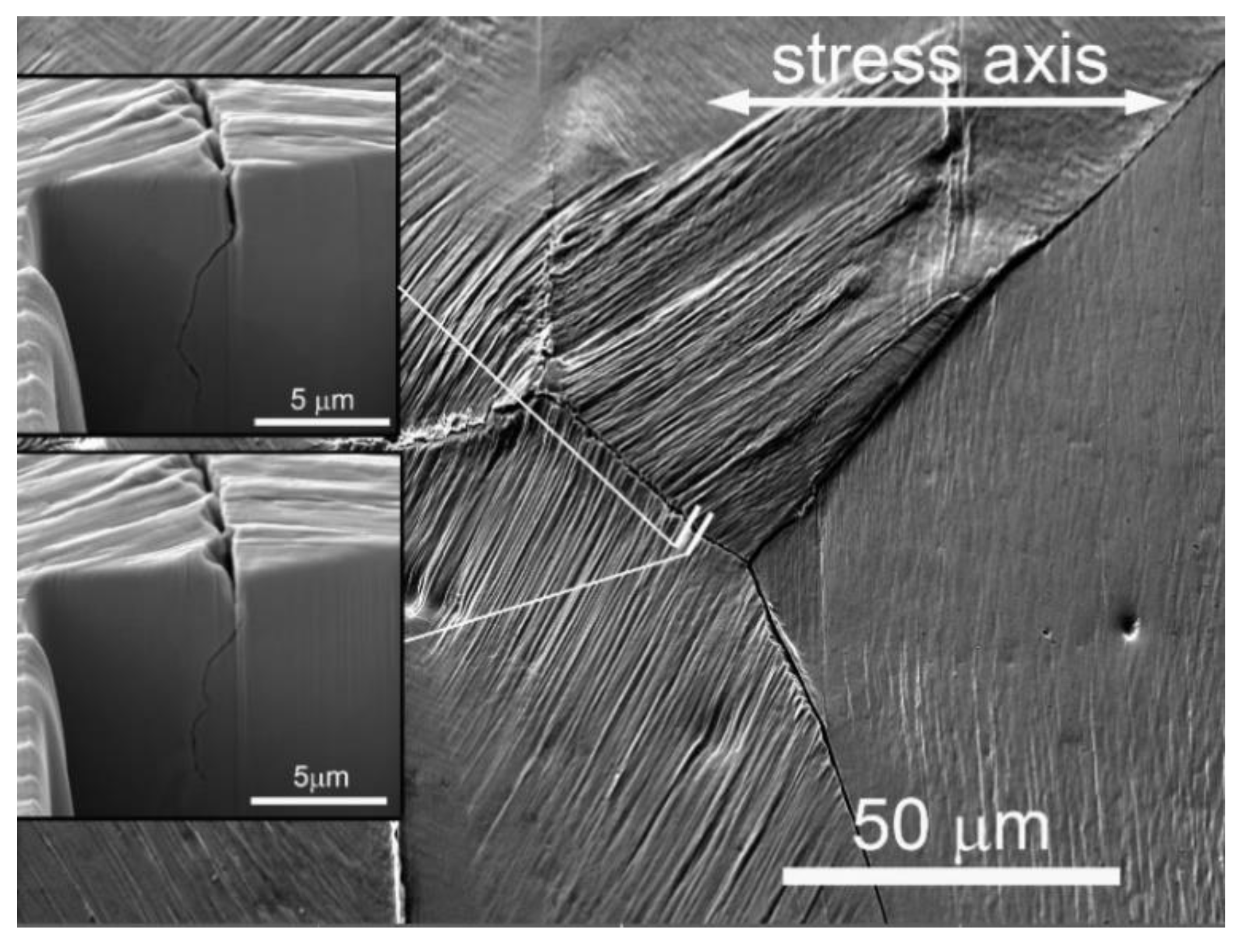
Figure 18 shows the surface of copper after cycling with a high strain amplitude (εH) to the end of the fatigue life. Both the neighboring grains have distinctive slip markings developed on their surface. Cyclic slip cannot continue from one grain to the other grain. The grain boundary is cracked, and the crack is open. The cracked boundary is perpendicular to the stress axis. The PSBs in both of the neighboring grains are at the surface, inclined at approximately 45 degrees to the grain boundary. Two details of the grain boundary crack are shown as insets. The PSMs that developed on the surface of both grains consist of alternating parallel extrusions and intrusions. However, extrusions and intrusions emanated not only on the grain surface, but also on the grain boundary. They can be clearly identified on the cracked grain boundary in both insets. The extrusions on the grain surface correspond to the local intrusions on the grain boundary and, vice versa, the intrusions on the surface correspond to the extrusions on the grain boundary. These intrusions, simultaneously with their neighbor extrusions on the grain boundary, are the source of the grain boundary cracking.
The surface of copper at the early stage of the damage of the grain boundary (10% of fatigue life) is shown in Figure 19. Here, mild surface intrusions are accompanied by grain boundary intrusions and surface extrusions by grain boundary extrusions. At high resolution, the crack embryos can be distinguished in the locations of the grain boundary intrusions. Grain boundary intrusions introduce discontinuities and grain boundary extrusions push two grains apart, thus opening the crack. The grain boundary crack arises close to the surface, as documented in Figure 20. A surface grain boundary crack grows in the bulk of the material. Close below the surface (around 3 μm in Figure 20), a crack running in the slip plane started from the grain boundary crack.
The initiation of grain boundary cracks in cycling with a low strain amplitude (εL = 4 × 10⁻³) is illustrated Figure 21 and Figure 22. The surface of copper is shown at the early stage of cyclic loading (4% of fatigue life). In Figure 21, a low density of PSMs in the right grain produces grain boundary extrusions. In addition to these pronounced PSMs, the fine slip from the left grain contributes to the grain boundary damage. A short grain boundary crack is produced, as shown by the FIB cuts in the insets. The role of the fine slip, in addition to the intrusions and extrusions, is shown in Figure 21. The slip on the surface is very fine, but the relief on the grain boundary is sufficiently rough to produce a grain boundary crack. Figure 22 documents the role of fine slip in the evolution of the grain boundary fatigue damage during cycling with low strain amplitudes [101].
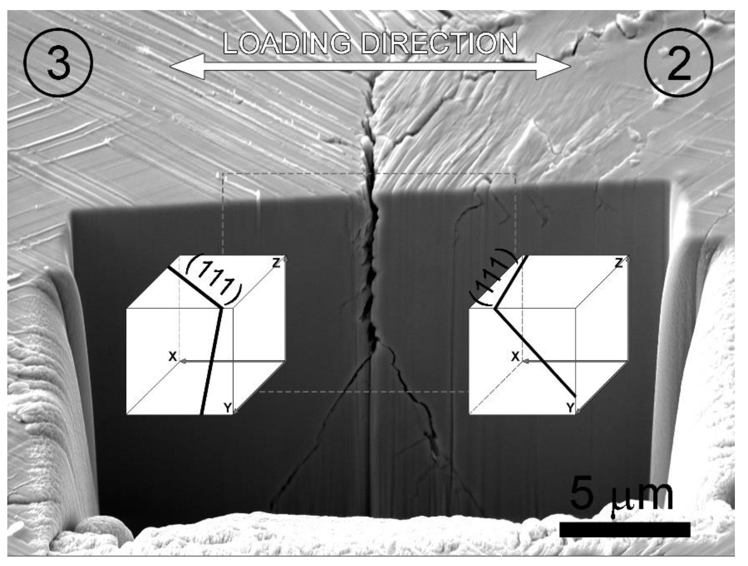
The identical mechanism of grain boundary initiation was observed in fatigued Sanicro 25 stainless steel by Mazánová et al. [102]. Figure 23 shows the surface and the FIB cut of two neighbor grains with a short grain boundary crack. The PSBs that run in both grains in the {111} planes and at the grain boundary produce rough relief, resulting in the formation of a grain boundary crack. Grain boundary extrusions and intrusions produce damage in the grain boundary. The crack has the depth of only around 5 μm and, from the tip of the grain boundary crack, two cracks running in the {111} planes have arisen.
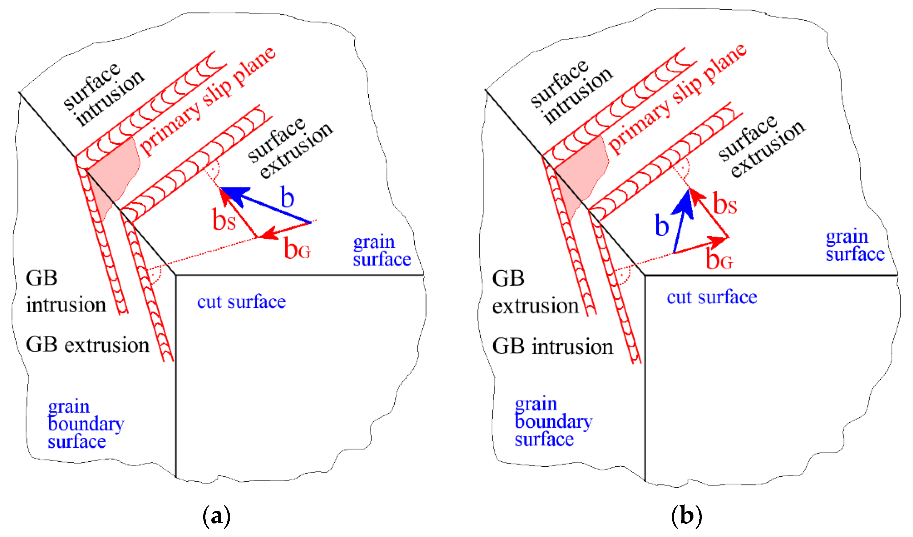
The experimental evidence reveals the essential role of PSBs and PSMs in the initiation of the intergranular crack. It was found that intrusions and extrusions arise not only on the surface of the grains, but, typically, also at the grain boundary. The analysis of the images of starting and well-developed grain boundary cracks revealed two types of relationships between the surface extrusions and intrusions, and the grain boundary extrusions and intrusions. Figure 24 schematically shows the images of two grains with the surface at the top, the grain boundary on the left and the normal cut in the front. Two PSBs run parallel to the primary slip plane, one producing a surface extrusion, the other a surface intrusion, which are identical in both images. Provided the normal component of the primary Burgers vector in the slip plane is oriented in the direction towards the grain boundary (Figure 24a), the PSB lamella producing the surface extrusion also produces an extrusion on the grain boundary. The lamella producing surface intrusion also produces a grain boundary intrusion. This case corresponds to the detail of the grain boundary crack showing grain boundary extrusions and intrusions in Figure 19 and Figure 21. Provided the normal component of the primary Burgers vector is oriented in the direction away from the grain boundary (Figure 24b), the PSB lamella producing surface extrusion produces a grain boundary intrusion. The PSB lamella producing surface intrusion produces a grain boundary extrusion. This case corresponds to the detail of the grain boundary crack shown in Figure 18 and Figure 22.
The experimental data on intergranular fatigue crack initiation demonstrate similar mechanisms active in both high and low amplitude cyclic straining. The necessary condition for the initiation of an intergranular crack is a suitable orientation of at least one neighbor grain that can produce PSMs impinging on the grain boundary. Extrusions and intrusions emerging on the grain boundary induce grain boundary cracking. At low amplitudes, the very fine slip, parallel to the PSMs, contributes to the grain boundary damage by producing nano-extrusions and nano-intrusions on the surface as well as on the grain boundary. With the decreasing strain amplitude, the density and the height of PSMs decreases, resulting in a lower degree of grain boundary damage. The height of the extrusions and intrusions on the grain boundary depends on the orientation of the Burgers vector, with respect to the grain boundary (see Figure 24), and on the grain size. Large grains produce more intensive grain boundary damage and rapid grain boundary crack initiation.
5. Summary
Cyclic slip localization and the formation of PSBs and PSMs in the cyclic straining of polycrystalline materials play an extremely important role in the evolution of fatigue damage and, in particular, in the initiation of fatigue cracks. The specific dislocation structure, consisting of alternating volumes of high and low dislocation density, arises in the bands parallel to the primary slip plane in individual grains. This structure has lower yield stress than the surrounding matrix, and the cyclic strain is concentrated into these bands, called persistent slip bands (PSBs). The dislocation interaction in highly deformed PSBs results in continuous vacancy production, migration and annihilation and, finally, the transport of matter between the PSB and the matrix. The plastic relaxation of the internal stresses generated by the transport of matter results in the formation of PSMs, consisting of extrusions and intrusions on the free surfaces, i.e., on both the grain surface and the grain boundary.
The originally smooth surface of the grain becomes corrugated as a result of the extrusions and intrusions. Sharp, crack-like intrusions induce a local stress concentration in their tips and induce the formation of coarse slip steps in the tip of the intrusion. Due to the environmentally affected slip-unslip mechanism, a fatigue crack is produced in the tip of the intrusion and starts growing in stage I.
Multiple PSMs, consisting of alternating extrusions and intrusions, also emerge on the grain boundary, from one or both adjacent grains, provided that the mutual orientation of the grains is such that dislocations cannot pass from one grain to the other. Intrusions, emerging on the grain boundary, represent discontinuities, i.e., voids serving as crack embryos. Extrusions exert pressure on the neighboring grain, pushing two grains apart and, thus, effectively contributing to the separation of both grains. With growing extrusions and intrusions, crack embryos on the grain boundary are linked and a shallow grain boundary crack is produced.
Funding
This research was supported by project RVO 6808173 of the Academy of Sciences Czech and NanoLab project LM2018110 funded by MEYS CR. The equipment and the base of research infrastructure CEITEC (LQ1601) was used during the research activities.
Data Availability Statement
The data are stored at the author’s lab.
Conflicts of Interest
The authors declare no conflict of interest.
References
- Bairstow, L. The elastic limits of iron and steel under cyclical variations of stress. Philos. Trans. R. Soc. Lond. 1911, 210, 35–55. [Google Scholar] [CrossRef] [Green Version]
- Masing, G. Zur Heyn’schen Theorie der Verfestigung der Metalle Durch Verborgen Elastische Spannunngen; Wissenschaftliche Veröffentlichungen aus dem Siemens-Konzern; Siemens-Konzern: Munich, Germany, 1923; pp. 231–239. [Google Scholar]
- Polák, J.; Klesnil, M. Hysteresis loop-1. A statistical theory. Fatigue Eng. Mater. 1982, 5, 19–32. [Google Scholar] [CrossRef]
- Gough, H.J. Crystalline structure in relation to failure of metals. Proc. ASTM 1933, 33, 3. [Google Scholar]
- Polák, J. Cyclic Plasticity and Low Cycle Fatigue Life of Metals; Elsevier: Amsterdam, The Netherlands, 1991. [Google Scholar]
- Klesnil, M.; Lukáš, P. Fatigue of Metallic Materials, 2nd ed.; Elsevier: Amsterdam, The Netherlands, 1992. [Google Scholar]
- Suresh, S. Fatigue of Materials, 2nd ed.; University Press: Cambridge, UK, 1998; p. 679. [Google Scholar]
- Stephens, R.I.; Fatemi, A.; Stephens, R.R.; Fuchs, H.O. Metal Fatigue in Engineering, 2nd ed.; John Wiley & Sons Inc.: Hoboken, NJ, USA, 2000. [Google Scholar]
- Sangid, M.D. The physics of fatigue crack initiation. Int. J. Fatigue 2013, 57, 58–72. [Google Scholar] [CrossRef]
- Polák, J. Cyclic Deformation, Crack Initiation, and Low-Cycle Fatigue. Ref. Modul. Mater. Sci. Mater. Eng. 2016, 4.01, 1–45. [Google Scholar]
- Ewing, J.A.; Humfrey, J.C.W. The fracture of metals under repeated alternations of stress. Philos. Trans. R. Soc. Lond. 1903, 200, 241–250. [Google Scholar] [CrossRef] [Green Version]
- Thompson, N.; Wadsworth, N.; Louat, N. The Origin of Fatigue Fracture in Copper. Philos. Mag. 1956, 1, 113–126. [Google Scholar] [CrossRef]
- Thompson, N.; Wadsworth, N.J. Metal Fatigue. Adv. Phys. 1958, 7, 72–169. [Google Scholar] [CrossRef]
- Laufer, E.E.; Roberts, W.N. Dislocation Structures in Fatigued Copper Single Crystals. Philos. Mag. 1964, 10, 883–885. [Google Scholar] [CrossRef]
- Lukáš, P.; Klesnil, M.; Krejčí, J. Dislocations and Persistent Slip Bands in Copper Single Crystals Fatigued at Low Stress Amplitude. Phys. Status Solidi 1968, 27, 545–558. [Google Scholar] [CrossRef]
- Lukáš, P.; Klesnil, M.; Krejčí, J.; Ryš, P. Substructure of Persistent Slip Bands in Cyclically Deformed Copper. Phys. Status Solidi 1966, 15, 71–82. [Google Scholar] [CrossRef]
- Forsyth, P.J.E. Exudation of Material from Slip Bands at the Surface of Fatigued Crystals of an Aluminium Copper Alloy. Nature 1953, 171, 172–173. [Google Scholar] [CrossRef]
- Cottrell, A.H.; Hull, D. Extrusion and intrusion by cyclic slip in copper. Proc. R. Soc. Lond. 1957, 242, 211–213. [Google Scholar]
- Man, J.; Obrtlík, K.; Polák, J. Extrusions and intrusions in fatigued metals. Part 1. State of the art and history. Philos. Mag. 2009, 89, 1295–1336. [Google Scholar] [CrossRef]
- Antolovich, S.D.; Armstrong, R.W. Plastic strain localization in metals: Origins and consequences. Prog. Mater. Sci. 2014, 59, 1–160. [Google Scholar] [CrossRef]
- Bayerlin, M.; Mughrabi, H. The formation of either tongue- or bibbon-like extrusion in fatigued copper polycrystals. Acta Metall. Mater. 1991, 39, 1645–1654. [Google Scholar] [CrossRef]
- Polák, J.; Lepistö, T.; Kettunen, P. Surface topography and crack initiation in emerging persistent slip bands in copper single crystals. Mater. Sci. Eng. 1985, 74, 85–91. [Google Scholar] [CrossRef]
- Man, J.; Valtr, M.; Petrenec, M.; Dluhoš, J.; Kuběna, I.; Obrtlík, K.; Polák, J. AFM and SEM-FEG study on fundamental mechanisms leading to fatigue crack initiation. Int. J. Fatigue 2015, 76, 11–18. [Google Scholar] [CrossRef]
- Polák, J.; Man, J. Experimental evidence and physical models of fatigue crack initiation. Int. J. Fatigue 2016, 91, 294–303. [Google Scholar] [CrossRef]
- Li, L.; Zhang, Z.; Zhang, P.; Zhang, Z. A review on the fatigue cracking of twin boundaries: Crystallographic orientation and stacking fault energy. Prog. Mater. Sci. 2023, 131, 101011. [Google Scholar] [CrossRef]
- Woods, P.J. Low Amplitude Fatigue of Copper and Copper-5 at Percent Aluminum Single-Crystals. Philos. Mag. 1973, 28, 155–191. [Google Scholar] [CrossRef]
- Polák, J.; Klesnil, M. Cyclic stress-strain response and dislocation structures in polycrystalline copper. Mater. Sci. Eng. 1984, 63, 189–196. [Google Scholar] [CrossRef]
- Wadsworth, N.J.; Thompson, N. Observations on the Fatigue Fracture of Copper. Philos. Mag. 1954, 45, 223. [Google Scholar] [CrossRef]
- Cretegny, L.; Saxena, A. AFM characterization of the evolution of surface deformation during fatigue in polycrystalline copper. Acta Mater. 2001, 49, 3755–3765. [Google Scholar] [CrossRef]
- Man, J.; Obrtlík, K.; Blochwitz, C.; Polák, J. Atomic force microscopy of surface relief in individual grains of fatigued 316 L austenitic stainless steel. Acta Mater. 2002, 50, 3767–3780. [Google Scholar] [CrossRef]
- Man, J.; Klapetek, P.; Man, O.; Weidner, A.; Obrtlík, K.; Polák, J. Extrusions and intrusions in fatigued metals. Part 2. AFM and EBSD study of the early growth of extrusions and intrusions in 316L steel fatigued at room temperature. Philos. Mag. 2009, 89, 1337–1372. [Google Scholar] [CrossRef]
- Seidametova, G.; Vogt, J.-B.; Proriol Serre, I. The early stage of fatigue crack initiation in a 12%Cr martensitic steel. Int. J. Fatigue 2018, 106, 38–48. [Google Scholar] [CrossRef]
- Polák, J.; Man, J.; Obrtlík, K.; Kruml, T. The shape of extrusions and intrusions produced by cyclic straining. Z. Fuer Met. /Mater. Res. Adv. Tech. 2003, 94, 1327–1330. [Google Scholar] [CrossRef]
- Man, J.; Vystavěl, T.; Weidner, A.; Kuběna, I.; Petrenec, M.; Kruml, T.; Polák, J. Study of cyclic strain localization and fatigue crack initiation using FIB technique. Int. J. Fatigue 2012, 39, 44–53. [Google Scholar] [CrossRef]
- Polák, J.; Mazánová, V.; Kuběna, I.; Heczko, M.; Man, J. Surface relief and internal structure in fatigued stainless Sanicro 25 steel. Met. Mater. Trans. A 2016, 47A, 1907–1911. [Google Scholar] [CrossRef]
- Polák, J.; Mazánová, V.; Heczko, M.; Kuběna, I.; Man, J. Profiles of persistent slip markings and internal structure of underlying persistent slip bands. Fatigue Fract. Eng. Mater. Struct. 2017, 40, 1101–1116. [Google Scholar] [CrossRef]
- Vogt, J.-B.; Costa, I.M.O.A.; Addad, A.; Bouquerel, J. Fatigue intrusion-extrusion in a fully pearlitic steel. Mater. Lett. 2020, 267, 127539. [Google Scholar] [CrossRef]
- Villechaise, P.; Sabatier, L.; Girard, J.C. On slip band features and crack initiation in fatigued 316L austenitic stainless steel: Part 1: Analysis by electron back-scattered diffraction and atomic force microscopy. Mater. Sci. Eng. A 2002, 323, 377–385. [Google Scholar] [CrossRef]
- Man, J.; Obrtlík, K.; Polák, J. Study of surface relief evolution in fatigued 316L austenitic stainless steel by AFM. Mater. Sci. Eng. A 2003, 351, 123–132. [Google Scholar] [CrossRef]
- Man, J.; Petrenec, M.; Obrtlík, K.; Polák, J. AFM and TEM study of cyclic slip localization in fatigued ferritic X10CrAl24 stainless steel. Acta Mater. 2004, 52, 5551–5561. [Google Scholar] [CrossRef]
- Buque, C. Persistent slip bands in cyclically deformed nickel polycrystals. Int. J. Fatigue 2001, 23, 459–466. [Google Scholar] [CrossRef]
- Li, P.; Li, S.X.; Wang, Z.G.; Zhang, Z.F. Dislocation arrangements in cyclically deformed Au single crystal. Mater. Sci. Eng. A 2010, 527, 6244–6247. [Google Scholar] [CrossRef]
- Polák, J.; Petrenec, M.; Man, J. Dislocation structure and surface relief in fatigued metals. Mater. Sci. Eng. A 2005, 400, 405–408. [Google Scholar] [CrossRef]
- Petrenec, M.; Polák, J.; Obrtlík, K.; Man, J. Dislocation structures in cyclically strained X10CrAl24 ferritic steel. Acta Mater. 2006, 54, 3429–3443. [Google Scholar] [CrossRef]
- Polák, J.; Petrenec, M.; Kruml, T.; Tobiáš, J. Cyclic plasticity and internal dislocation structure in two-phase alloy. J. Phys. 2010, 240, 2010. [Google Scholar] [CrossRef] [Green Version]
- Petrenec, M.; Obrtlík, K.; Polák, J.; Man, J. Dislocation structures in nickel based superalloy inconel 792-5A fatigued at room temperature and 700 degrees C. Mater. Sci. Forum 2008, 567, 429–432. [Google Scholar] [CrossRef]
- Babinský, T.; Kuběna, I.; Šulák, I.; Kruml, T.; Polák, J. Surface relief evolution and fatigue crack initiation in René 41 superalloy cycled at room temperature. Mater. Sci. Eng. A 2021, A819, 141520. [Google Scholar] [CrossRef]
- Mughrabi, H. Cyclic Hardening and Saturation Behavior of Copper Single-Crystals. Mater. Sci. Eng. 1978, 33, 207–223. [Google Scholar] [CrossRef]
- Polák, J.; Helešic, J.; Obrtlík, K. Nucleation stresss for persistent slip bands in fatigued copper single crystals. Mater. Sci. Eng. A 1988, 101, 7–12. [Google Scholar] [CrossRef]
- Wood, W.A. The Solid State Sciences Division, Air Research and Development Command, and The Guggenheim of Flight Structures. In Fatigue in Aircraft Structures; Academic Press: Cambridge, MA, USA, 1956; p. 1. [Google Scholar]
- Mott, N.F. A theory of the origin of fatigue cracks. Acta Metall. 1958, 6, 195–197. [Google Scholar] [CrossRef]
- Kennedy, A.J. Processes of Creep and Fatigue in Metals; Oliver and Boyd: Edinburgh, UK; London, UK, 1962. [Google Scholar]
- Watt, D.F. A mechanism for production of intrusions and extrusions during fatigue. Philos. Mag. A J. Theor. Exp. Appl. Phys. 1966, 14, 87–92. [Google Scholar] [CrossRef]
- Polák, J. Electrical resistivity of cyclically deformed copper. Czechoslov. J. Phys. 1969, 19, 315–322. [Google Scholar] [CrossRef]
- Essmann, U.; Gosele, U.; Mughrabi, H. A Model of Extrusions and Intrusions in Fatigued Metals. 1. Point-Defect Production and the Growth of Extrusions. Philos. Mag. A 1981, 44, 405–426. [Google Scholar] [CrossRef]
- Differt, K.; Essmann, U.; Mughrabi, H. A model of extrusions and intrusions in fatigued metals 2. Surface roughening by randomirreversible slip. Philos. Mag. A 1986, 54, 237–258. [Google Scholar] [CrossRef]
- Mughrabi, H. Cyclic slip irreversibilities and the evolution of fatigue damage. Metall. Mater. Trans. 2009, A40, 1257–1279. [Google Scholar] [CrossRef]
- Polák, J. On the role of point defects in fatigue crack initiation. Mater. Sci. Eng. 1987, 92, 71–80. [Google Scholar] [CrossRef]
- Polák, J.; Sauzay, M. Growth of extrusions in localized cyclic plastic straining. Mater. Sci. Eng. A 2009, 500, 122–129. [Google Scholar] [CrossRef]
- Polák, J.; Man, J. Mechanisms of extrusion and intrusion formation in fatigued crystalline materials. Mater. Sci. Eng. A 2014, 596, 15–24. [Google Scholar] [CrossRef]
- Tanaka, K.; Mura, T. A Dislocation Model for Fatigue Crack Initiation. J. Appl. Mech. 1981, 48, 97–103. [Google Scholar] [CrossRef]
- Bhat, S.P.; Fine, M.E. Fatigue crack nucleation in iron and high-strength low-alloy steel. Mater. Sci. Eng. A 2001, 314, 90–96. [Google Scholar] [CrossRef]
- Chan, K.S. A microstructure-based fatigue-crack-initiation model. Metall. Mater. Trans. A 2003, 34, 43–58. [Google Scholar] [CrossRef]
- Polák, J.; Petráš, R.; Chai, G.C.; Škorík, V. Surface profile evolution and fatigue crack initiation in Sanicro 25 steel at room temperature. Mater. Sci. Eng. A 2016, 658, 221–228. [Google Scholar] [CrossRef]
- Mazánová, V.; Škorik, V.; Kruml, T.; Polák, J. Cyclic response and early damage evolution in multiaxial cyclic loading of 316L austenitic steel. Int. J. Fatigue 2017, 100, 466–476. [Google Scholar] [CrossRef]
- Boettner, R.C.; McEvily, A.J.; Liu, Y.C. On the formation of fatigue cracks at twin boundaries. Philos. Mag. 1964, 10, 95–106. [Google Scholar] [CrossRef]
- Neumann, P.; Tönnessen, A. Crack Initiation at Grain Boundaries in F.C.C. Materials. In Proceedings of the 8th International Conference on the Strength of Metals and Alloys, Tampere, Finland, 22–26 August 1988; Volume 2, pp. 743–748. [Google Scholar]
- Heinz, A.; Neumann, P. Crack initiation during high cycle fatigue of an austenitic steel. Acta Metall. Mater. 1990, 38, 1933–1940. [Google Scholar] [CrossRef]
- Neumann, P. Analytical solution for the incompatibility stresses at twin boundaries in cubic crystals. Fatigue 1999, 99, 107–114. [Google Scholar]
- Blochwitz, C.; Tirschler, W. Twin boundaries as crack nucleation sites. Cryst. Res. Technol. 2005, 40, 32–41. [Google Scholar] [CrossRef]
- Stinville, J.C.; Lenthe, W.C.; Miao, J.; Pollock, T.M. A combined grain scale elastic-plastic criterion for identification of fatigue crack initiation sites in a twin containing polycrystalline nickel-base superalloy. Acta Mater. 2016, 103, 461–473. [Google Scholar] [CrossRef]
- Zhang, X.; Stinville, J.C.; Pollock, T.M.; Dunne, F.P.E. Crystallography and elastic anisotropy in fatigue crack nucleation at nickel alloy twin boundaries. J. Mech. Phys. Solids 2021, 104538. [Google Scholar] [CrossRef]
- Heczko, M.; Mazánová, V.; Slone, C.E.; Shih, M.; George, E.P.; Ghazisaeidi, M.; Polák, J.; Mills, M.J. Role of deformation twinning in fatigue of CrCoNi medium-entropy alloy at room temperature. Scr. Mater. 2021, 202, 113985. [Google Scholar] [CrossRef]
- Prouteau, J.; Villechaise, P.; Signor, L.; Cormier, J. Early Stages of Fatigue Crack Initiation in Relation With Twin Boundaries in Polycrystalline Ni-Based Superalloy AD730™. Metall. Mater. Trans. A 2022. [Google Scholar] [CrossRef]
- Wood, W.A. Formation of Fatigue Cracks. Philos. Mag. 1958, 3, 692–699. [Google Scholar] [CrossRef]
- Polák, J.; Liškutín, P. Nucleation and short crack growth in fatigued polycrystalline copper. Fatigue Fract. Eng. Mater. Struct. 1990, 13, 119–133. [Google Scholar] [CrossRef]
- Heinz, A.; Neumann, P. Fatigue Crack Initiation Due to Incompatibility Stresses at Grain-Boundaries. Strength Met. Alloy. 1991, 1, 11–29. [Google Scholar]
- Kim, W.H.; Laird, C. Crack Nucleation and Stage-I Propagation in High Strain Fatigue—II. Mechanism. Acta Metall. 1978, 26, 789–799. [Google Scholar] [CrossRef]
- Kim, W.H.; Laird, C. Crack Nucleation and Stage-I Propagation in High Strain Fatigue—I. Microscopic and Interferometric Observations. Acta Metall. 1978, 26, 777–787. [Google Scholar] [CrossRef]
- Figueroa, J.C.; Laird, C. Crack initiation mechanisms in copper polycrystals cycled under constant strain amplitudes and in step tests. Mater. Sci. Eng. 1983, 60, 45–58. [Google Scholar] [CrossRef]
- Liang, F.; Laird, C. Control of intergranular fatigue cracking by slip homogeneity in copper II: Effect of loading mode. Mater. Sci. Eng. A 1989, 117, 103–113. [Google Scholar] [CrossRef]
- Liang, F.L.; Laird, C. Control of intergranular fatigue cracking by slip homogeneity in copper I: Effect of grain size. Mater. Sci. Eng. A 1989, 117, 95–102. [Google Scholar] [CrossRef]
- Liang, F.L.; Laird, C. The effect of environment on the mechanism of fatigue crack initiation and propagation in polycrystalline copper. Mater. Sci. Eng. A 1989, 117, 83–93. [Google Scholar] [CrossRef]
- Mughrabi, H. A Model of High-Cycle Fatigue-Crack Initiation at Grain Boundaries by Persistent Slip Bands. In Defects, Fracture and Fatigue; Martinus Nijhoff: Mont Gabriel, QC, Canada, 1982; p. 139. [Google Scholar]
- Mughrabi, H.; Wang, R.; Differt, K.; Essmann, U. Fatigue Crack Initiation by Cyclic Slip Irreversibilities in High-Cycle Fatigue. In Advances in Quantitative Measurement of Physical Damage; Lankford, J., Davidson, D.L., Morris, W.L., Wei, R.P., Eds.; American Society for Testing and Materials: West Conshohocken, PA, USA, 1983; Volume 811, pp. 5–45. [Google Scholar]
- Christ, H.J.; Mughrabi, H.; Wittig-Link, C. Basic Mechanisms in Fatigue of Metals. In Proceedings of the International Colloquium on Basic Mechanisms in Fatigue of Metals, Brno, Czech Republic, 12–14 April 1988; p. 83. [Google Scholar]
- Christ, H.J. On the orientation of cyclic-slip-induced intergranular fatigue cracks in face-centered cubic metals. Mater. Sci. Eng. A 1989, 117, L25–L29. [Google Scholar] [CrossRef]
- Liu, W.; Bayerlein, M.; Mughrabi, H.; Day, A.; Quested, P.N. Crystallographic features of intergranular crack initiation in fatigued polycrystalline copper. Acta Metall. Mater. 1992, 40, 1763–1771. [Google Scholar] [CrossRef]
- Burmeister, H.J.; Richter, R. Investigations on the origin of grain boundary cracks in fatigued f.c.c. metals. Acta Mater. 1997, 45, 709–714. [Google Scholar] [CrossRef]
- Sauzay, M.; Moussa, M.O. Prediction of grain boundary stress fields and microcrack initiation induced by slip band impingement. Int. J. Fract. 2013, 184, 215–240. [Google Scholar] [CrossRef]
- Sauzay, M.; Vor, K. Influence of plastic slip localization on grain boundary stress fields and microcrack nucleation. Eng. Fract. Mech. 2013, 110, 330–349. [Google Scholar] [CrossRef]
- Liu, W.B.; Liu, Y.; Sui, H.N.; Chen, L.R.; Yu, L.; Yi, X.; Duan, H.L. Dislocation-grain boundary interaction in metallic materials: Competition between dislocation transmission and dislocation source activation. J. Mech. Phys. Solids 2020, 145, 18. [Google Scholar] [CrossRef]
- Zhang, Z.F.; Wang, Z.G. Dependence of intergranular fatigue cracking on the interactions of persistent slip bands with grain boundaries. Acta Mater. 2003, 51, 347–364. [Google Scholar] [CrossRef]
- Zhang, Z.F.; Wang, Z.G. Grain boundary effects on cyclic deformation and fatigue damage. Prog. Mater. Sci. 2008, 53, 1025–1099. [Google Scholar] [CrossRef]
- Zhang, P.; Qu, S.; Duan, Q.Q.; Wu, S.D.; Li, S.X.; Wang, Z.G.; Zhang, Z.F. Low-cycle fatigue-cracking mechanisms in fcc crystalline materials. Philos. Mag. 2011, 91, 237–257. [Google Scholar] [CrossRef]
- Li, L.L.; Zhang, Z.J.; Zhang, P.; Zhang, Z.F. Higher fatigue cracking resistance of twin boundaries than grain boundaries in Cu bicrystals. Scr. Mater. 2011, 65, 505–508. [Google Scholar] [CrossRef]
- Zhang, Z.J.; Zhang, P.; Li, L.L.; Zhang, Z.F. Fatigue cracking at twin boundaries: Effects of crystallographic orientation and stacking fault energy. Acta Mater. 2012, 60, 3113–3127. [Google Scholar] [CrossRef]
- Li, L.L.; Zhang, P.; Zhang, Z.J.; Zhang, Z.F. Effect of crystallographic orientation and grain boundary character on fatigue cracking behaviors of coaxial copper bicrystals. Acta Mater. 2013, 61, 425–438. [Google Scholar] [CrossRef]
- Li, L.L.; Zhang, P.; Zhang, Z.J.; Zhou, H.F.; Qu, S.X.; Yang, J.B.; Zhang, Z.F. Strain localization and fatigue cracking behaviors of Cu bicrystal with an inclined twin boundary. Acta Mater. 2014, 73, 167–176. [Google Scholar] [CrossRef]
- Li, L.L.; Zhang, Z.J.; Zhang, P.; Yang, J.B.; Zhang, Z.F. Distinct fatigue cracking modes of grain boundaries with coplanar slip systems. Acta Mater. 2016, 120, 120–129. [Google Scholar] [CrossRef]
- Chlupová, A.; Šulák, I.; Babinský, T.; Polák, J. Intergranular fatigue crack initiation in polycrystalline copper. Mater. Sci. Eng. A 2022, 848, 143357. [Google Scholar] [CrossRef]
- Mazánová, V.; Heczko, M.; Polák, J. On the mechanism of fatigue crack initiation in high-angle grain boundaries. Int. J. Fatigue 2022, 158, 106721. [Google Scholar] [CrossRef]
Figure 1.
Evolution of PSMs in a grain of polycrystalline copper cycled with low strain amplitude (εa = 1 × 10⁻³), Nf = 105 (a) N = 5% Nf, (b) N = 50% Nf.
Figure 1.
Evolution of PSMs in a grain of polycrystalline copper cycled with low strain amplitude (εa = 1 × 10⁻³), Nf = 105 (a) N = 5% Nf, (b) N = 50% Nf.

Figure 2.
Surface of the grain od polycrystalline copper cycled with high strain amplitude (εa = 4 × 10⁻³) to the end of the fatigue life.
Figure 2.
Surface of the grain od polycrystalline copper cycled with high strain amplitude (εa = 4 × 10⁻³) to the end of the fatigue life.

Figure 3.
AFM image of the surface of 316L steel cycled to N = 2000 (N = 4.3% Nf) with εap = 1 × 10⁻³ obtained using plastic replicas.
Figure 3.
AFM image of the surface of 316L steel cycled to N = 2000 (N = 4.3% Nf) with εap = 1 × 10⁻³ obtained using plastic replicas.

Figure 4.
Surface of the polycrystalline copper cycled at room temperature and profiles of PSMs in individual FIB cuts imaged by field emission SEM (A, B and C are parallel PSMs, 1, 2 and 3 denote the positions of FIB cuts and lamella shows the position where TEM lamella was prepared).
Figure 4.
Surface of the polycrystalline copper cycled at room temperature and profiles of PSMs in individual FIB cuts imaged by field emission SEM (A, B and C are parallel PSMs, 1, 2 and 3 denote the positions of FIB cuts and lamella shows the position where TEM lamella was prepared).

Figure 5.
Dislocation structure in the grains of the stainless steels cycled to the end of the fatigue life (a) austenitic 316L steel, εap = 1 × 10⁻³ (b) ferritic X10CrAl24 steel, εap = 2 × 10⁻³.
Figure 5.
Dislocation structure in the grains of the stainless steels cycled to the end of the fatigue life (a) austenitic 316L steel, εap = 1 × 10⁻³ (b) ferritic X10CrAl24 steel, εap = 2 × 10⁻³.

Figure 6.
TEM images of the surface foils prepared from the grains of fatigued metals showing both the surface relief and internal dislocation structure; (a) polycrystalline copper fatigued at 78 K, (b) superaustenitic Sanicro 25 steel fatigued at room temperature.
Figure 6.
TEM images of the surface foils prepared from the grains of fatigued metals showing both the surface relief and internal dislocation structure; (a) polycrystalline copper fatigued at 78 K, (b) superaustenitic Sanicro 25 steel fatigued at room temperature.

Figure 7.
STEM micrographs of solution treated superalloy RENE 41 after 30 cycles with strain amplitude εa = 8 × 10⁻³, (a) PSM consisting of extrusions and intrusions on the top of the band of pronounced localization in the PSB, (b) slip steps producing small extrusion and intrusion on the surface. The mark (*) highlights the band producing no surface relief in the particular section.

Figure 8.
STEM micrographs of precipitation hardened superalloy RENE 41 after 10 cycles with strain amplitude εa = 8 × 10⁻³; (a) PSM consisting of an extrusion with PSB underneath the surface, (b) intensive slip bands (PSBs) shearing the precipitates.
Figure 8.
STEM micrographs of precipitation hardened superalloy RENE 41 after 10 cycles with strain amplitude εa = 8 × 10⁻³; (a) PSM consisting of an extrusion with PSB underneath the surface, (b) intensive slip bands (PSBs) shearing the precipitates.

Figure 9.
Stress-strain response of polycrystalline copper in constant plastic strain amplitude loading; (a) stress amplitude vs. number of cycles, (b) loop shape parameter vs. number of cycles.
Figure 9.
Stress-strain response of polycrystalline copper in constant plastic strain amplitude loading; (a) stress amplitude vs. number of cycles, (b) loop shape parameter vs. number of cycles.

Figure 10.
Schematics of ladder-like dislocation arrangement in PSB (a) and interaction od dislocations producing point defects in primary slip plane of PSB (b).
Figure 10.
Schematics of ladder-like dislocation arrangement in PSB (a) and interaction od dislocations producing point defects in primary slip plane of PSB (b).

Figure 11.
Schematics of vacancy formation and migration in PSB (a) and surface relief formation at egressing PSB (b).
Figure 11.
Schematics of vacancy formation and migration in PSB (a) and surface relief formation at egressing PSB (b).

Figure 12.
Schematic drawing of a PSB having the width w and the length l below the surface which is embedded in the matrix (artificially inclined 90 degrees to the surface). and the profile of vacancies migrating to the matrix and annihilated there at edge dislocations.
Figure 12.
Schematic drawing of a PSB having the width w and the length l below the surface which is embedded in the matrix (artificially inclined 90 degrees to the surface). and the profile of vacancies migrating to the matrix and annihilated there at edge dislocations.

Figure 13.
The profile of the central extrusion and two parallel intrusions calculated using Equations (4) and (5) in units of Burgers vector. The height of the extrusion hE = 3000 b and the critical distance dc = 3000 b were chosen. (for copper b = 2.7 × 10⁻¹⁰ m).
Figure 13.
The profile of the central extrusion and two parallel intrusions calculated using Equations (4) and (5) in units of Burgers vector. The height of the extrusion hE = 3000 b and the critical distance dc = 3000 b were chosen. (for copper b = 2.7 × 10⁻¹⁰ m).

Figure 14.
FIB cut of the grain of fatigued 316L steel and the details showing crack initiation from intrusions.
Figure 14.
FIB cut of the grain of fatigued 316L steel and the details showing crack initiation from intrusions.

Figure 15.
Detail of the FIB cuts of fatigued Sanicro 25 steel showing the profiles of PSMs and starting cracks; (a) PSM consisting of extrusion and intrusion and a crack starting from the tip of the intrusion, (b) PSM with cracks starting from intrusions.
Figure 15.
Detail of the FIB cuts of fatigued Sanicro 25 steel showing the profiles of PSMs and starting cracks; (a) PSM consisting of extrusion and intrusion and a crack starting from the tip of the intrusion, (b) PSM with cracks starting from intrusions.

Figure 16.
TEM image of the lamella prepared from the surface of fatigued Sanicro 25 steel showing two PSMs with short cracks starting from intrusions.
Figure 16.
TEM image of the lamella prepared from the surface of fatigued Sanicro 25 steel showing two PSMs with short cracks starting from intrusions.

Figure 17.
Schematic of crack initiation and early growth; (a) initiation from the row of half-elliptic intrusions, (b) initiation from the intrusion and early growth by slip-unslip mechanism.
Figure 17.
Schematic of crack initiation and early growth; (a) initiation from the row of half-elliptic intrusions, (b) initiation from the intrusion and early growth by slip-unslip mechanism.

Figure 18.
Surface of polycrystalline copper cycled with εH = 4 × 10⁻³ to fracture (Nf = 5600 cycles); details of a cracked grain boundary reveal PSMs from neighbor grains impinging the grain boundary and eventually leading to grain boundary crack initiation.
Figure 18.
Surface of polycrystalline copper cycled with εH = 4 × 10⁻³ to fracture (Nf = 5600 cycles); details of a cracked grain boundary reveal PSMs from neighbor grains impinging the grain boundary and eventually leading to grain boundary crack initiation.

Figure 19.
Surface of polycrystalline copper cycled with εH = 4 × 10⁻³ for 560 cycles (10% Nf); (a) the details show extrusions and intrusions (white arrows) both on the surface and at the grain boundary, (b) the EBSD image shows the orientation of neighbor grains.
Figure 19.
Surface of polycrystalline copper cycled with εH = 4 × 10⁻³ for 560 cycles (10% Nf); (a) the details show extrusions and intrusions (white arrows) both on the surface and at the grain boundary, (b) the EBSD image shows the orientation of neighbor grains.

Figure 20.
Surface of polycrystalline copper cycled with εH = 4 × 10⁻³ to fracture (Nf = 5600 cycles); several grain boundaries are cracked, and FIB cuts presented in the insets show the shape and the depth of grain boundary crack.
Figure 20.
Surface of polycrystalline copper cycled with εH = 4 × 10⁻³ to fracture (Nf = 5600 cycles); several grain boundaries are cracked, and FIB cuts presented in the insets show the shape and the depth of grain boundary crack.

Figure 21.
Surface of polycrystalline copper cycled with εL = 4 × 10⁻³ for 4000 cycles (4% Nf). A cracked grain boundary is oriented perpendicular to the stress axis. The details of the impinging PSMs and FIB cuts showing the local crack direction and depth.
Figure 21.
Surface of polycrystalline copper cycled with εL = 4 × 10⁻³ for 4000 cycles (4% Nf). A cracked grain boundary is oriented perpendicular to the stress axis. The details of the impinging PSMs and FIB cuts showing the local crack direction and depth.

Figure 22.
Surface of polycrystalline copper cycled with εL = 4 × 10⁻³ for 4000 cycles (4% Nf); a crack starting at an angled grain boundary; the inset shows the detail of a fine slip producing irregular nano-extrusions and nano-intrusions in between three regular PSMs (one producing a grain boundary extrusion and two producing grain boundary intrusions).

Figure 23.
Cracked grain boundary in fatigued Sanicro 25 stainless steel. Surface relief and FIB cut showing orientation of PSBs, PSMs and cracks.
Figure 23.
Cracked grain boundary in fatigued Sanicro 25 stainless steel. Surface relief and FIB cut showing orientation of PSBs, PSMs and cracks.

Figure 24.
Schematic representation of the two types of PSMs in the grain; (a) the component bG of the active Burgers vector in the slip plane is directed towards the grain boundary, (b) the component bG of the active Burgers vector in the slip plane is directed away from the grain boundary.
Figure 24.
Schematic representation of the two types of PSMs in the grain; (a) the component bG of the active Burgers vector in the slip plane is directed towards the grain boundary, (b) the component bG of the active Burgers vector in the slip plane is directed away from the grain boundary.

Disclaimer/Publisher’s Note: The statements, opinions and data contained in all publications are solely those of the individual author(s) and contributor(s) and not of MDPI and/or the editor(s). MDPI and/or the editor(s) disclaim responsibility for any injury to people or property resulting from any ideas, methods, instructions or products referred to in the content. |
© 2023 by the author. Licensee MDPI, Basel, Switzerland. This article is an open access article distributed under the terms and conditions of the Creative Commons Attribution (CC BY) license (https://creativecommons.org/licenses/by/4.0/).
Share and Cite
MDPI and ACS Style
Polák, J. Role of Persistent Slip Bands and Persistent Slip Markings in Fatigue Crack Initiation in Polycrystals. Crystals 2023, 13, 220. https://doi.org/10.3390/cryst13020220
AMA Style
Polák J. Role of Persistent Slip Bands and Persistent Slip Markings in Fatigue Crack Initiation in Polycrystals. Crystals. 2023; 13(2):220. https://doi.org/10.3390/cryst13020220
Chicago/Turabian StylePolák, Jaroslav. 2023. "Role of Persistent Slip Bands and Persistent Slip Markings in Fatigue Crack Initiation in Polycrystals" Crystals 13, no. 2: 220. https://doi.org/10.3390/cryst13020220
Note that from the first issue of 2016, this journal uses article numbers instead of page numbers. See further details here.