1. Introduction
As an intermetallic compound phase, Ni
3Al has a high specific strength and specific stiffness, especially good high-temperature mechanical properties. Ni
3Al phase contains high Al content, which has a low density compared with other alloy elements. Therefore, Ni
3Al-based single-crystal superalloys also have the advantage of low density. Ni
3Al-based single crystal superalloy mainly consists of γ and γ′ phases. Under the condition of high temperature and stress, the two phases will undergo complex changes. This change in microstructure will affect the mechanical properties of the material. Therefore, it is very important to study Ni
3Al-based single crystal superalloy [
1,
2,
3,
4].
Because of the excellent properties of Ni
3Al-based single-crystal superalloy, it has attracted extensive attention as a candidate material for aero-engine turbine blades. In recent years, researchers have paid attention to the lightweight of turbine blades to meet the increasing design requirements of aero-engine turbine blades [
5]. To make the blade lighter and thinner, researchers have continuously reduced the section size of specific parts of the blade and found that when the section size is reduced to a certain extent, the mechanical properties of these parts will decline significantly, which seriously affects the performance of the aero-engine. Therefore, people began to study the reason for performance degeneration caused by the change in section size [
1,
6,
7,
8]. The thickness debit effect is also called the section size effect, which means that when the size of the section direction of the part decreases to a certain extent, its mechanical properties will change significantly compared with the standard test bar [
9,
10].
The thickness debit effect of single crystal superalloys has been studied by researchers [
11,
12,
13,
14,
15,
16]. Some researchers believe that the thickness debit effect of single-crystal alloys is mainly caused by surface oxidation behavior [
17,
18]. Brunner et al. believed that the thin-walled sample has a high proportion of surface area, resulting in its performance being greatly affected by surface changes [
19]. It is obvious that oxidation will be affected by the surface state of the alloy, such as secondary orientation. Zhao studied the relationship between the second orientation and the properties of thin wall samples of DD6 single crystal superalloy at 850 °C/560 MPa and 980 °C/250 MPa. It was found that when the primary orientation was [001], the greater the deviation of the second orientation from the [010] direction, the more the creep properties decreased [
7,
20]. At present, there are many kinds of research on the effects of primary orientation on the properties of tubes, but there is a lack of research on the effects of different secondary orientations on the properties of thin walls.
At present, studies on the thickness debit effect of single-crystal superalloys mainly focus on Ni-based single-crystal alloys, and no uniform explanation has been provided for the cause of the thickness debit effect. Furthermore, studies on the thickness debit effect of Ni
3Al-based single crystal alloys are even fewer [
7,
21]. Therefore, based on a second-generation Ni
3Al-based single crystal superalloy, the creep life of the alloy with three kinds of wall thickness samples of 0.3, 0.5, and 0.7 mm at 980 °C/220 MPa was studied in this paper. By comparing the creep life with that of Φ4 round bar, whether the three samples will produce the thickness debit effect is analyzed. The main influencing factors of the thickness debit effect of the alloy are revealed by analyzing the microstructure, which will provide some references for the subsequent research on the thickness debit effect.
2. Experimental
The alloy used in the test was a second-generation Ni
3Al-based single-crystal superalloy. After being refined at about 1600 °C in a directional solidification furnace, it was cast into the mold shell. Then the mold shell was pulled out of the insulation area at a speed of 4.5 mm/min, and the single crystal test bar was obtained by removing the mold shell after cooling. The single crystal test bar was etched with hydrochloric acid hydrogen peroxide solution to check the integrity of the single crystal. The main essential components are listed in
Table 1. Test bars with good single crystal integrity for standard heat treatment (1300 °C, 2 h/1310 °C, 2 h/1320 °C, 2 h/1325 °C, 4 h/1330 °C, 6 h/argon gas cooling/1040 °C, 6 h/argon gas cooling/870 °C, 6h/furnace cooling) were selected.
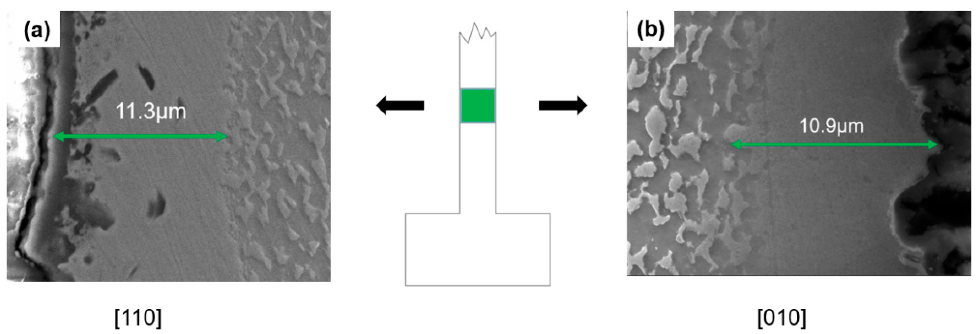
The X-ray backscattering Laue method was used to conduct the crystal orientation test along the axis of the test bar. The test bar with the primary orientation deviating less than 5 ° from the [001] direction was selected. With the consideration of the secondary orientation, the secondary orientation perpendicular to the side of the sample was controlled to deviate less than 5 ° from the [110] and [010] directions, respectively. The specific sampling method and sample size are shown in
Figure 1 and
Figure 2.
In order to ensure the surface quality of the thin wall sample, the 1 mm thick sample was processed by wire cutting, and then the surface and side of the sample were ground with 400, 600, 800, 1000, 1200, and 1500 silicon carbide sandpaper in turn. The error in the thickness direction of the sample was ±0.02 mm. Finally, the surface of the sample was polished with a diamond polish of 0.5 nm particles. The surface of the treated sample was required to be free of obvious scratches and other defects.
All creep tests were conducted according to the uniaxial tensile creep test method for metallic materials (GB/T 2039-2012), and the test conditions were 980 °C/220 MPa. After the test, samples were taken from the fracture area and test section of the sample, respectively, for polishing. The reagent prepared by CuSO4+100mL HCl+100mL C2H5OH was used for corrosion. All the microstructure characterizations were conducted by scanning electron microscope (SEM, Apreo S LoVac, FEI, Czech) equipped with an electron backscatter diffraction (EBSD) system (orientation analysis) operated at 25 kV and an energy dispersive spectroscopy (EDS) system operated at 20 kV. The fracture surface of the sample was treated by ultrasonic cleaning, the fracture morphology and microstructure were observed by SEM, and the surface oxide composition was analyzed by EDS. To further analyze the crystal change, EBSD was used to characterize the crystal rotation near the fracture surface of the sample.
3. Results and Discussion
In order to study the influence of wall thickness and secondary orientation on the creep property of the sample, thin wall samples with the second orientation of [110] and [010] are selected for testing. The creep life of thin wall samples with different thicknesses and Φ4 samples is shown in
Figure 3.
It can be seen from
Figure 3a that the creep life of the 0.3–0.7 mm thin-walled sample is far less than Φ4 round bar sample. The creep life of the thin wall sample with a wall thickness of 0.7 mm is 38% lower than that of the Φ4 round bar sample. The creep life of the 0.5 mm thin wall sample is 48% lower than that of the Φ4 round bar sample. The creep life of 0.3 mm thin wall sample is 60% lower than that of the Φ4 round bar sample. Since the creep life has decreased by 38% at 0.7 mm, which is much smaller than that of the Φ4 round bar sample, it can be determined that the Ni
3Al-based single crystal superalloy has produced the thickness debit effect when the wall thickness is smaller than 0.7 mm. At the same time, there is little difference between the creep life of the thin-walled sample with the second orientation of [110] and [010], that is, the secondary orientation has no obvious effect on the creep life of the thin-walled sample under this test condition. It can be seen from
Figure 3b that the strain of the Φ4 round bar sample is about 34%, while the average strain of 0.5 and 0.7 mm thin-walled sample is about 69%, and the strain of 0.3 mm thin-walled sample is about 36%. It can be seen from the strain that when the thickness debit effect is produced, the strain will also decrease significantly when the wall thickness reaches a certain value. Thin-walled samples take much shorter periods of 1% strain than round-bar samples. It can also be seen from the figure that the thin-walled sample has no obvious second stage of creep, and its strain and strain rate increase with time until the sample breaks.
Figure 4 is the fractured image of the sample with primary orientation [001] and secondary orientation [010]. It can be seen from
Figure 4a–c that the fracture surfaces of 0.3– 0.7 mm thin wall samples are rectangular, and the thickness of the fracture surfaces are 0.23, 0.32, and 0.48 mm, respectively. The height difference between the left and right sides of the fracture surface is very small, and there are dimples inside. The fracture surface of the standard round bar sample is basically circular, and the diameter changed from Φ4 to Φ3.4. The interior is full of tearing edges. It can be seen from the fracture surface of the thin-walled sample that the fracture surface thickness of the 0.3 mm sample decreases by 23%, and the average fracture surface thickness of the 0.5 and 0.7 mm samples decreases by 33.5%. Therefore, the deformation of the 0.3 mm sample in the length and thickness direction is smaller than that of the other two thickness samples, the differences regarding deformation are revealed in the following discussion part.
The white box in
Figure 4a is an obvious dimple area by observing the fracture surface characteristics, while a large area of cleavage surface appears on the left side. Therefore, it is speculated that the crack will initiate and expand from the right side. When the crack expands to the left side, the sample will break instantaneously due to the smaller load-bearing area. In
Figure 4b, a square cleavage surface is found in the white boxes on the left and right sides with tear edges around it, while the middle of the sample is a transient fracture zone with cleavage characteristics. A small dimple area is found in the white box in
Figure 4c, and there is an obvious strip-like transient fracture area in the middle of the fracture. In
Figure 4d tearing edges are distributed evenly at the fracture surface, and some cleavage surfaces are found on the left side of the fracture surface. Compared with
Figure 4a, the proportion of cleavage surface in
Figure 4d is far less than that in
Figure 4a, indicating that the instantaneous fracture zone in the round bar sample is smaller than that in the thin wall sample. It can be seen from the analysis in
Figure 4 that the three wall thickness samples all show the characteristics of mixed ductile-brittle fracture, of which the 0.3 mm thick sample has the largest transient fracture zone, indicating that the sample is more prone to fracture when the effective stress area changes in this thickness.
Figure 5 shows the composition and thickness comparison diagram of the affected zone of the sample test section, and the affected zone is the average value of the test section. It can be seen from
Figure 5a that the affected zone of the alloy thin wall sample consists of the NiO zone, Al and Ni oxides zone, and γ′- free zone.
Figure 5b shows the thickness of the affected zone in the test section of the thin-walled sample and the Φ4 round bar sample with the second orientation of [010]. It can be seen that the thickness of the affected zone of the Φ4 round bar sample is larger, about twice that of the thin-walled sample, but its overall proportion in the diameter direction is only 0.94%, far less than that of the thin-walled sample. The thickness of the affected zone of 0.3–0.7 mm thick, thin-walled samples has little difference, and the proportion in the thickness direction is 3.4–7.2%. Creep experiments found that the creep life of the 0.3 mm thick sample is about 70% of that of the 0.7 mm thick sample, but the thickness of the affected zone is not much different, so the thickness of the affected zone is not the main reason for the difference in the creep life of the two thin-walled samples.
Figure 6 shows the comparison of the affected zone in the test section of 0.7 mm thick samples with different secondary orientations. It can be seen from the figure that the thickness difference of the affected zone of the two thin-walled samples is not obvious, indicating that the second orientation of the sample in this experiment has no significant influence on the thickness of the affected zone.
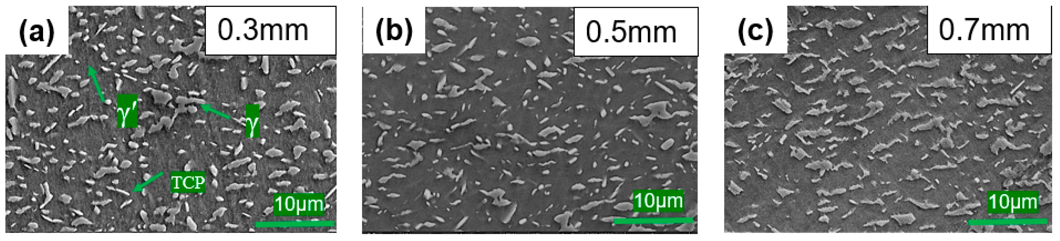
The microstructure comparison of the thin wall sample at 1 mm from the fracture surface is shown in
Figure 7. It can be seen from the figure that the fracture microstructure of the 0.3–0.7 mm thin-walled samples presents a fine γ phase, and γ phase of 0.3 mm and 0.5 mm samples is smaller than that of 0.7 mm samples. This kind of fine γ phase is surrounded by γ’ phase, forming many “islands”, that is, “Topology inversion” [
22]. In the evolution of γ/γ’ phase morphology, the volume fraction of γ’ raft changes [
23]. The γ’ phase is the main strengthening phase in single crystal superalloy, which is beneficial to the mechanical properties of the alloy at high temperatures, and the broken γ phase will form more γ/γ’ two-phase interfaces [
24]. The γ/γ’ two-phase interface is conducive to forming an interfacial dislocation network, which effectively hinders the dislocation movement and improves the mechanical properties of the alloy [
25].
The same as in other tests, it was found in this experiment that the maximum strain variable of thin-walled samples would increase with the increase in wall thickness [
8,
16]. From the perspective of maximum strain, the 0.7 mm sample has a longer creep life than the 0.3 mm sample may be due to its stronger deformation coordination ability. When the plastic strain of the alloy increases due to defects such as micro holes during the creep process of the sample, the thicker sample can extend the life of the sample through stronger deformation coordination ability, while the thinner sample is difficult to extend the creep life of the sample through deformation due to poor deformation coordination ability, so it will fracture when the alloy plastic strain is large, which is also consistent with the test results of the 0.3 mm sample with deformation of less than 0.7 mm sample mentioned above. At the same time, this is consistent with the study of Huttner et al., that the creep fracture strain and creep life decrease with the decrease of the wall thickness of the sample 1–0.3 mm [
26].
To verify this prediction, we analyzed the crystal rotation from the misorientation. EBSD was used to observe the misorientation at 1 mm of the fracture of 0.3 and 0.7 mm samples. The direction was parallel to the loading direction of the samples, and the length was about 650 μm. As can be seen from
Figure 8a, the maximum misorientation of the 0.3 mm sample in the Z direction is 2.08°. From
Figure 8b, the maximum misorientation of the 0.7 mm sample in the Z direction is 2.9°, that is, the thick sample has a greater degree of misorientation in the Z direction, and the thin sample has a smaller misorientation at fracture. This is consistent with the above results, the thinner the sample, the smaller the plastic deformation.
From the above research, it can be seen that the second orientation has little effect on the creep life of the alloy sample with a wall thickness of 0.3–0.7 mm. The thickness of the affected zone of the samples with different wall thicknesses is similar, and there is no significant difference, which indicates that the affected zone is not the main reason for affecting the creep life of the alloy. Through the analysis of the morphology, deformation, and microstructure of the fracture surface of the thin-walled sample, it can be inferred that the causes of the thickness debit effect of the single crystal alloy thin-walled sample are as follows: during the creep process, due to internal defects and surface affected zone, the effective force area of the alloy changes. According to Wen [
27], the necking degree of thin-walled specimens increases with the increase of wall thickness at high temperatures. Combined with the above research on the wall thickness change at the fracture, the increase of necking degree is equivalent to plastic deformation, for thicker samples, plastic deformation can be made to prolong the creep life of the alloy by better plastic deformation coordination ability, but the plastic coordination ability of thinner samples is poor. When the effective force area of the alloy changes, the way of prolonging the creep life by plastic deformation is weaker, and the plastic deformation sample of the after-creep fracture is smaller. The relationship between the thickness debit effect and deformation coordination ability has been studied by researchers. We know that the plastic deformation of the alloy is closely related to its activated slip system. Lv et al. [
21] studied the thickness debit effect from the slip systems, they believed that the six slip systems of the {111}<110>type and one slip system of the {111}<112>type were activated during the creep of the thin wall sample. The eight slip systems of {111}<110>type and the two slip systems of {111}<112>type of the thick sample were activated. Due to the different activated numbers of slip systems, the deformation coordination ability of thin samples is poor, which is consistent with the conclusion of this paper. The study of Huttner et al. [
26] also shows that there is a relationship between sample thickness and strain, and the strain of samples decreases with the decrease of wall thickness, which is consistent with the poorer plastic compatibility of thinner samples in this paper.
4. Conclusions
In this study, the thickness debit effect in creep performance of a Ni3Al-based single crystal superalloy was studied. Through comparative analysis of sample orientation, affected zone, and microstructure, the following main conclusions are obtained:
1. The Ni3Al-based single crystal superalloy studied in this experiment has an obvious thickness debit effect for 0.3–0.7 mm samples at 980 °C/220 MPa. It is found through the test that the second orientation [110] and [010] have no significant effect on the creep life of the thin wall samples.
2. By comparing the thickness of the affected zone of the sample with 0.3–0.7 mm thin wall, it is found that the thickness difference of the affected zone of the samples is not significant, indicating that the affected zone is not the main reason for the reduced life of the sample with a thin wall.
3. Based on the analysis of the microstructure of the thin-walled sample and the plastic deformation of the sample after fracture, a possible cause of the thickness debit effect was proposed. The thicker sample has better deformation coordination ability than the thinner one. When the stress condition of the sample changes due to defects in the creep process, the thicker sample can produce plastic deformation through its better deformation coordination ability and thus prolong the creep life, but the thinner sample can only prolong the creep life with smaller plastic deformation amount due to its poor deformation coordination ability. As a result, its creep life is shorter, and its fracture strain is smaller.


