Article

Using First-Principles Calculations to Investigate the Interfacial Properties of Ni(100)/Ni3Al(100) Eutectic Structures

1
School of Mechatronic Engineering and Automation, Foshan University, Foshan 528225, China
2
State Key Laboratory of Advanced Brazing Filler Metals & Technology, Zhengzhou Research Institute of Mechanical Engineering Co., Ltd., Zhengzhou 450001, China
3
China Innovation Academy of Intelligent Equipment (Ningbo) Co., Ltd., Ningbo 315700, China
4
School of Materials Science and Engineering, University of Shanghai for Science and Technology, Shanghai 200093, China
5
Ji Hua Laboratory, Foshan 528200, China
*
Authors to whom correspondence should be addressed.
Crystals 2023, 13(2), 199; https://doi.org/10.3390/cryst13020199
Submission received: 3 January 2023 / Revised: 18 January 2023 / Accepted: 19 January 2023 / Published: 22 January 2023
(This article belongs to the Special Issue Feature Papers in Crystalline Metals and Alloys in 2022–2023)

Abstract

:
In this paper, the interfacial stabilities of six different stacking interface configurations of Ni(100)/Ni3Al(100) eutectic structures with AlNi termination and Ni termination are calculated by using first-principles methods. The calculated adhesion work and interface energy indicate that the “Center” site stacking interface configurations are more stable than the “Top” and “Bridge” site stacking interface models. The partial density of states (PDOS) and the charge density difference confirm that the bonding characteristic of the Ni-terminated “Center” site stacking interface of the Ni(100)/Ni3Al(100) eutectic structure is metallic, while the bond at the AlNi-terminated “Center” site interface is a combination of covalent and metallic bonds. A comprehensive analysis of the interface energy, PDOS and charge density difference confirms that the AlNi-terminated “Center” site stacking interface configuration of the Ni(100)/Ni3Al(100) eutectic structure is the most stable eutectic interface model.

1. Introduction

γ/γ’ eutectic structures consist of a face-centered cubic Ni solid solution matrix (γ) and an L12-type ordered face-centered cubic intermetallic Ni3Al (γ’) phase. Ni/Ni3Al eutectic structures have received considerable attention as typical structures in Ni-based superalloys, coatings and composites [1,2,3]. The performance of materials strongly depends on the morphology, volume fraction and interfacial characteristics of their Ni/Ni3Al eutectic structures.
Many previous studies have been conducted on the solidification behavior and preferential growth orientation of Ni/Ni3Al eutectic structures in Ni-based superalloys under different processing conditions [4]. Ni/Ni3Al eutectic structures generally develop in the interdendritic regions of superalloys and eutectic composites, and they exhibit diversified morphologies, including isolated blocky, rosette-like, rod-like and continuous strip-like structures. The morphology and volume fraction of eutectic structures are closely related to the cooling rate, thermal gradient, alloy composition and external electromagnetic field [5,6,7,8]. In comparison to the Bridgman process, the downward directional solidification process enhances the cooling rate, refines the dendritic structure and decreases the Ni/Ni3Al eutectic structure size to obtain a homogeneous microstructure [5]. A high thermal gradient increases the solid volume fraction and conforms to the Bower–Brody–Flemings model, promoting the development of a fine Ni/Ni3Al eutectic structure in the center of interdendritic regions, which evolves into a petal-like coarse eutectic structure [6]. The addition of Re and Ru alloying elements increases the Ni/Ni3Al eutectic fractions and the segregation degree of Al and Ta alloying elements [7]. An external high-density current causes the dissolution of Ni/Ni3Al eutectic structures, promoting the transformation of the morphology of crisscrossed fine eutectic structures from block to bar shapes [8]. Therefore, in order to investigate the Ni/Ni3Al eutectic structures in alloys with various chemical compositions under different cooling rates, thermal gradients and external electromagnetic fields are essential to improve the performance of materials containing eutectic structures. In particular, the two Ni and Ni3Al phases under different conditions always have preferential growth orientations, and the orientation relationships (OR) of the Ni/Ni3Al interface have been determined to be (100)Ni||(100)Ni3Al, (110)Ni||(110)Ni3Al and (111)Ni||(111)Ni3Al [9,10]. Moreover, the (100)Ni||(100)Ni3Al interface is taken in this study as a typical coherent interface, which universally exists in eutectic structures. Consequently, it is of significance to clarify the interfacial characteristic of Ni/Ni3Al eutectic structures with preferential OR.
The interfacial characteristic between Ni and Ni3Al, including atomic structures, electronic structures and interfacial stability, is often the controlling factor limiting their practical applications [11,12]. Thus, determining it and understanding its influence on the comprehensive properties of Ni/Ni3Al eutectic structures are of great importance. For Ni-based single-crystal superalloys, the Ni matrix and Ni3Al precipitates are coherent [13]. To date, first-principles calculations based on the density functional theory (DFT) have been used to establish supercell and cluster models of the Ni/Ni3Al interface, further theoretically revealing the effects of alloying elements (Re, B, Cr, Ru, Co, Mo, W, Ta, Zr, Ti, Nb and Hf) on the thermodynamic stability and fracture strength of the interface between the Ni matrix and the precipitated Ni3Al phase [14,15,16,17]. However, the previous studies mainly focus on one or two types of interfacial models. For the Ni/Ni3Al eutectic structure in the interdendritic regions of superalloys and eutectic composites, the relationship of the interfacial characteristic with the preferential OR and eutectic structures, and the atomic and electronic structures and bonding characteristics of Ni/Ni3Al eutectic structures with preferential growth orientation remain unclear. Therefore, a systematic study of Ni(100)/Ni3Al(100) eutectic interfaces with diversified interface models is essential to clarify the interfacial properties of Ni/Ni3Al eutectic structures.
This study investigates the interfacial stability and electronic structures of six different interface models of Ni(100)/Ni3Al(100) eutectic structures calculated by employing first-principles calculations. The interface adhesion, interface energy and electronic structures of the diversified Ni(100)/Ni3Al(100) interface configurations are determined, providing an enhanced understanding of the most stable structures and the bonding characteristics of the Ni(100)/Ni3Al(100) eutectic interfaces with optimum stacking sites.

2. Computational Method

The first-principles calculations based on DFT were performed by using the Cambridge Sequential Total Energy Package (CASTEP) code [18]. The exchange and correlation energies of the bulk properties of pure Ni and Ni3Al, including the lattice constants, elastic constants and bulk modulus, were calculated by using the Generalized Gradient Approximation (GGA) of the Perdew–Burke–Ernzerhof (PBE) functions [19]. The K-point sampling in the first irreducible Brillouin zone was conducted by using the Monkhorst–Pack scheme. The plane-wave cutoff energy was set to 450 eV, the Monkhorst–Pack k-point mesh with 13 × 13 × 13 k points was utilized for the bulk Ni and Ni3Al, and 13 × 13 × 1 k points for the Ni/Ni3Al interfaces were utilized in the Brillouin zone integration. For the interface calculations, the self-consistent field (SCF) convergence threshold was set to 2.0 × 10⁻⁷ eV/atom, and the mean atomic force was reduced to 0.01 eV/Å. The equilibrium stress for each atom was converged to 0.02 GPa, the displacement was lower than 5.0 × 10⁻⁵ Å, and the system was considered to converge. The Kohn–Sham equation with the self-consistent field procedure was solved to obtain the electronic minimization and the ground state. The Broyden–Fletcher–Goldfarb–Shanno (BFGS) algorithm was employed to achieve the minimum energy state of the Ni/Ni3Al eutectic interface. For the surface models and interface configurations, periodic boundary conditions were applied, and a vacuum layer with a thickness of 10 Å was added on the interface and surface structures to avoid the interaction between the two identical surfaces.

3. Results and Discussion

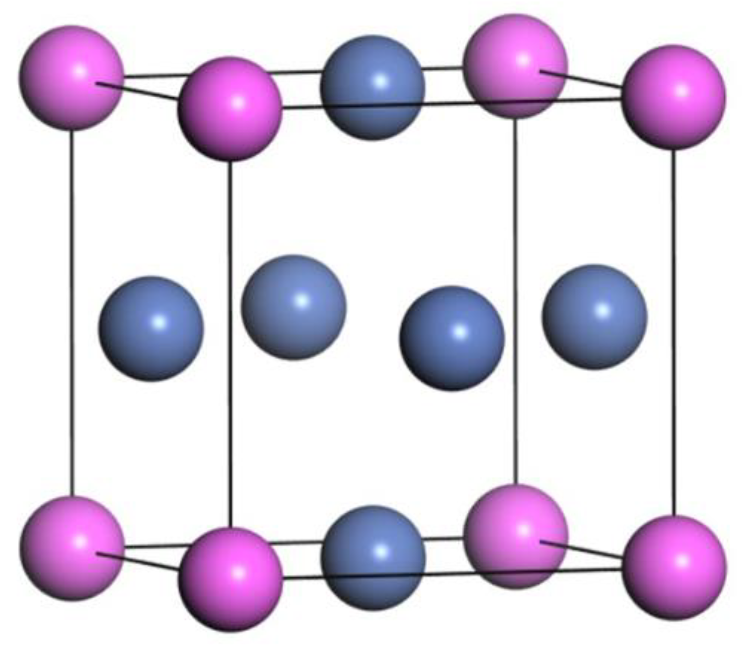
3.1. Bulk Properties of Ni and Ni3Al

The calculated lattice parameters (a), elastic constants (Cij) and bulk modulus (B) of the pure Ni and the pure Ni3Al crystal are listed in Table 1. For the pure Ni, the space group is Fm-3m (225), and the lattice constant and bulk modulus are a = 3.529 Å and B = 203.76 GPa, respectively. The results calculated by using GGA-PBE agree well with the values reported in the previous references. The difference between the experimental and theoretical elastic constants and bulk modulus is attributed to the different computational and experimental conditions. The space group of Ni3Al is Pm-3m (221), and the bulk structure of cubic Ni3Al is shown in Figure 1. The crystal structure belongs to the Cu3Au-type, and the Ni atoms occupy the 3c(0, 0.5, 0.5) Wyckoff positions, while the Al atoms occupy the 1a(0, 0, 0) positions. The lattice constant and bulk modulus calculated by using GGA-PBE are determined to be a = 3.577 Å and B = 182.64 GPa, respectively, which are in good agreement with the previous theoretical and experimental data. The comparison between the calculated and referenced values ensures the accuracy of the parameters and the precision in the calculation of the GGA-PBE functions. Therefore, the GGA-PBE functional is applied in the following calculations.

3.2. Surface Convergence

The required number of atomic layers for pure Ni and Ni3Al in the surface slab models should be determined to ensure that the surface slab models exhibit bulk-like interior properties. To determine the number of atomic layers in the following calculations of interfacial characteristics, a surface convergence test is conducted on the Ni and Ni3Al slabs versus slab thickness, and the results are listed in Table 2. For the Ni(100) surface, the odd layers with two identical surfaces are chosen to calculate the surface energy. The surface energy (γs) for more than nine atomic layers can be determined by the following equation [24]:
γ s = 1 2 A E surf N E bulk
where the factor 2 represents the two identical surfaces of the surface slab, A is the surface area, Esurf is the final energy of the Ni surface slab, Ebulk is the energy of each Ni atom in the bulk crystal, and N is the number of atoms in the surface slab. The Ni(100) surface energy is calculated and converges to 2.20 J/m2 for the surface models with more than nine layers, which is consistent with a previous study [21]. Therefore, the Ni surface slab model with nine atomic layers is adopted in the following calculation of interfacial characteristics of the Ni(100)/Ni3Al(100) eutectic structures.
For the Ni3Al(100) surface, there are two kinds of Ni3Al surfaces, namely, a Ni-terminated surface and a AlNi-terminated surface. The convergence test is conducted on the Ni3Al surface slabs by using the method described in Ref. [25]. To avoid the dipole effect of the surface configurations, the two free surfaces of Ni3Al(100) are identical. The odd layered slabs with 3, 5, 7, 9 and 11 layers are established to evaluate the convergences of the surfaces and to eliminate surface polarity. In the calculations, all of the atoms are relaxed to the local minimum positions. To quantitatively characterize the degree of relaxation during the calculations, the variation in the interlayer distance (Δij) for the optimized configuration after relaxation is calculated as (di,jd0)/d0 × 100%, where d0 is the bulk interlayer distance, and di,j is the average distance between the ith and jth layer. A positive Δij represents an increasing distance between the two layers and interlayer expansion, while a negative Δij indicates a decreasing distance and interlayer reduction. The results are shown in Table 3. The two Ni-terminated and AlNi-terminated surfaces with more than nine layers converge well, indicating that nine layers are thick enough for the convergence of the two Ni-terminated and AlNi-terminated Ni3Al(100) surfaces. Therefore, the nine-layered Ni and nine-layered Ni3Al slabs are chosen to construct the Ni(100)/Ni3Al(100) eutectic interfaces.

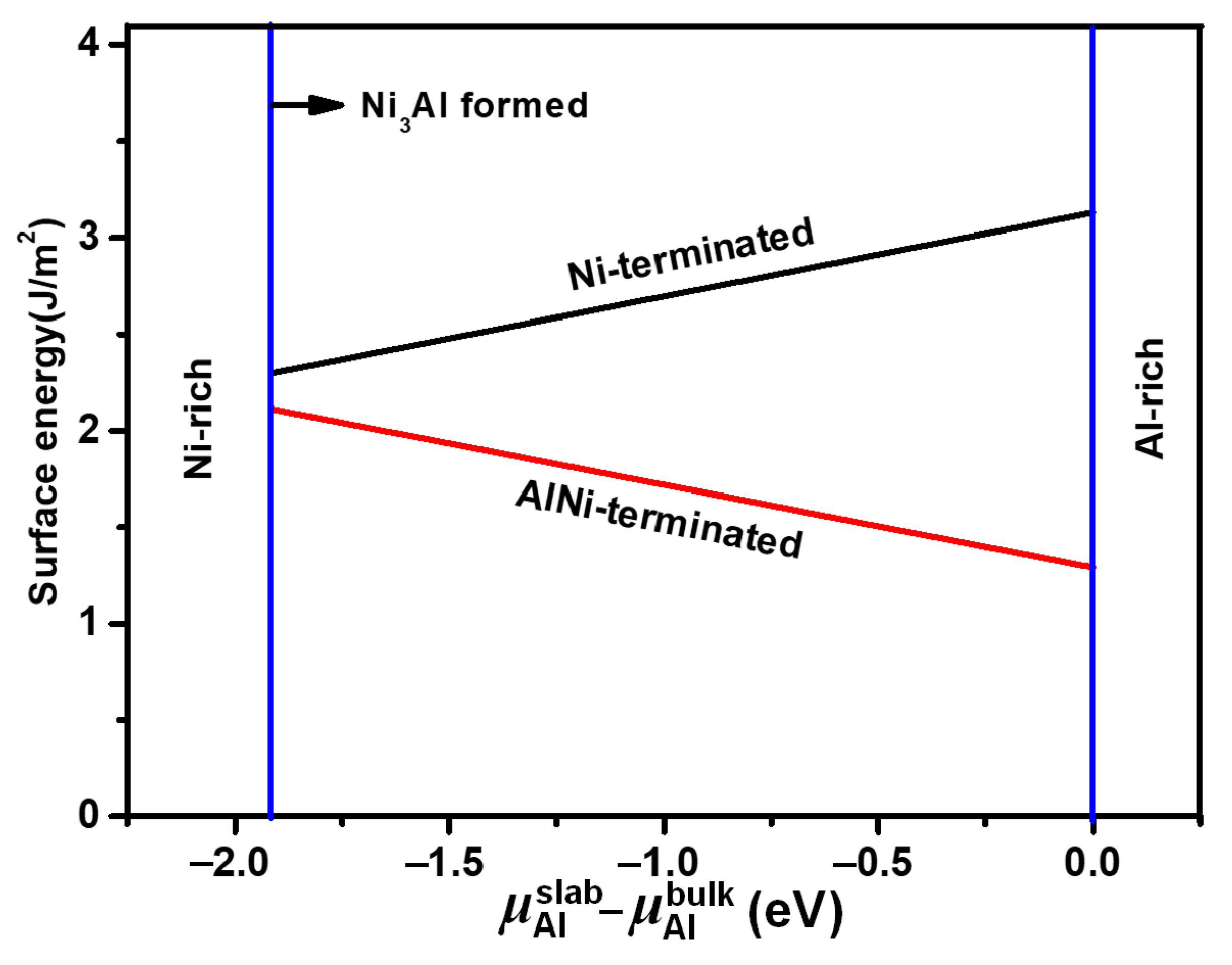
3.3. Surface Stability of Ni3Al Surfaces

The Ni3Al surface slab with symmetric terminations is non-stoichiometric, and the chemical potentials of the Ni and Al atoms should be considered for the calculation of the surface energy. The surface model is in equilibrium with the bulk and follows the relationships ( μ Ni 3 Al bulk = μ Al slab + 3 μ Ni slab ) and ( μ Ni 3 Al bulk = μ Al slab + 3 μ Ni slab + Δ H f 0 ), where μ Ni 3 Al bulk is the chemical potential of bulk Ni3Al; μ Al slab and μ Ni slab are the chemical potentials of the Al and Ni atoms, respectively; and Δ H f 0 is the formation enthalpy of bulk Ni3Al. The surface energies (γs) of the different Ni3Al surface models with non-stoichiometric characteristics can be determined by [26]
γ s = 1 2 A E slab N Ni 3 μ Ni 3 Al bulk + N Ni 3 N Al μ Al slab
where A is the area of the surface; Eslab is the total energy of the different surface models; NNi and NAl are the numbers of the Ni and Al atoms in the surface model, respectively. The Ni3Al(100) surface equilibrates the Ni3Al bulk and the chemical potentials of the Al and Ni atoms are less than the values in the bulk, indicating that stable atoms form the slab structures. In addition, μ Ni slab μ Ni bulk , and μ Al slab μ Al bulk ; the range of μ Al slab μ Al bulk can be determined as follows:
Δ H f 0 μ Al slab μ Al bulk 0
The surface energy of Ni3Al can be rewritten as follows:
γ s = 1 2 A E slab N Ni 3 μ Ni 3 Al bulk + N Ni 3 N Al μ Al bulk N Ni 3 N Al μ Al slab μ Al bulk
The surface energy variations of the Ni-terminated and AlNi-terminated surfaces versus the chemical potential difference of μ Al slab μ Al bulk are illustrated in Figure 2. There is a linear relationship between the surface energies and the chemical potential difference for the two surfaces. The Ni-terminated N3Al(100) surface energy increases with the increase in the chemical potential difference, while the surface energy decreases for the AlNi-terminated N3Al(100) surface. This is related to the different bonding characteristics of the Ni-terminated and AlNi-terminated Ni3Al(100) surfaces, as discussed in the following section, which covers the electronic structures of the eutectic interface. The surface energy of the AlNi-terminated surface is smaller than that of the Ni-terminated surface, and the values of the surface energies of the AlNi-terminated and Ni-terminated surfaces range from 1.29 J to 2.11 J and from 2.3 J to 3.13 J, respectively. The smaller value of the surface energy for the AlNi-terminated Ni3Al(100) surface indicates that it has better stability than the Ni-terminated Ni3Al(100) surface.

4. Interfacial Properties

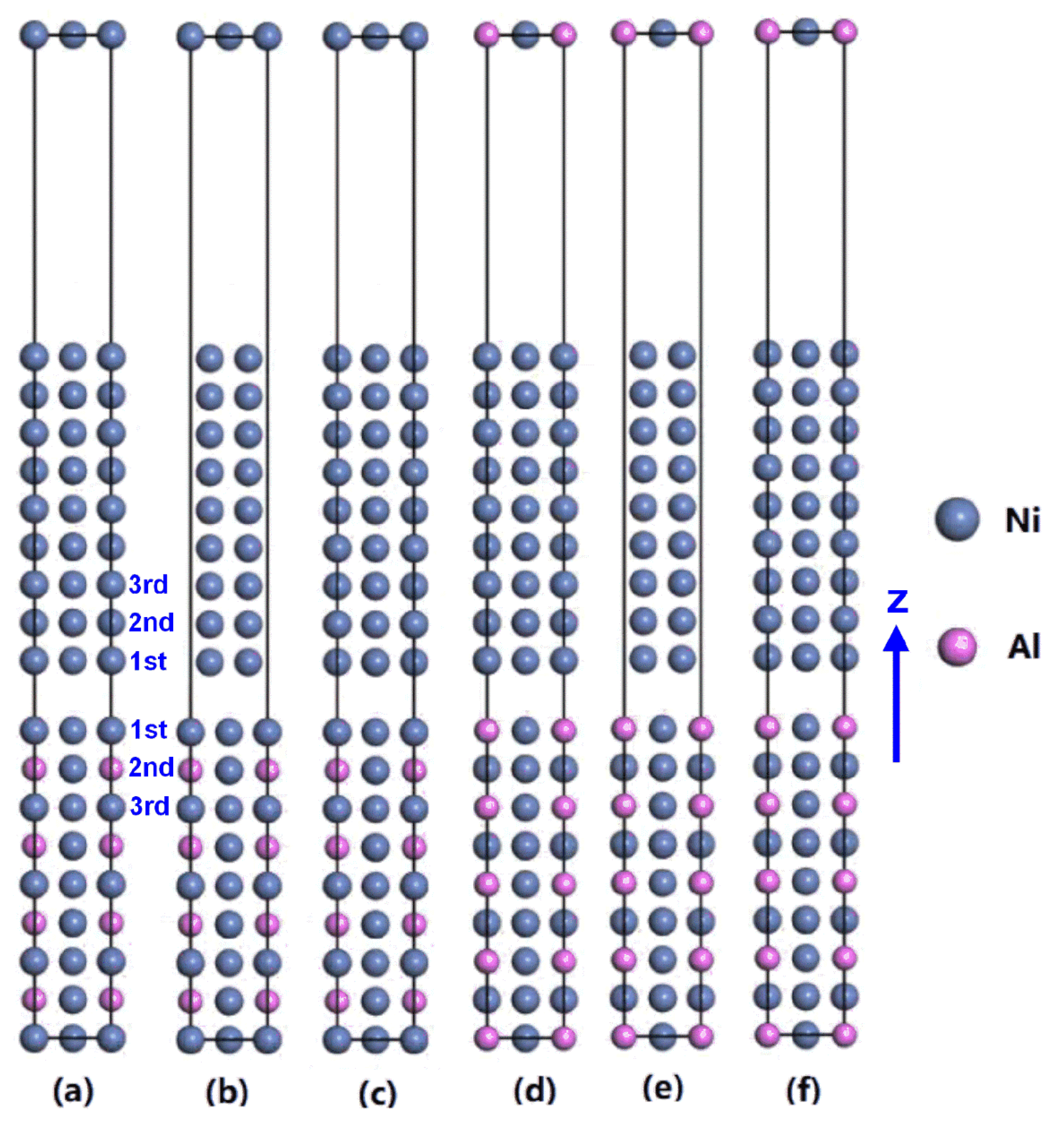
4.1. Atomic Structures of the Ni/Ni3Al Eutectic Interface

The nine-layered Ni and nine-layered Ni3Al surface slabs with periodic boundary conditions based on the surface convergence test were utilized to construct the Ni(100)/Ni3Al(100) eutectic interface models. A vacuum layer of 10 Å was built on top of the interface models to eliminate the interaction between the free surfaces of the Ni3Al and Ni slabs. The corresponding lattice mismatches (δ) for the interface models of Ni(100)/Ni3Al(100) were calculated using δ = 2(αNi3AlαNi)/(αNi3Al + αNi), where αNi3Al and αNi are the lattice constants of the Ni3Al and Ni phases, respectively. The value of the lattice mismatches was determined to be 1.34%, indicating a coherent Ni(100)/Ni3Al(100) interface and the neglect of the interfacial strain in the calculation of the interfacial characteristics. Three different stacking sequences of the Ni atoms in the layers of the Ni(100) surface on each of the Ni3Al(100) Ni-terminated and AlNi-terminated surfaces were considered to build six different interface models of Ni(100)/Ni3Al(100) eutectic structures, namely, the Ni-terminated and “Top” site stacking interface, the Ni-terminated and “Bridge” site stacking interface, the Ni-terminated and “Center” site stacking interface, the AlNi-terminated and “Top” site stacking interface, the AlNi-terminated and “Bridge” site stacking interface, and the AlNi-terminated and “Center” site stacking interface, as shown in Figure 3. For the Ni-terminated and AlNi-terminated surfaces, the “Top” site stacking interface shown in Figure 3a,d indicates that the interfacial Ni atoms in the first layer of the Ni(100) surface were placed right on the interfacial Ni or Al atoms of the Ni3Al(100) slab. The “Bridge” site stacking interface shown in Figure 3b,e indicates that the interfacial Ni atoms in the first layer of the Ni(100) surface were located in the middle site between the Ni and Al atoms in the Ni3Al(100) slab. The “Center” site stacking interface shown in Figure 3c,f indicates that the interfacial Ni atoms in the first layer of the Ni(100) surface were located right above the second layer of the Ni3Al(100) slab. All the atoms in the interface models can be relaxed freely in the three dimensions.

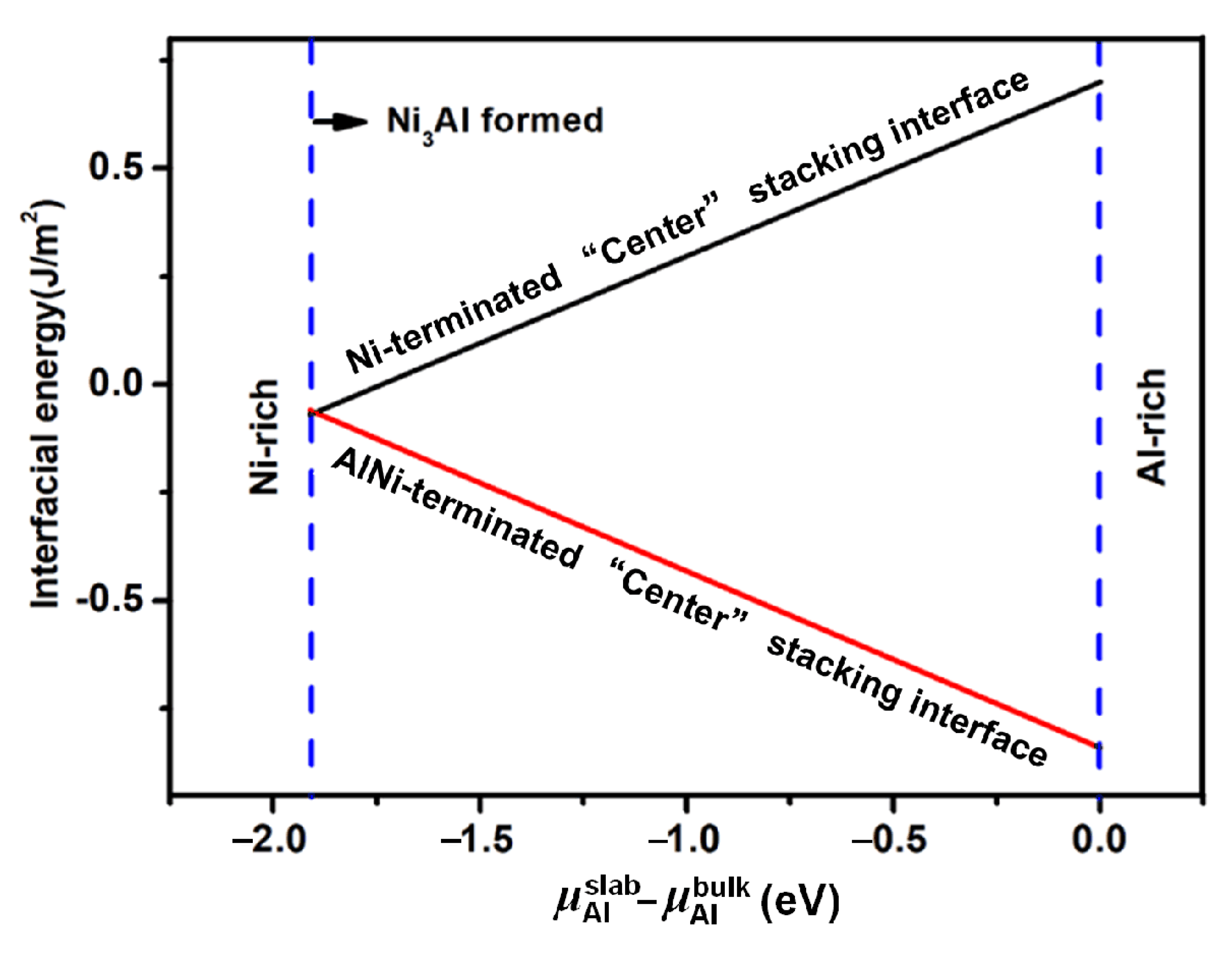
4.2. Interfacial Stability

The interfacial adhesion work (Wad) is commonly used to evaluate the interfacial stability of various Ni(100)/Ni3Al(100) eutectic structures, and it is defined as the reversible energy required to separate the Ni/Ni3Al interface into two free surfaces. A higher interfacial adhesion work represents a stable interface. The interfacial adhesion work of the Ni(100)/Ni3Al(100) eutectic structure is determined via the energy of the Ni(100) surface slab (ENi), the energy of the Ni3Al(100) surface slab ( E Ni 3 Al ) after relaxation and the interfacial energy of the Ni(100)/Ni3Al(100) eutectic structure after full relaxation (Einterface):
W a d = 1 A E Ni + E Ni 3 Al E interface
where A is the interfacial area of the Ni(100)/Ni3Al(100) eutectic structure. After the atoms in the interface are fully relaxed to the equilibrium position, the variation of the total energy of the interface is calculated with the interfacial distance variation d0, which is the distance between the first layer of the Ni and Ni3Al slabs along the z direction. The optimal d0 and Wad are listed in the “Fully Relaxed” column in Table 4. Compared to the “Top” and “Bridge” site stacking configurations, the interfacial adhesion work of “Center” site stacking configuration is the highest for the both Ni-terminated and AlNi-terminated Ni(100)/Ni3Al(100) eutectic interfaces. A larger adhesion work indicates a greater stability of the interface. This indicates that the Ni-terminated and AlNi-terminated “Center” (100) interfaces are more stable than the “Top” and “Bridge” site stacking interface models. Consequently, the Ni-terminated and AlNi-terminated “Center” site stacking interface configurations, rather than the “Top” and “Bridge” site stacking interface models, are further investigated in this study.
To further evaluate the interfacial stability of the different Ni(100)/Ni3Al(100) eutectic interface configurations, the interfacial energies (γ) of the Ni-terminated and AlNi-terminated “Center” site stacking interface models are calculated by using the following equation [26].
γ = 1 A E interface N Ni Ni 3 Al 3 μ Ni 3 Al bulk N Ni Ni 3 Al 3 N Al μ Al slab N Ni Ni μ Ni bulk σ Ni σ Ni 3 Al
where A is the interface area; Einterface is the interfacial energy of the Ni(100)/Ni3Al(100) eutectic structure after full relaxation; NAl is the number of Al atoms in the Ni3Al(100) slab; N Ni Ni 3 Al and N Ni Ni are the number of Ni atoms in the Ni3Al(100) and Ni(100) slabs, respectively; μ Ni 3 Al bulk is the chemical potential of Ni3Al; μ Ni bulk is the chemical potential of the Ni atom in the Ni bulk; μ Al slab is the chemical potential of the Al atom in the interface; and σ Ni and σ Ni 3 Al are the surface energies of the Ni(100) and Ni3Al(100) surfaces, respectively. For the two Ni-terminated and AlNi-terminated “Center” site stacking interface models, the interfacial energy variation versus the chemical potential difference of Al ( μ Al slab μ Al bulk ) is shown in Figure 4. The interface energy of the Ni-terminated “Center” site stacking interface monotonously increases from −0.07 to 0.7 J/m2 with the increasing chemical potential difference, while the interface energy of the AlNi-terminated “Center” site stacking interface decreases from −0.06 to −0.84 J/m2. The interfacial energy of the AlNi-terminated “Center” site stacking interface is lower than that of the Ni-terminated “Center” site stacking interface. This indicates that the AlNi-terminated “Center” site stacking Ni(100)/Ni3Al(100) eutectic interface has a high stability and is more stable than the Ni-terminated “Center” site stacking interface model.

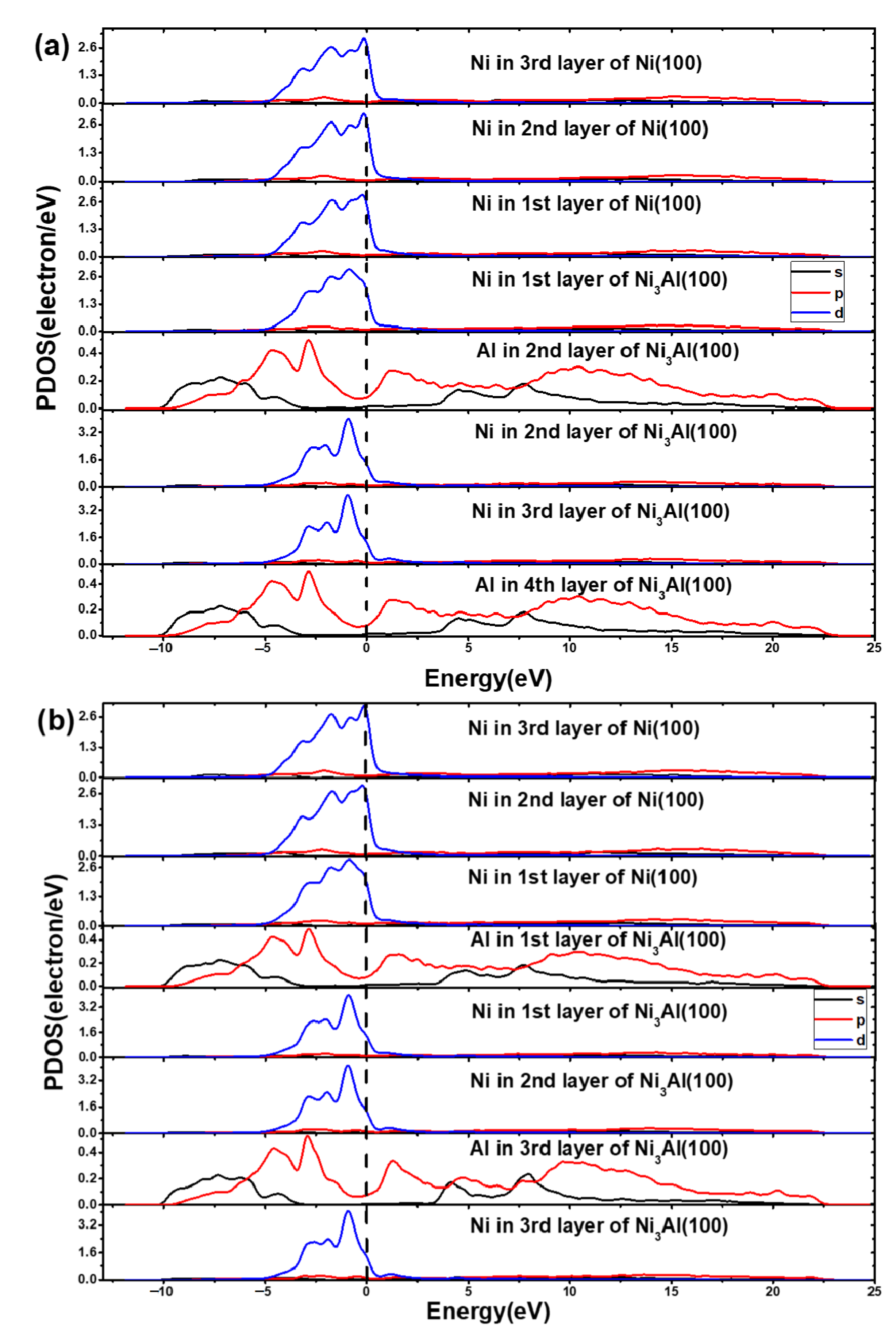
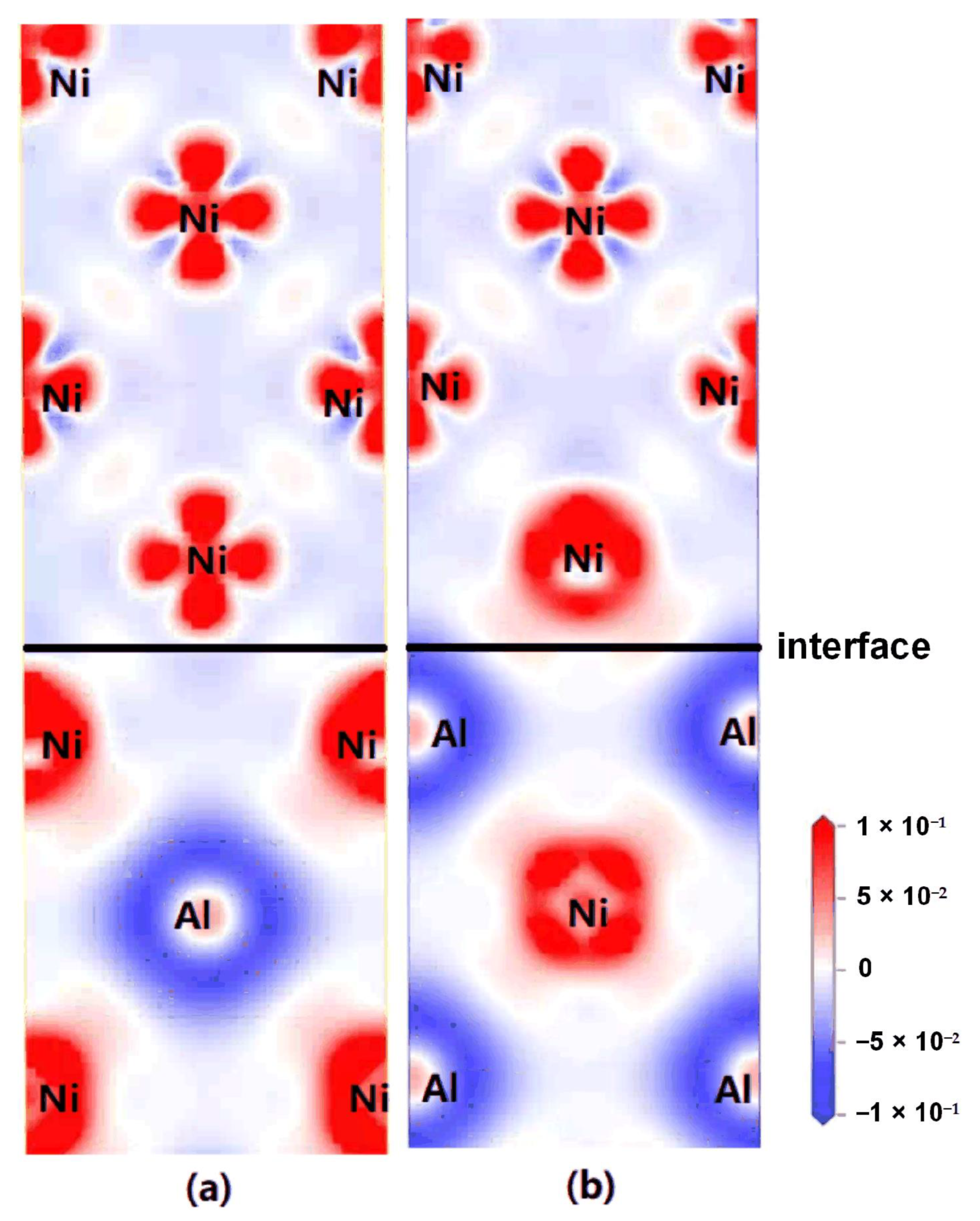
4.3. Electronic Structure

To further explore the interfacial characteristic and stability of the Ni-terminated and AlNi-terminated “Center” site stacking interface models of the Ni(100)/Ni3Al(100) eutectic structures, the partial density of states (PDOS) and the charge density difference are calculated to elucidate the electronic structure and the bonding characteristics of the two different interface models. The obtained PDOS for the AlNi-terminated and Ni-terminated “Center” site stacking interfaces of the Ni(100)/Ni3Al(100) eutectic structures are presented in Figure 5. The vertical dashed line represents the Fermi level. The 1st, 2nd and 3rd layers are the same as the layers in Figure 3, and the 3rd and higher layers of the Ni and Ni3Al sides have similar bulk Ni and Ni3Al properties. For the Ni-terminated “Center” site stacking Ni(100)/Ni3Al(100) interface, the PDOS at the interface is different from that of the interior layers, indicating the electron redistribution of the interfacial atoms (Figure 5a). The interfacial Ni atoms have the same PDOS and occupy more states near the Fermi level with no depletion, indicating the metallic bonding characteristics of the Ni(100)/Ni3Al(100) interface. For the AlNi-terminated “Center” site stacking Ni(100)/Ni3Al(100) interface, the PDOS of the interfacial Al atoms are larger than the PDOS of those in the bulk or the interior one, and the first-layer Ni atoms in the Ni(100) slab have a weak depletion, as shown in Figure 5b. Based on the difference between the PDOS of the interface and the PDOS of the interior layers, the overlapping interfacial Ni and Al atoms near the Fermi level reflect the orbital hybridization and the formation of covalent bonds between Ni-3d and Al-2p. Therefore, the bonding characteristic of the AlNi-terminated “Center” site stacking interface of the Ni(100)/Ni3Al(100) eutectic structures is covalent with metallic bonding.
Figure 6 shows the charge density difference for the fully relaxed Ni-terminated and AlNi-terminated “Center” site stacking interfaces of the Ni(100)/Ni3Al(100) eutectic structures. The solid horizontal lines represent the interfaces of the two Ni(100)/Ni3Al(100) eutectic interface models, the red area denotes the enrichment of electrons, and the blue area represents the loss of electrons. For the Ni-terminated “Center” site stacking interface, the charge depletion is mainly concentrated in the Al atoms in the Ni3Al(100) slab and partially concentrated around the Ni atoms in the Ni(100) slab. The original interfacial charge distribution is similar to that in the Ni(100) slab and the Ni3Al(100) slab, indicating no obvious charge transfer or redistribution near the interface and the metallic bonding characteristic at the Ni-terminated “Center” site stacking interface of the Ni(100)/Ni3Al(100) eutectic structures, as shown in Figure 6a. For the AlNi-terminated “Center” site stacking interface, there is an obvious charge accumulation in the Ni atoms at the interface, and the charge accumulation region extends to the second layer of the Ni(100) slab. The interfacial charge distribution is similar to that in the Ni3Al(100) slab, indicating the combined interaction of covalent and metallic bonding characteristics (Figure 6b). Additionally, the covalent bond is stronger than the metallic bond. Therefore, the bonding characteristic of the AlNi-terminated “Center” site stacking interface of the Ni(100)/Ni3Al(100) eutectic structures is more stable than that of the Ni-terminated “Center” site stacking interface model. These results are consistent with the conclusion from the PDOS.

5. Conclusions

Six different Ni-terminated and AlNi-terminated interface models of Ni(100)/Ni3Al(100) eutectic structures, containing “Top”, “Bridge” and “Center” site stacking configurations, were established for an investigation into the interfacial stability of eutectic structures. The interface adhesion, interface energy and electronic structures were calculated to determine the most stable interfacial configuration of the Ni(100)/Ni3Al(100) eutectic structures. The main conclusions are summarized as follows:
  • A nine-layered Ni(100) slab and a nine-layered Ni3Al(100) slab with AlNi termination and Ni termination were utilized to establish six different interface models of Ni(100)/Ni3Al(100) eutectic structures, namely, Ni-terminated and AlNi-terminated “Top” site stacking interface, Ni-terminated and AlNi-terminated “Bridge” site stacking interface, and Ni-terminated and AlNi-terminated “Center” site stacking interface configurations.
  • The AlNi-terminated “Center” site stacking interface model of the Ni(100)/Ni3Al(100) eutectic structure was determined to be the most stable interfacial configuration from a comprehensive analysis of the adhesion work, interfacial energy and electronic structures.
  • The PDOS and charge density difference indicated the combined bonding characteristics of covalent and metallic bonds at the interface of the AlNi-terminated and “Center” site stacking interface of the Ni(100)/Ni3Al(100) eutectic structure, which had a higher stability than the Ni-terminated and “Center” site stacking interfacial model.

Author Contributions

Methodology, Y.J. and J.Y.; Validation, W.F. and J.Q.; Formal analysis, S.Z.; Data curation, J.Y.; Writing—original draft, Z.D.; Writing—review and editing, Z.D. and T.Y.; Visualization, S.Z.; Supervision, W.L. and J.Q.; Funding acquisition, W.L. All authors have read and agreed to the published version of the manuscript.

Funding

This work was financially supported by the National Natural Science Foundation of China (No. 51904187), the Project funded by the China Postdoctoral Science Foundation (No. 2022M712919), the Open Project of State Key Laboratory of Advanced Brazing Filler Metals and Technology (SKLABFMT-2021-03), the Science and Technology Program of Guangdong Province (X220391TH220) and the Scientific Research Project of Education Department of Guangdong Province (2022KCXTD029, 2022KTSCX125).

Data Availability Statement

Data available on request due to restrictions e.g., privacy or ethical.

Conflicts of Interest

The authors declare no conflict of interest.

References

  1. Ren, H.S.; Xiong, H.P.; Long, W.M.; Chen, B.; Shen, Y.X.; Pang, S.J. Microstructures and mechanical properties of Ti3Al/Ni-based superalloy joints brazed with AuNi filler metal. J. Mater. Sci. Technol. 2019, 35, 2070–2078. [Google Scholar] [CrossRef]
  2. Wang, H.F.; Su, H.J.; Zhang, J.; Zhang, Y.B.; Yue, Q.Z.; Liu, L.; Huang, T.W.; Yang, W.C.; Fu, H.Z. Investigation on solidification path of Ni-based single crystal superalloys with different Ru contents. Mater. Charact. 2017, 130, 211–218. [Google Scholar] [CrossRef]
  3. Cheng, G.P.; He, Y.Z. Two phase matrix of Ni3Al and γ-Ni coatings prepared by laser cladding. Appl. Mech. Mater. 2011, 66–68, 2005–2009. [Google Scholar] [CrossRef]
  4. Wilson, B.C.; Cutler, E.R.; Fuchs, G.E. Effect of solidification parameters on the microstructures and properties of CMSX-10. Mater. Sci. Eng. A 2008, 479, 356–364. [Google Scholar] [CrossRef]
  5. Wang, F.; Ma, D.; Zhang, J.; Lin, L.; Bogner, S.; Polaczek, A.B. Effect of local cooling rates on the microstructures of single crystal CMSX-6 superalloy: A comparative assessment of the Bridgman and the downward directional solidification processes. J. Alloys Compd. 2014, 616, 102–109. [Google Scholar] [CrossRef]
  6. Wang, F.; Ma, D.; Zhang, J.; Bogner, S.; Polaczek, A.B. Solidification behavior of a Ni-based single crystal CMSX-4 superalloy solidified by downward directional solidification process. Mater. Charact. 2015, 101, 20–25. [Google Scholar] [CrossRef]
  7. Liu, G.; Liu, L.; Ai, C.; Ge, B.M.; Zhang, J.; Fu, H.Z. Influence of withdrawal rate on the microstructure of Ni-base single-crystal superalloys containing Re and Ru. J. Alloys Compd. 2011, 509, 5866–5872. [Google Scholar] [CrossRef]
  8. Qin, S.Y.; Hao, J.Q.; Yan, L.G.; Zhang, X.F. Ultrafast solution treatment to improve the comprehensive mechanical properties of superalloy by pulsed electric current. Scripta Mater. 2021, 199, 113879. [Google Scholar] [CrossRef]
  9. Sheffler, K.D.; Barkalow, R.H.; Yuen, A.; Leverant, G.R. The anisotropy of deformation and fracture in a directionally solidified Ni/Ni3Al-Ni3Cb lamellar eutectic alloy. Metall. Trans. A 1977, 8, 83–89. [Google Scholar] [CrossRef]
  10. Wang, F.; Ma, D.; Polaczek, A.B. Preferred growth orientation and microsegregation behaviors of eutectic in nickel-based single-crystal superalloy. Sci. Technol. Adv. Mater. 2015, 16, 025004. [Google Scholar] [CrossRef]
  11. Chen, D.; Ma, X.L.; Wang, Y.M. First-principles study of the interfacial structures of Au/MgO(001). Phys. Rev. B 2007, 75, 125409. [Google Scholar] [CrossRef] [Green Version]
  12. Yang, Q.G.; Lu, C.; Han, Y.; Chen, X.H.; Yang, J.; Huang, J.H.; Chen, S.H.; Ye, Z. Influence of Cu/W interfacial structure on the resistance against harmful helium atoms: A mechanism analysis. J. Alloys Compd. 2022, 903, 163817. [Google Scholar] [CrossRef]
  13. Peng, P.; Zhou, D.W.; Liu, J.S.; Yang, R.; Hu, Z.Q. First-principles study of the properties of Ni/Ni3Al interface doped with B or P. Mater. Sci. Eng. A 2006, 416, 169–175. [Google Scholar] [CrossRef]
  14. Gong, X.F.; Yang, G.X.; Fu, Y.H.; Xie, Y.Q.; Zhuang, J.; Ning, X.J. First-principles study of Ni/Ni3Al interface strengthening by alloying elements. Compt. Mater. Sci. 2009, 47, 320–325. [Google Scholar] [CrossRef]
  15. Wu, Y.X.; Zhang, W.L.; Guo, J.; Hou, J.S.; Li, X.Y.; Huang, R.Z.; Ma, X.F.; Zhang, Q.F. The first-principles study on the occupation behavior and the ductility mechanism of Zr in Ni-Ni3Al system with lattice misfit. J. Mater. Sci. Technol. 2014, 30, 517–522. [Google Scholar] [CrossRef]
  16. Wen, Q.H.; Wang, M.X.; Kong, L.T.; Zhu, H. Effects of alloying elements on the Ni/Ni3Al interface strength and vacancy diffusion behavior. J. Appl. Phys. 2020, 128, 175307. [Google Scholar] [CrossRef]
  17. Ahmed, F.A.; Xue, H.T.; Tang, F.L.; An, J.P.; Luo, Y.Q.; Lu, X.F.; Ren, J.Q. Segregation of alloying elements and their effects on the thermodynamic stability and fracture strength of γ-Ni/γ’-Ni3Al interface. J. Mater. Sci. 2020, 55, 12513–12524. [Google Scholar] [CrossRef]
  18. Yang, T.X.; Wei, M.Z.; Ding, Z.Y.; Han, X.J.; Li, J.G. Ab initio calculations on the Mg/TiN heterogeneous nucleation interface. J. Phys. Chem. Solids 2020, 143, 109479. [Google Scholar] [CrossRef]
  19. Yang, T.X.; Chen, X.H.; Li, W.; Han, X.J.; Liu, P. First-principles calculations to investigate the interfacial energy and electronic properties of Mg/AlN interface. J. Phys. Chem. Solids 2022, 167, 110705. [Google Scholar] [CrossRef]
  20. Woodward, C.; Walle, A.; Asta, M.; Trinkle, D.R. First-principles study of interfacial boundaries in Ni-Ni3Al. Acta Mater. 2014, 75, 60–70. [Google Scholar] [CrossRef]
  21. Wang, C.; Wang, C.Y. Ni/Ni3Al interface: A density functional theory study. Appl. Surf. Sci. 2009, 255, 3669–3675. [Google Scholar] [CrossRef]
  22. Kayser, F.X.; Stassis, C. The elastic constants of Ni3Al at 0 and 23.5 °C. Phys. Status Solidi A 1981, 64, 335–342. [Google Scholar] [CrossRef]
  23. Wu, Q.; Li, S.S. Alloying element additions to Ni3Al: Site preferences and effects on elastic properties from first-principles calculations. Compt. Mater. Sci. 2012, 53, 436–443. [Google Scholar] [CrossRef]
  24. Fiorentini, V.; Methfessel, M. Extracting convergent surface energies from slab calculations. J. Phys. Condens. Matter 1999, 8, 6525. [Google Scholar] [CrossRef] [Green Version]
  25. Guo, X.; Zhou, J.T.; Zhang, X.X.; Yang, P.; Ren, J.Q.; Lu, X.F. Effect of alloying elements on the interface of fcc-Fe/Ni3Al by first principle calculations. Comp. Mater. Sci. 2022, 214, 111673. [Google Scholar] [CrossRef]
  26. Li, J.; Zhang, M.; Zhou, Y. First-principles study of Al/Al3Ti heterogeneous nucleation interface. Appl. Surf. Sci. 2014, 307, 593–600. [Google Scholar] [CrossRef]
Figure 1. Crystal model of Ni3Al. The gray and purple balls correspond to the Ni and Al atoms, respectively.
Crystals 13 00199 g001
Figure 2. Relationship between surface energy of Ni-terminated and AlNi-terminated Ni3Al(100) and chemical potential difference of μ Al slab μ Al bulk .
Crystals 13 00199 g002
Figure 3. Side view of the six different interface models of Ni(100)/Ni3Al(100) eutectic structures: (a) Ni-terminated Ni3Al and “Top” site, (b) Ni-terminated Ni3Al and “Bridge” site, (c) Ni-terminated Ni3Al and “Center” site, (d) AlNi-terminated Ni3Al and “Top” site, (e) AlNi-terminated Ni3Al and “Bridge” site, (f) AlNi-terminated Ni3Al and “Center” site. The gray and pink colored spheres represent the Ni and Al atoms, respectively. The first three layers of Ni-terminated interface model are defined and illustrated, and they are the same as those of the other interface models. The z direction is the relaxation direction during geometry optimization.
Crystals 13 00199 g003
Figure 4. The interfacial energy variation versus chemical potential difference of Al ( μ Al slab μ Al bulk ) for the different interface models of Ni(100)/Ni3Al(100) eutectic structure. The AlNi-terminated “Center” site stacking interface has a negative and smaller interfacial energy in the whole range.
Crystals 13 00199 g004
Figure 5. Partial density of states (PDOS) of the different Ni(100)/Ni3Al(100) eutectic interface models: (a) Ni-terminated “Center” stacking interface, (b) AlNi-terminated “Center” stacking interface. The dashed line represents the Fermi level, and the number of layers corresponds to the number of layers in Figure 3.
Crystals 13 00199 g005
Figure 6. Charge density difference for the two “Center” site stacking interface models of Ni(100)/Ni3Al(100) eutectic structures: (a) Ni-terminated “Center” stacking interface, (b) AlNi-terminated “Center” stacking interface. The solid horizontal line denotes the interface of the two interface models of Ni(100)/Ni3Al(100) eutectic structures.
Crystals 13 00199 g006
Table 1. The calculated lattice constants (a), elastic constants (Cij) and bulk modulus (B) of pure Ni and Ni3Al crystal.
a(Å)C11(GPa)C12(GPa)C44(GPa)B(GPa)
NiPBE3.529283.78178.75110.95203.76
Exp. [20]3.524248.1154.9124.2186
Cal. [21]3.526303.4205.7136.3196.8
Ni3AlPBE3.577240.14153.89124.59182.64
Exp. [22]3.567224.5148.6124.4173.9
DFT [23]3.58243.8148.7123.4182.4 [21]
Table 2. Calculated surface energies of different Ni(100) surfaces versus atomic layers.
Atomic Layer (n)Surface Energy (J/m2)
Ni (100)32.24
52.22
72.21
92.20
112.19
Table 3. Interlayer distance variation (Δij) convergences of the two Ni-terminated and AlNi-terminated Ni3Al(100) surfaces versus the number of atomic layers.
TerminationInterlayerSlab Thickness
357911
Ni terminationΔ12−3.93%−4.14%−4.25%−4.32%−4.24%
Δ23 0.02%−0.04%−0.56%−0.55%
Δ34 0.05%−0.39%−0.45%
Δ45 −0.64%−0.75%
Δ56 −0.003%
AlNi terminationΔ12−3.22%−3.02%−3.08%−3.02%−3.02%
Δ23 −0.21%−0.44%−0.39%−0.39%
Δ34 −0.36%−0.31%−0.26%
Δ45 0.03%0.02%
Δ56 0.04%
Table 4. Adhesion work (Wad) and interfacial distance variation (d0) of the Ni-terminated and AlNi-terminated Ni(100)/Ni3Al(100) interface models after relaxation.
TerminationStackingFully Relaxed
d0(Å)Wad(J/m2)
Ni
termination
Top2.302.36
Bridge2.053.19
Center1.734.34
AlNi
termination
Top2.332.26
Bridge2.13.03
Center1.784.15
Disclaimer/Publisher’s Note: The statements, opinions and data contained in all publications are solely those of the individual author(s) and contributor(s) and not of MDPI and/or the editor(s). MDPI and/or the editor(s) disclaim responsibility for any injury to people or property resulting from any ideas, methods, instructions or products referred to in the content.

