
Full Stokes Polarization Imaging Based on Broadband Liquid Crystal Polarization Gratings

Abstract
:1. Introduction
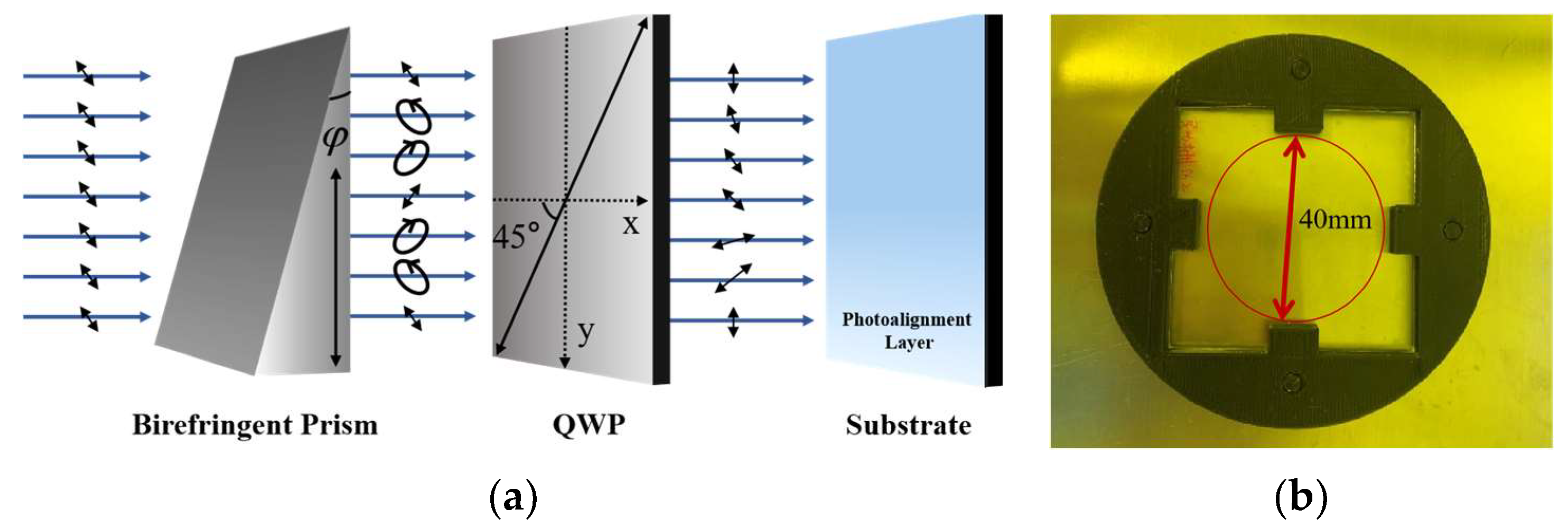
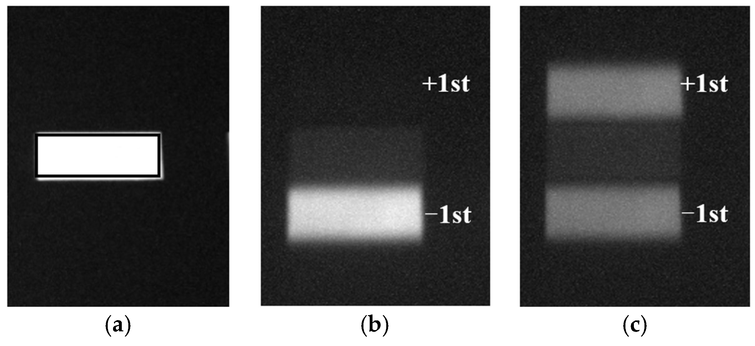
2. Principle
3. Linear Stokes Detection
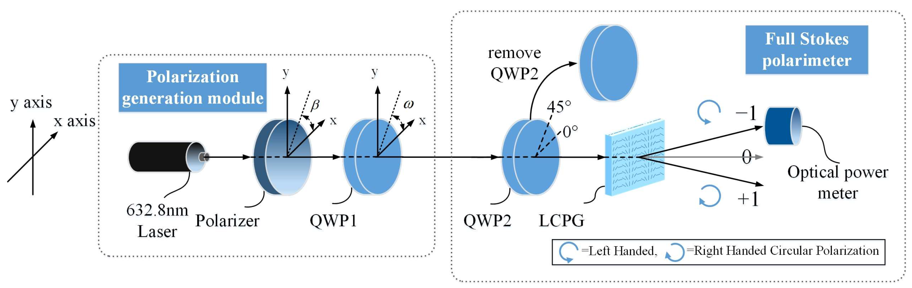
3.1. Optimal Design of Polarization Detection System
3.2. Linear Stokes Parameter Reconstruction
4. Full Stokes Detection
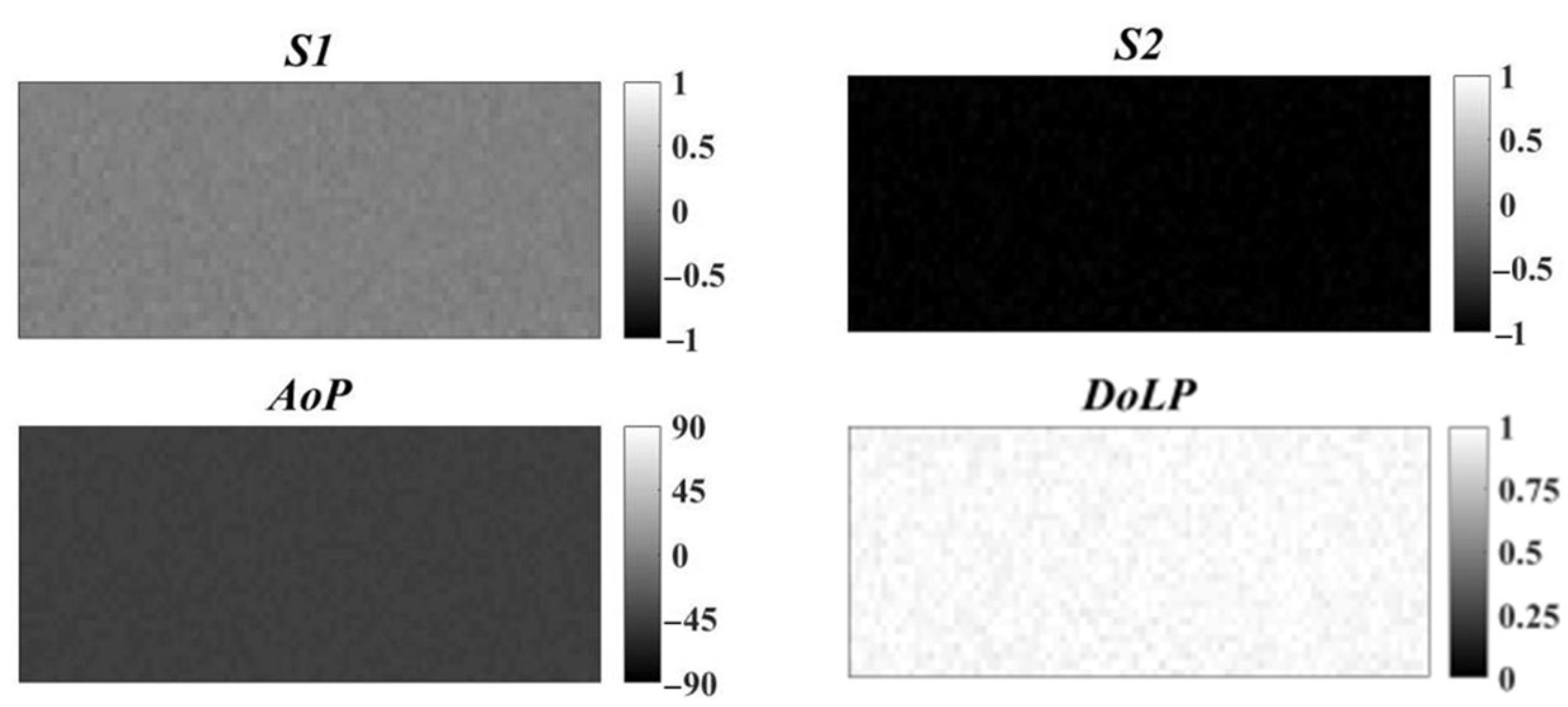
Full Stokes Parameter Reconstruction
5. Conclusions
Author Contributions
Funding
Data Availability Statement
Conflicts of Interest
References
- Rubin, N.A.; D’Aversa, G.; Chevalier, P.; Shi, Z.; Chen, W.T.; Capasso, F. Matrix Fourier Optics Enables a Compact full-Stokes Polarization Camera. Science 2019, 365, 43. [Google Scholar] [CrossRef] [PubMed]
- Basiri, A.; Chen, X.; Bai, J.; Amrollahi, P.; Carpenter, J.; Holman, Z.; Wang, C.; Yao, Y. Nature-inspired chiral metasurfaces for circular polarization detection and full-Stokes polarimetric measurements. Light Sci. Appl. 2019, 8, 78. [Google Scholar] [CrossRef] [PubMed] [Green Version]
- Dai, M.; Wang, C.; Qiang, B.; Wang, F.; Ye, M.; Han, S.; Luo, Y.; Wang, Q.J. On-chip mid-infrared photothermoelectric detectors for full-Stokes detection. Nat. Commun. 2022, 13, 4560. [Google Scholar] [CrossRef] [PubMed]
- Wu, W.; Yu, Y.; Liu, W.; Zhang, X. Fully integrated CMOS-compatible polarization analyzer. Nanophotonics 2019, 8, 467–474. [Google Scholar] [CrossRef]
- Hou, W.; Li, Z.; Wang, J.; Xu, X.; Goloub, P.; Qie, L. Improving Remote Sensing of Aerosol Microphysical Properties by Near-Infrared Polarimetric Measurements Over Vegetated Land: Information Content Analysis. J. Geophys. Res. Atmos. 2018, 123, 2215–2243. [Google Scholar] [CrossRef]
- Asgarimehr, M.; Hoseini, M.; Semmling, M.; Ramatschi, M.; Camps, A.; Nahavandchi, H.; Haas, R.; Wickert, J. Remote sensing of precipitation using reflected GNSS signals: Response analysis of polarimetric observations. IEEE Trans. Geosci. Remote Sens. 2021, 60, 1–12. [Google Scholar] [CrossRef]
- Horváth, G.; Barta, A.; Gál, J.; Suhai, B.; Haiman, O. Ground-based full-sky imaging polarimetry of rapidly changing skies and its use for polarimetric cloud detection. Appl. Opt. 2002, 41, 543–559. [Google Scholar] [CrossRef]
- Zhao, H.; Xu, W.; Zhang, Y.; Li, X.; Zhang, H.; Xuan, J.; Jia, B. Polarization patterns under different sky conditions and a navigation method based on the symmetry of the AOP map of skylight. Opt. Express 2018, 26, 28589. [Google Scholar] [CrossRef]
- Li, Q.; Hu, Y.; Hao, Q.; Cao, J.; Cheng, Y.; Dong, L.; Huang, X. Skylight polarization patterns under urban obscurations and a navigation method adapted to urban environments. Opt. Express 2021, 29, 42090. [Google Scholar] [CrossRef]
- He, C.; He, H.; Chang, J.; Chen, B.; Ma, H.; Booth, M.J. Polarisation optics for biomedical and clinical applications: A review. Light Sci. Appl. 2021, 10, 194. [Google Scholar] [CrossRef]
- Kuzyk, A.; Schreiber, R.; Fan, Z.; Pardatscher, G.; Roller, E.; Högele, A.; Simmel, F.C.; Govorov, A.O.; Liedl, T. DNA-based self-assembly of chiral plasmonic nanostructures with tailored optical response. Nature 2012, 483, 311–314. [Google Scholar] [CrossRef] [PubMed] [Green Version]
- Myhre, G.; Hsu, W.L.; Peinado, A.; LaCasse, C.; Brock, N.; Chipman, R.A.; Pau, S. Liquid crystal polymer full-stokes division of focal plane polarimeter. Opt. Express 2012, 20, 27393–27409. [Google Scholar] [CrossRef] [PubMed]
- Gruev, V.; Perkins, R.; York, T. CCD polarization imaging sensor with aluminum nanowire optical filters. Opt. Express 2010, 18, 19087–19094. [Google Scholar] [CrossRef] [PubMed]
- Töppel, F.; Aiello, A.; Marquardt, C.; Giacobino, E.; Leuchs, G. Classical entanglement in polarization metrology. New J. Phys. 2014, 16, 73019–73021. [Google Scholar] [CrossRef]
- York, T.; Marinov, R.; Gruev, V. 260 frames-per-second 648x488 resolution division-of-focal-plane polarimeter with structural dynamics and tracking applications. Opt. Express 2016, 24, 8243–8252. [Google Scholar] [CrossRef]
- Luo, H.; Oka, K.; DeHoog, E.; Kudenov, M.; Schiewgerling, J.; Dereniak, E.L. Compact and miniature snapshot imaging polarimeter. Appl. Opt. 2008, 47, 4413–4417. [Google Scholar] [CrossRef]
- López-Morales, G.; Sánchez-López, M.; Lizana, Á.; Moreno, I.; Campos, J. Mueller Matrix Polarimetric Imaging Analysis of Optical Components for the Generation of Cylindrical Vector Beams. Crystals 2020, 10, 1155. [Google Scholar] [CrossRef]
- Chang, J.; Zeng, N.; He, H.; He, Y.; Ma, H. Single-shot spatially modulated Stokes polarimeter based on a GRIN lens. Opt. Lett. 2014, 39, 2656–2659. [Google Scholar] [CrossRef]
- Kudenov, M.W.; Escuti, M.J.; Dereniak, E.L.; Oka, K. White-light channeled imaging polarimeter using broadband polarization gratings. Appl. Opt. 2011, 50, 2283–2293. [Google Scholar] [CrossRef] [Green Version]
- Sasaki, T.; Hatayama, A.; Emoto, A.; Ono, H.; Kawatsuki, N. Simple detection of light polarization by using crossed polarization gratings. J. Appl. Phys. 2006, 100, 63502. [Google Scholar] [CrossRef]
- Sasaki, T.; Wada, T.; Noda, K.; Kawatsuki, N.; Ono, H. Merged vector gratings recorded in a photocrosslinkable polymer liquid crystal film for polarimetry. J. Appl. Phys. 2014, 115, 23110. [Google Scholar] [CrossRef]
- Noda, K.; Momosaki, R.; Matsubara, J.; Sakamoto, M.; Sasaki, T.; Kawatsuki, N.; Goto, K.; Ono, H. Polarization imaging using an anisotropic diffraction grating and liquid crystal retarders. Appl. Opt. 2018, 57, 8870–8875. [Google Scholar] [CrossRef]
- Escuti, M.J.; Oh, C.; Sánchez, C.; Bastiaansen, C.; Broer, D.J. Simplified spectropolarimetry using reactive mesogen polarization gratings. Imaging Spectrom. XI SPIE 2006, 6302, 21–31. [Google Scholar]
- Kim, J.; Escuti, M.J. Snapshot imaging spectropolarimeter utilizing polarization gratings. Imaging Spectrom. XIII SPIE 2008, 7086, 29–38. [Google Scholar]
- Lin, T.; Xie, J.; Zhou, Y.; Zhou, Y.; Yuan, Y.; Fan, F.; Wen, S. Recent Advances in Photoalignment Liquid Crystal Polarization Gratings and their Applications. Crystals 2021, 11, 900. [Google Scholar] [CrossRef]
- Chen, D.; Zhao, H.; Yan, K.; Xu, D.; Guo, Q.; Sun, L.; Wu, F.; Chigrinov, V.G.; Kwok, H. Interference-free and single exposure to generate continuous cycloidal alignment for large-area liquid crystal devices. Opt. Express 2019, 27, 29332. [Google Scholar] [CrossRef]
- Zhang, S.; Chen, W.; Yu, Y.; Wang, Q.; Mu, Q.; Li, S.; Chen, J. Twisting Structures in Liquid Crystal Polarization Gratings and Lenses. Crystals 2021, 11, 243. [Google Scholar] [CrossRef]
- Gao, B.; Beeckman, J.; Neyts, K. Design and Realization of a Compact Efficient Beam Combiner, Based on Liquid Crystal Pancharatnam–Berry Phase Gratings. Crystals 2021, 11, 220. [Google Scholar] [CrossRef]
- Mu, T.; Chen, Z.; Zhang, C.; Liang, R. Optimal design and performance metric of broadband full-Stokes polarimeters with immunity to Poisson and Gaussian noise. Opt. Express 2016, 24, 29691. [Google Scholar] [CrossRef] [Green Version]
- Letnes, P.A.; Nerbo, I.S.; Aas, L.M.; Ellingsen, P.G.; Kildemo, M. Fast and optimal broad-band Stokes/Mueller polarimeter design by the use of a genetic algorithm. Opt. Express 2010, 18, 23095–23103. [Google Scholar] [CrossRef] [Green Version]
- Sabatke, D.S.; Descour, M.R.; Dereniak, E.L.; Sweatt, W.C.; Kemme, S.A.; Phipps, G.S. Optimization of retardance for a complete Stokes polarimeter. Opt. Lett. 2000, 25, 802–804. [Google Scholar] [CrossRef] [PubMed] [Green Version]
- Li, X.; Hu, H.; Goudail, F.; Liu, T. Fundamental precision limits of full Stokes polarimeters based on DoFP polarization cameras for an arbitrary number of acquisitions. Opt. Express 2019, 27, 31261. [Google Scholar] [CrossRef] [PubMed]
- Goldstein, D.H. Polarized Light, 3rd ed.; CRC Press: Boca Raton, FL, USA, 2017. [Google Scholar]


| Direction of Incident Linearly Polarized Light | γ−1 | Polarization Parameters | ||||
|---|---|---|---|---|---|---|
| θ = 0° | θ = 45° | S1 | S2 | DoLP | AoP/° | |
| 0° | 0.507 | 0.997 | 0.994 | −0.014 | 0.994 | −0.404 |
| 30° | 0.067 | 0.748 | 0.496 | 0.866 | 0.998 | 30.099 |
| 45° | 0.008 | 0.499 | −0.002 | 0.984 | 0.984 | 45.058 |
| 60° | 0.067 | 0.250 | −0.500 | 0.866 | 1.000 | 60.000 |
| 90° | 0.499 | 0.001 | −0.998 | 0.002 | 0.998 | 89.943 |
| −30° | 0.932 | 0.748 | 0.496 | −0.864 | 0.996 | −30.071 |
| −45° | 0.998 | 0.510 | 0.020 | −0.996 | 0.996 | −44.425 |
Disclaimer/Publisher’s Note: The statements, opinions and data contained in all publications are solely those of the individual author(s) and contributor(s) and not of MDPI and/or the editor(s). MDPI and/or the editor(s) disclaim responsibility for any injury to people or property resulting from any ideas, methods, instructions or products referred to in the content. |
© 2022 by the authors. Licensee MDPI, Basel, Switzerland. This article is an open access article distributed under the terms and conditions of the Creative Commons Attribution (CC BY) license (https://creativecommons.org/licenses/by/4.0/).
Share and Cite
Xuan, Y.; Guo, Q.; Zhao, H.; Zhang, H. Full Stokes Polarization Imaging Based on Broadband Liquid Crystal Polarization Gratings. Crystals 2023, 13, 38. https://doi.org/10.3390/cryst13010038
Xuan Y, Guo Q, Zhao H, Zhang H. Full Stokes Polarization Imaging Based on Broadband Liquid Crystal Polarization Gratings. Crystals. 2023; 13(1):38. https://doi.org/10.3390/cryst13010038
Chicago/Turabian StyleXuan, Yan, Qi Guo, Huijie Zhao, and Hao Zhang. 2023. "Full Stokes Polarization Imaging Based on Broadband Liquid Crystal Polarization Gratings" Crystals 13, no. 1: 38. https://doi.org/10.3390/cryst13010038