Article

Microstructure, Shape Memory Effect, Chemical Composition and Corrosion Resistance Performance of Biodegradable FeMnSi-Al Alloy

1
Faculty of Materials Science and Engineering, “Gheorghe Asachi” Technical University of Iasi, 700050 Iasi, Romania
2
Faculty of Industrial Engineering and Robotics, University Politehnica of Bucharest, 313, Splaiul Independentei, 060042 Bucharest, Romania
3
Faculty of Mechanical Engineering, “Gheorghe Asachi” Technical University of Iasi, 700050 Iasi, Romania
4
Faculty of Dental Medicine, “Grigore T. Popa” University of Medicine and Pharmacy, 700115 Iasi, Romania
*
Authors to whom correspondence should be addressed.
Crystals 2023, 13(1), 109; https://doi.org/10.3390/cryst13010109
Submission received: 19 December 2022 / Revised: 3 January 2023 / Accepted: 4 January 2023 / Published: 7 January 2023
(This article belongs to the Special Issue Studies on the Microstructure and Corrosion Behavior of Alloys)

Abstract

:
The medical applications of degradable iron-based biomaterials have been targeted by re-searchers due to their special properties that they present after alloying with various elements and different technological methods of obtaining. Compared to other biodegradable materials, iron-based alloys are designed especially for the low production costs, the non-magnetism obtained by alloying with Mn, and the shape memory effect (SME) following the alloying with Si, which is necessary in medical applications for which it could replace nitinol successfully. Alloying with new elements could improve the mechanical properties, the degradation rate, and the transformation temperatures corresponding to the SME. This paper presents the results from the study of FeMnSi-Al alloy as a biodegradable material. The X-ray diffraction (XRD) method was used to identify the phases formed in the experimental Fe-Mn-Si-Al alloy, and the SME was studied by differential scanning calorimetry (DSC). In vitro tests were performed by immersing the samples in Ringer’s biological solution for different time intervals (1, 3, and 7 days). The chemical composition of the samples, as well as the compounds resulting from the immersion tests, were evaluated by energy dispersive X-ray (EDS). Scanning electron microscopy (SEM) was used for the microstructural analysis and for highlighting the surfaces subjected to contact with the electrolyte solution. The corrosion rate (CR, mm/yr.) was calculated after mass loss, sample surface area, and immersion time (h) (at 37 °C). Samples were subjected to electro-corrosion tests using electrochemical impedance spectroscopy (EIS) and Tafel linear and cyclic potentiometry.

1. Introduction

The role of biodegradable implants is to heal a tissue in a given time and to degrade later without the need for a new extraction surgery that is usually the same in unpleasantness as the initial one. Simultaneously, the issues associated with permanent implants, such as long-term complications, are eliminated from this scenario. The optimal properties of biodegradable alloys with medical applications remain to be studied. The most common types of biodegradable alloys present in scientific studies are those based on Mg, Fe, and Zn due to their biocompatibility, mainly, but each with different properties related to the corrosion rate, mechanical properties, and machinability.
Mg has a high CR [1], Zn has a lower CR than Mg but higher than Fe, and its advantage would be a low melting point [2] in the manufacturing process [3,4].
Fe additionally brings mechanical properties as well as good biocompatibility [5,6]. In some medical applications, it is necessary that the material must have good formability properties, ductility, and, at the same time, excellent mechanical strength for the design of very fine details for implants. Fe offers promising results in this regard [7,8]. Pure Fe was used for in vivo testing when Peuster et al. implanted stents in the aorta of rabbits and mini-pigs, obtaining good results for biocompatibility and non-toxicity in degradation [6,9]. The disadvantage of biodegradable pure Fe implants is a very low corrosion rate [10].
The Fe and Mn alloying proved to be a better approach due to the non-magnetism of this new alloy and a better CR (1.26 vs. 0.16 mm y−1) [11]. Alloying with various elements and the metallurgical production technologies have led to new properties related to the CR and mechanical strength [12]. The alloying of Fe-Mn with C has led to a better CR in the physiological environment [13,14]; the increase in Mn led to an increase in the degradation rate [15] and to an improvement in antiferromagnetic properties [16].
Alloying with noble elements led to the formation of dispersed phases, acting cathodically toward the Fe matrix, and was thus a good mechanism for increasing the CR [17]. Ag and Cu have been chosen for Fe-Mn alloying due to their excellent antimicrobial properties [18,19] and good results in obtaining higher corrosion rates [20]. An attractive new alloy in terms of biodegradability and biocompatibility is the Fe-Mn-Si alloy [21,22]. The Si element brings to light the SME property [23], thus making biodegradable FeMnSi alloys a very efficient alternative for replacing nitinol due to their low cost and significantly better weldability and cold workability properties [24].
The addition of Al brings an improvement of some special characteristics to FeMnSi alloys concerning the SME behavior of the material. Studies have reported an increase in ductility with increasing Al [25], and thus an improvement in shape recovery deformation [26,27]. Studies, such as that of Idrissi et al. [28,29], are significant in the scientific literature with results confirming the TWIP effect of FeMnSiAl alloys showing a remarkable rate of hardening under uniaxial tensile deformation.
FeMnSi alloys have been studied both in vitro and in vivo, demonstrating their biocompatibility by cytotoxicity and cell viability tests [30,31,32,33]. Numerous studies have attested the interest in the biodegradable FeMnSi alloys as a potential material for medical applications, such as orthopedic [32] and cardiovascular [33]. The antiferromagnetic phase resulting from Mn alloying is an important aspect for the human body, if we consider for example the performance of MRI-type analyses [34]. Silicon is found predominantly in the human body and is responsible for strengthening connective tissues, bones, and joints, collagen formation, and it contributes to the prevention of heart diseases [35]. FeMnSi alloy is also known for its SME and superelasticity, important properties in some medical applications, such as cardiovascular stents [36].
In this work, we studied the biodegradable FeMnSiAl alloy in terms of the microstructure, chemical composition, phase, SME, and corrosion resistance, investigating the possibility of it being a good candidate as a smart biodegradable element for medical applications.

2. Materials and Methods

This paper presents the results obtained from the study of FeMnSi-Al alloy as a biodegradable material. The alloy was produced through classical melting using a laboratory arc furnace, an induction furnace (Inductro model) for re-melting (five times) and a resistive furnace (Vulcan 100 model) for heat treatments at 1050 °C. The alloy was made from high purity materials and master alloys (FeMn, FeAl) in a vacuum enclosure of an arc furnace (Arc Melting Facility MRF ABJ 900), which ensures the melting of metallic materials (in precinct Argon gas was purged after the preemptive working chamber up to 10-5 mbar) by using a non-consumable throttle W mobile electrode. The base plate (work) of the installation is made of advanced purity laminated copper, which presents a series of cavities (alveoli) of different sizes, depending on the needs, being assembled into a unitary whole of the lower plate, and, between the two plates, a current of water for cooling being created continuously (the temperature is kept below 100 °C continuously). Non-destructive tests (NDT) were performed using penetrating powders to reveal the pores and scratches present on the surfaces of cast (C) and hot-rolled (HR) samples used for the experiments in this study (Figure 1). The test shows the aspects before the re-melting process for the C material and the homogenization heat treatment for the HR sample. The presence of surface defects such as pores and cracks and their elimination after processing can be observed.
The XRD method (performed on an Expert PRO-MPD system, Panalytical, Almelo, Copper-X-ray tube (Kα-1.54°)) was used to identify the formed phases in the experimental FeMnSiAl alloy, at 25 °C (room temperature), and DSC to study the solid-state transformation. The samples were prepared for the DSC test, for which very small pieces of each sample (C and HR), of up to a 50 mg mass, were required. The equipment used was NETZSCH DSC 200 F3 Maya, with a protective atmosphere of Ar. The temperature program at which the tests were carried out was starting at room temperature and cooling to −50 °C, and heating from −50 °C to 200 °C, and again cooling to room temperature at a rate of 10 K/min. The results were evaluated by the tangent method using the Proteus software (NETZSCH).
In vitro tests were conducted by immersing the samples in Ringer’s biological solution (NaCl 60 mg, sodium lactate 31 mg, KCl 3 mg, and CaCl 2 mg/50 mL of solution (pH 6.5)) for different time intervals, 1, 3, and 7 days, in a thermostatic enclosure at 37 ± 1 °C. Samples were immersed in a 20 mL/cm2 electrolyte solution. The pH solution was recorded for 3 days using Hanna HI98191 pH-meter equipment, Darmstadt, Germany, from minute to minute. The pH electrolyte solution was corrected each 12 h with HCl 1M to maintain the near 6.5 value. The samples were characterized after the immersion with the EDS analysis (Bruker detector, XFlash 6 10, Mannheim, Germany) for the initial chemical composition, the compounds resulting from the contact with the liquid and the microstructure, and the surface aspects after immersion with SEM (VegaTescan LMH II, SE detector, Brno, Czech Republic, 30 kV). The in vitro corrosion behavior was assessed with graphs of pH variation due to the reactions between the liquid medium and the metal. According to the mass loss during the immersion tests, the CR in mm/year was calculated.
The potentiodynamic polarization and the EIS were performed with a PARSTAT 4000 potentiostat (Princeton Applied Research). Tests were made using a three-electrode cell, a calomel-saturated electrode as the reference, a platinum electrode as an auxiliary one and the working electrode with an exposed area of 0.38 cm2, respectively. Ringer’s solution was used for the electrolyte environment with a 6.5 pH at room temperature (RT) (25 °C). The open circuit potential (OCP) was registered for 60 min with 1 s time per point. For linear scan voltammetry, a rate of 1 mV/s was used and for cyclic voltammetry 10 mV/s, respectively.
The EIS tests were repeated three times for accuracy, using a ZSimpWin 2022 Software to which an equivalent circuit model was adapted to study the parameters corresponding to the chosen model. The extrapolation involved scanning the potential of ±150 mV. The EIS was registered at a frequency range = 105 ÷ 0.1 Hz and an amplitude of 10 mV.

3. Experimental Results and Discussions

The microstructure of FeMn-based alloys is an important factor influencing the corrosion rate by increasing galvanic corrosion depending on its component [37,38]. ε-martensite crystallizing HCP and γ-austenite with FCC, for example, are inferior in corrosion resistance than α-ferrite (BCC) as phases of FeMn [29].

3.1. Microstructural and Chemical Analysis of FeMnSiAl Alloy

Shape memory alloys (SMAs) are based on a few systems and the iron-based ones present the advantages of common obtaining technology, good properties, and a degradation possibility. In this case, we propose a new chemical composition of the FeMnSi alloy with an Al addition. The Al option was chosen because of its good effect in CuZnAl, CuAlMn, or CuAlNi SMAs.
Using a lower magnification scale (500×, Figure 2a), the size of the α-Fe solid solution grains, which are uniformly distributed and randomly oriented, can be easily dimensioned. The deformation twins inside the grain can also be observed, Figure 2c). At a higher magnification scale (2000×, Figure 2c), one can be clearly distinguish the α-Fe grains but also the very small stress-induced plates of ε-martensite, in the point 2 area, appearing as parallel lines inside the grains or small needles. This profile can be attributed to slip bands due to the dislocation motion in this state. These areas are small and the plates are under microns as the dimension, thus the transformation (ε ← γ) probably partially occurred in a very small percentage. The element (Fe, Mn, Si, Al) distribution is given in Figure 2b and presents a good chemical homogenization without segregations, separations, or compounds at a macro-scale.
Table 1 shows the initial chemical composition for the C and HR samples. Depending on the Mn content in Fe-Mn alloys, two types of martensitic structures, namely, ε and α’ can be formed from the α-Fe phase type [39]. The transformation characteristics and the structure differ for each type of martensite. Only the γ(fcc) → ε(hcp) martensitic transformation is responsible for the SME in this alloy [40]. The formation of the α’-martensite phase type is really dependent on the Mn content of the alloy; thus, the higher than 21%wt Mn additions stabilize the ε-martensite concerning α’-martensite [41]. However, considering that Mn stabilizes the γ-austenite phase, the martensitic transformation can be inhibited [42]. The addition of small amounts of Si to the Fe-Mn system significantly improves the SME due to the reduction in the stacking fault energy of the austenite [43]. The Al addition has similar effects besides the corrosion/degradation rate increase.
It can be noticed that there are only a few very small differences between points 1 and 2 against the general chemical composition of the alloy. Additionally, in point 3, the presence of inclusions is noticeable, that are heterogeneously distributed all over the sample and have around 5 μm2 areas.

3.2. Structural Analysis by XRD

The main purpose of this analysis was to identify the formed phases in the two experimental alloys of FeMnSi and FeMnSiAl systems, in the HR state using the XRD method. For the alloys under analysis, the characteristic diffraction patterns are shown in Figure 3, and in Table 2 the values of the characteristic angles of the diffraction lines are indicated.
According to the chemical composition and the processing route of the two alloys, the following phases where found: a solid solution (Fe, Mn, Si)/(Fe, Mn, Si, Al) with a bcc (body-centered cubic) unit cell (α-Fe(ss)), a solid solution (Fe, Mn, Si)/(Fe, Mn, Si, Al) with a fcc (face-centered cubic) unit cell (γ-Fe(ss)), and a martensitic phase with a hexagonal (h) unit cell (ε-Fe(ss)) [44].

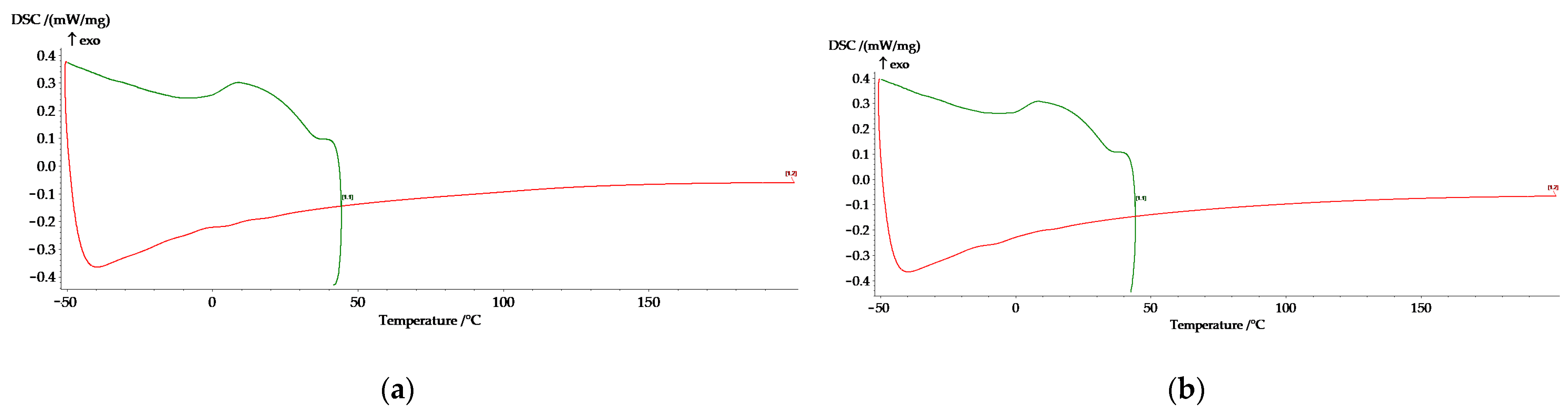
3.3. DSC Analysis for the FeMnSiAl Alloy

As shown in Figure 4, DSC curves are given from heating-cooling cycles. The DSC inflections of the curve (differentially obtained) are related to the solid-state thermal-induced transformation of ε (martensite) ⟷ γ (austenite); the main parameters extracted from these curves are given in Table 3. The transformation temperatures Ms (martensite start) and As (austenite start) are defined as the critical temperatures to start the fcc → hcp and the hcp → fcc martensitic transformations, respectively. Similarly, Mf (martensite finish) and Af (austenite finish) correspond to the temperatures where no further changes related to these transitions are detected [45,46]. Here, for the plain C and HR samples, we have registered the DSC flux variations only at cooling and we could evaluate the Ms and Mf points and a half M50 domain transformation. Table 3 shows the associated enthalpy (DH) with these transformations.
The temperature values for Ms and Mf are encouraging for medical applications; in this case, Ms is really close to body temperature. Potential thermo-mechanical treatments can be applied to enhance the effect and to move Mf closer to body temperature [47]. The Ms temperature is in agreement with the presence of ε-martensite observed in the SEM image and on the XRD pattern recorded at room temperature (~25 °C).
The lack of transformation on heating (the As and Af point on heating curves), at least in this case until 150 °C, is considered an issue for medical applications; however, the tension induced martensite can be investigated as a proper solution for medical applications.
Other studies mention that 97.26% of the FeMnSi-based SMA smart materials from the literature are not proper to be applied inside of the human body because the austenite start temperature (As) of these alloys with different compositions is far above the human body temperature. However, about 2.74% of the FeMnSi-based SMA (most of them with a higher percentage of Mn like Fe29Mn7Si5Cr and Fe29Mn7Si) have an austenite start temperature (As) of 41 °C, which is near 37 °C and makes it somehow possible to be used inside of the human body [46].

3.4. The pH Variation of the Electrolyte Solution and the Immersion Experiment

The pH variation of a solution can accelerate or decelerate the CR of the metallic material, and the pH modification can confirm the reactions that occur between the metal and the electrolyte solution. The iron corrosion (Fe) and Fe-based alloys in electrolyte solutions start with the anodic reaction [48,49]:
Fe → Fe+2 + 2e,
and the cathodic reaction:
H2O + 1/2O2 + 2e → 2OH
Iron-based alloys in contact with a near-neutral medium, such as those found in physiological fluids, exhibit a CR that depends largely on the cathodic reaction rate, which in turn depends on the dissolved oxygen amount [50]. Increasing the percentage of the dissolved oxygen in the corrosive medium increases the CR of iron. Conversely, decreasing the oxygen amount in contact with Fe leads to reduced corrosion rates.
In contact with an electrolyte solution, iron-based alloys react from the first moment through reactions (1) and (2), constantly changing the pH of the electrolyte solution. Figure 5 shows the pH variation of the Ringer’s electrolyte solution (volume of 20 mL/cm2) in contact with the FeMnSiAl alloy sample (total surface area of about 50 mm2) for 72 h. The chloride ions from the solution penetrated the metal substrate to compensate for the metal ions growth beneath the hydroxide layer. The metal chloride formed was then hydrolyzed to the hydroxide and free acid, thus the pH decreased in the pitting traces while the overall solution remained neutral.
During the first 24 h, for the HR sample, a constantly increase in the pH toward basic values is noticed with small inflections. A decrease of the solution pH, in the case of the C sample, is registered after approximately 15 h, due to the acids formation, specifically hydrochloric acid, (Equations (3)–(5)), resulting from the reactions that occur between the metal and the electrolyte solution. At first, a single layer of corrosion is formed which gradually increases in thickness, becoming two layers. The interface between the alloy and the electrolyte solution is formed from the first adjacent layer at the surface, which contains iron and oxygen. The reaction between Fe and hydroxyl ions (Equations (1) and (2)) led to the formation of an overlayer as a result of the following reaction:
Fe+2 + 2OH → Fe(OH2)
The further oxidation of Fe(OH2) to Fe+3 occurs due to water and dissolved oxygen, according to the following reaction:
Fe(OH2) + 1/2H2O + 1/4O2 → Fe(OH)3
The presence of Fe(OH)3 following the formation reaction attests to the stable oxide, which in the Pourbaix diagram can be identified at pH 6.4 [51,52]. In the study conducted by Hermawan et al. [38], the authors specify that Fe hydroxides can also take the form of oxides, e.g., hematite (Fe2O3), magnetite (Fe3O4), and wustite (FeO). In the same study, it was found that an autocatalytic reaction between chloride ions (Cl) and Fe ions could occur leading to the formation of pitting [53,54,55]:
Fe+2 + 2Cl → FeCl2 + H2O → Fe(OH2) + HCl
The outer layer also contains Fe and O, some Na, and is rich in C and Cl. FeCO3 and Fe-chlorine are found in the outer layer [56]. Si and Al are found in small percentages in the alloy; their oxidation will contribute to the possible formation of small quantities of silica or alumina, however, mainly it will participate in the complex oxide formation among Fe and Mn.
Taking into account the mass variation analysis upon immersion and the surface compounds determination, as well as the state of the surface, we characterized the degradation process and determined the stages of oxide formation, growth, and their detachment from the base material.
The mass variation and the surface chemical composition after 1, 3, and 7 days of immersion are given in Table 4 and Table 5. Only after the first immersion day, for both cases: C and respectively HR, an increase in mass (Table 4) is observed based on the compounds formed on the surface and still attached to the sample. In this stage, the samples start the corrosion process but not yet the degradation one. After the ultrasound cleaning (applied to detach the corrosion compounds formed on the surface), even after 24 h of immersion, the sample mass decreases in a small quantity (0.6 mg representing a loss of 0.01%) for a CR of 0.07 mm/year calculated with Equation (6) with: W: weight loss, A: exposed area, t: time, and ρ: density.
C R = 8.76 × 10 4 W A t ρ
The corrosion process starts from the first moment of contact between the metallic material and the electrolyte solution. After a short time, the passivation phenomenon occurs through the formation of an oxide protective film (in this case iron and manganese oxides in general and silicon and aluminum in smaller proportions). This protective barrier, in the case of titanium or zirconium, is very stable; it is penetrated by Cl ions but not quickly enough so that the material on the surface loses its integrity and connection with the base substrate, forming a layer of oxides, carbonates, and chlorides that detach from the substrate and pass into the electrolyte solution. Once this layer (more ceramic than metallic) peels away from the base material, it will have a new surface exposed to contact with the electrolyte solution, and the ion exchange cycle will continue until a new layer peels away from the underlying metallic substrate. The thickness of the oxide layers formed on the alloy surface from the beginning until the detachment from the base material is important for the degradation process of biocompatible materials, as the size of these compounds is a criterion for the acceptance of biodegradable and biocompatible materials as potential alloys for medical applications.
A higher CR was observed after 3 days of immersion (mass loss) compared to the 7 days immersion time, because the corrosion process was interrupted.
The average CR (between the three different immersion periods) is 0.15 mm/year for the C sample and 0.1 mm/year for the HR sample. These values recommend a material for plates or wires applications that is smaller than 500 μm for a long-time implant.
Beside the alloy’s main elements (Fe, Mn, Si and Al), we also identified oxygen on the surface, in high percentages, and carbon, chloride, and sodium before and after the ultrasound cleaning. The indicative values of the atomic and mass percentages of the identified elements are given in Table 5. The detector error is presented in order to properly approximate the variation percentages. The new elements resulted from the solution through various chemical reactions that occurred with the metal samples. SEM was used to characterize the material surface after immersion, before and after the ultrasound cleaning; images of the compounds (oxides, carbonates, chlorides etc.) formed on the surface are given in Figure 6. The oxidation process is continuous and the percentage of oxygen increased along with the immersion period. All of the alloy elements presented smaller percentages than the initial state, confirming that general corrosion, structural and chemical, occurs on the surface.
Sodium results mostly from unstable compounds remaining on the surface after the ultrasound cleaning, only in the case of the C sample. Carbon forms compounds with alloy elements, with a good affinity for iron and silicon, and is present in high percentages after the ultrasonic cleaning. Partial oxides pass into the solution (in some cases the percentage of C is higher after cleaning due to the decrease in the oxygen percentage). The elemental distribution on corroded surfaces is presented in Figure 7 and highlights the presence of the compounds after immersion, the loss of some after the ultrasound cleaning, and the pitting type corrosion presence under the oxidation layer.
It is known that the main reason why the CR of Fe increases with the addition of Mn is that the electronic potential of the metal decreases [53,54,55,56]; that is, the Fe-Mn alloy has a more active corrosion potential than pure Fe. This can be deduced from the value of the standard reduction potential of Fe of −0.44 V, and Mn which has a value of −1.18 V [57,58], where Si is −0.91 V and Al is −2.31 V. These differences are the main reasons for the lower CR of FeMnSiAl compared to pure Fe or other Fe-based alloys. When Fe is present, Mn can be oxidized by the following reaction [53]:
Mn → Mn+2 + 2e
As for Mn ions, they form solid corrosion products upon the reaction with anions [40]. The iron oxide layer often contains these products, according to studies [52]. Dargusch et al. [53] performed an in vitro study using Hank solution and observed two valence states of Mn in the Fe layer, Mn+2 and Mn+3, according to XPS analysis, thus they detected the following compounds: Mn(OH)2, Mn(OOH), and Mn2O3.
The reason for the much lower CR resulting from in vivo tests, compared with in vitro tests, is the dependence of Fe CR on dissolved oxygen. Dissolved oxygen in blood is about 3 mL/L or 4.3 mg/L, and, Hank’s solution, often used in studies as an electrolyte solution, is about 8 mg/L [59]. The conclusion that emerges from this is that the particular importance must be considered when performing in vitro tests on the amount of dissolved oxygen that influences the rate of Fe degradation.

3.5. Electro-Chemical and EIS Analysis

The Tafel plots obtained from electro-corrosion resistance tests of the alloys are giv-en in Figure 8a, and the main parameters are presented in Table 6. The HR sample presents a slightly higher inclination toward electro-corrosion (Figure 8a), compared to the C sample, based on internal tensions induced through thermo-mechanical treatment (heating at 950 °C and a 20% reduction degree). The electro-corrosion behavior was analyzed for the initial material (0 days C and HR material after mechanical grinding of up to 1000 with a very thin oxide layer produced by atmospheric corrosion) and after immersion for 3 and 9 days in the Ringer solution at 37 ± 1 °C. After the immersion, the samples presented a complex layer on top that influences the electro-corrosion behavior considerably.
The cyclic curve graph shows that the lower curve is the anodic branch of the volt-ammogram (the forward curve), the upper curve is the cathodic branch of the voltammogram (the return curve). At the same potential of the electrode, the intensity of the corrosion current, and therefore the corrosion speed, is higher on the anodic branch, probably because increased corrosion resulted on the anodic branch (the surface became rough as pitting corrosion occurred locally, expanded, and transformed in a very short period in general corrosion). In the C sample, based on a surface coarser structure, the casting defects present a cyclic voltammogram with more inflections, probably based on the corrosion sites formed on the surface which are deeper compared to the HR sample, confirming the SEM results from Figure 6d,h. The cathodic branch of the Tafel curve, bc, represents the cathodic reactions (Equation (2)) that are much greater than the anodic reactions (Equation (1)).
The icorr values are generally connected to the possible CR of the material. The HR sample presented a slightly larger corrosion current than the C one and a better stability to immersion. The highest corrosion current is registered on the immersed sample for three days. Between 3 and 9 days, the surface behavior changes based on the surface state of the material with a decrease in the corrosion current and rate. The results confirm the SEM data obtained. The CR was obtained from the Tafel extrapolation method matched with literature data. The CR in penetration units (such as mils/year, mpy), was calculated from icorr using the following equation [60]:
mpy = icorr × Λ × 1/ρ × ε
(Λ: 128,660 (equivalents.s.mil)/(Coulombs.cm.years), icorr = the corrosion current density in Amps/cm2 (Amp = 1 Coulomb/s); ρ = density (7.86 g/cm3, for iron-based alloys), and ε = equivalent weight (27.56 g/equivalent, for iron)).
The corrosion rates are higher for the immersed samples compared with the initial atmospheric corroded samples with the biggest value for the 3 days immersed sample and a smaller rate after 9 days (Table 6), a fact that confirms the cyclic degradation behavior mentioned earlier.
Compared to the FeMnSi alloy, the icorr is, in all cases, more than five times bigger [56]. The degradation rate increase by the addition of Al is also due to the irregular spreading of Al at the grain boundary, the formation of Al phases, or compounds that will favor the differences between different corrosion potential zones (similar to the formation of micropiles).
EIS was used to characterize the corrosion behavior in both states of the alloy (C and HR). The experiments were registered for the initial sample after 3 and 9 days of immersion, respectively, in Ringer solution. The results show that, for these FeMnSiAl-based alloys, an equivalent circuit describes their behavior in an electrolyte solution (Table 7) with a single time constant. The Randles-type circuit shows that the corrosion process occurs through a single chemical reaction (most likely iron corrosion with the formation of soluble and insoluble products) over the entire sample surface (generalized corrosion).
The circuit elements (Table 7) have the following meanings: Rs—the electrolyte re-sistance between the working electrode and the reference electrode; Rct—the resistance to the charge transfer through the electric double layer (ct → charge transfer), thereby controlling the speed of the corrosion process; and CPE—the element of constant phase, which, in theory, would represent the capacity of the electric double layer (Cdl), but here it has the meaning of an imperfect capacitor (n < 1). Imperfections can be mechanical (rough surface) and/or chemical (uneven chemical composition).
The R (QR) circuit fits the experimental curve very well. The admission of this circuit indicates that the complex layer on the sample surface is forcibly divided into two layers: SDE (electric double layer where the reaction occurs) and another layer. In the Nyquist diagram, the experimental curve shows a negative loop in the low frequency range. This distortion is most often attributed to an inductive behavior of the electrochemical system due to the process of the adsorption of intermediates on the surface of the electrode (sample) [56]. Here, it would most likely be the adsorption of Fe or Fe2O3 (Figure 9). Both the Nyquist and Bode curves indicate that the experimental data are suitable for a circuit with a single time constant, the R (QR) circuit.
The parameters Rct and Q describe the processes that occur in the formed layer at the interface between the electrolyte and the superficial layer. Rct represents the pore resistance during the penetration process and Q corresponds to the constant phase of the elements that form the coating layer.
The complex oxides-hydroxides-carbonates influence the corrosion resistance behavior, which is higher for the C sample compared to the HR sample, as confirmed by the Rct variation from the initial state to the immersed samples (3 or 9 days). The repetitive nature of the corrosion process was also observed through EIS experiments, and degradation occurred between 3–4 days of immersion, and a different behavior was observed after this period. Both samples present a similar behavior after the Ringer immersion (Figure 9a,b), with different values based on the cover layer formed on the surface.
The alloying of the FeMnSi alloy with aluminum led to obtaining a transformation in the solid state and in the cast alloy, not only in the rolled or heat-treated one, in the range of transformation temperatures 35–5 °C. The hot rolling of the material led to a generalization of corrosion, a controlled change in the pH of the electrolyte solution after the first 24 h, and a slight increase in the corrosion speed of the material.

4. Conclusions

An Fe-based SMA with a new chemical composition was obtained and analyzed as a potential biodegradable metallic material. The main conclusions derived from the experimental results are:
  • a homogeneous alloy was obtained through arc-melting and induction furnace re-melting;
  • a solid-state transformation was recorded using DSC at cooling with the Ms temperature near the human body temperature, encouraging the potential of this material for medical applications;
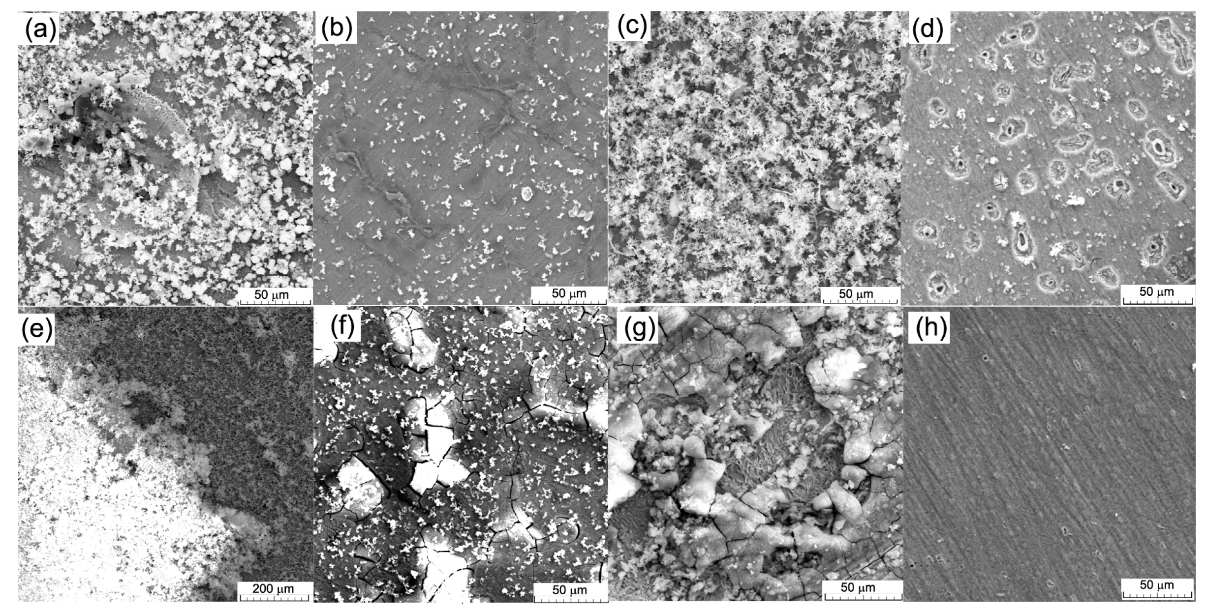
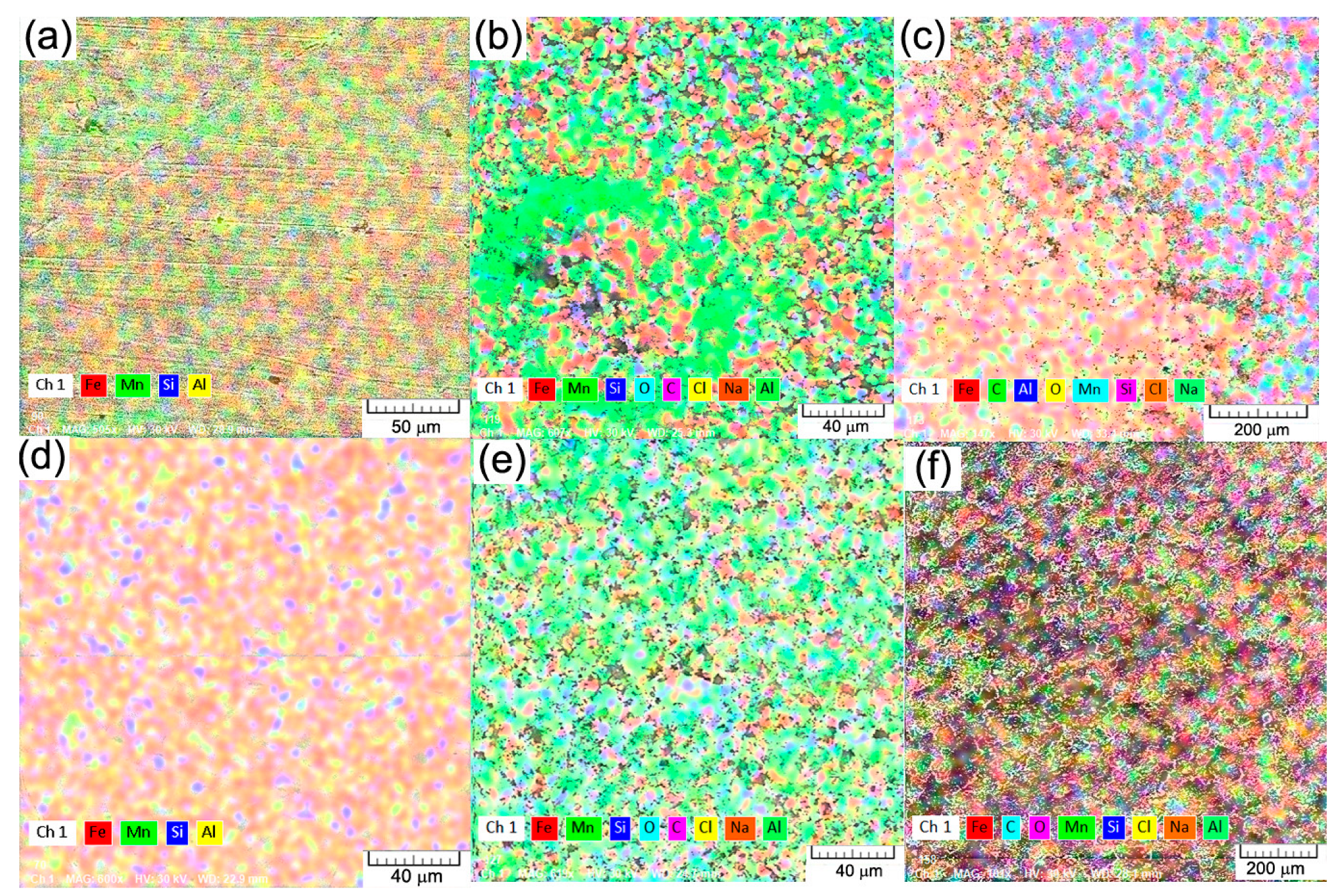
  • different corrosion stages of the Ringer solution were characterized through a mass loss analysis (the CR was determined) and chemical composition determinations (the presence of oxides from day one, the carbon growth based on the surface compounds with high stability, the appearance of chloride and sodium-based compounds with low stability on the surface, a combination of pitting with general corrosion was observed on the surface);
  • along with the immersion period, the CR (electro-corrosion in case of galvanic couple) varies considering the complex layer properties formed on top of the surface;
  • further investigation on the SME of this smart material with corrosion evolution must be fulfilled to implement it in medical applications; however, currently the results are promising in this direction. More investigation on cytotoxicity of the alloy must be performed and the effect of the aluminum alloying percentage on the possibility of influencing the appearance of different diseases, such as Alzheimer, can be taken in consideration.

Author Contributions

Conceptualization, N.C. and M.A.; formal analysis, B.I., R.C. (Romeu Chelariu), G.Z., and N.M.L.; funding acquisition, N.C.; investigation, A.-M.R., I.V., B.I., N.C., G.Z., C.P., N.M.L., M.A., and A.M.M.; methodology, A.-M.R., I.V., B.I., R.C. (Ramona Cimpoeșu), C.P., M.A., and A.M.M.; software, G.Z.; validation, R.C. (Romeu Chelariu); writing—original draft, A.-M.R., R.C. (Ramona Cimpoeșu), N.C., and M.A.; writing—review & editing, N.C. All authors have read and agreed to the published version of the manuscript.

Funding

This work was supported by a grant from the Ministry of Research, Innovation and Digitalization, CNCS—UEFISCDI, project number PN-III-P1-1.1-TE-2021-0702, within PNCDI III.

Data Availability Statement

Not applicable.

Conflicts of Interest

The authors declare no conflict of interest.

References

  1. Rapetto, C.; Leoncini, M. Magmaris: A new generation metallic sirolimus-eluting fully bioresorbable scaffold: Present status and future perspectives. J. Thorac. Dis. 2017, 9, S903. [Google Scholar] [CrossRef] [Green Version]
  2. Bowen, P.K.; Drelich, J.; Goldman, J. Zinc Exhibits Ideal Physiological Corrosion Behavior for Bioabsorbable Stents. Adv. Mater. 2013, 25, 2577–2582. [Google Scholar] [CrossRef]
  3. Bowen, P.K.; Shearier, E.R.; Zhao, S.; Guillory, R.J.; Zhao, F.; Goldman, J.; Drelich, J.W. Biodegradable Metals for Cardiovascular Stents: From Clinical Concerns to Recent Zn-Alloys. Adv. Healthcare Mater. 2016, 5, 1121–1140. [Google Scholar] [CrossRef] [Green Version]
  4. Venezuela, J.; Dargusch, M.S. The influence of alloying and fabrication techniques on the mechanical properties, biodegradability and biocompatibility of zinc: A comprehensive review. Acta Biomater. 2019, 87, 1–40. [Google Scholar]
  5. Hermawan, H.; Purnama, A.; Dube, D.; Couet, J.; Mantovani, D. Fe–Mn alloys for metallic biodegradable stents: Degradation and cell viability studies. Acta Biomater. 2010, 6, 1852–1860. [Google Scholar] [CrossRef]
  6. Peuster, M.; Wohlsein, P.; Brugmann, M.; Ehlerding, M.; Seidler, K.; Fink, C.; Brauer, H.; Fischer, A.; Hausdorf, G. A novel approach to temporary stenting: Degradable cardiovascular stents produced from corrodible metal-results 6–18 months after implantation into New Zealand white rabbits. Heart 2001, 86, 563–569. [Google Scholar] [CrossRef] [Green Version]
  7. Francis, A.; Yang, Y.; Virtanen, S.; Boccaccini, A.R. Iron and iron-based alloys for temporary cardiovascular applications. J. Mater. Sci. Mater. Med. 2015, 26, 138. [Google Scholar]
  8. He, J.; He, F.L.; Li, D.; Liu, Y.L.; Liu, Y.Y.; Ye, Y.J.; Yin, D.C. Advances in Fe-based bio-degradable metallic materials. RSC Adv. 2016, 6, 112819–112838. [Google Scholar] [CrossRef]
  9. Peuster, M.; Hesse, C.; Schloo, T.; Fink, C.; Beerbaum, P.; Schnakenburg, C.V. Long term biocompatibility of a corrodible peripheral iron stent in the porcine descending aorta. Biomaterials 2006, 27, 4955–4962. [Google Scholar] [CrossRef]
  10. Sharma, P.; Pandey, P.M. Corrosion behaviour of the porous iron scaffold in simulated body fluid for biodegradable implant application. Mater. Sci. Eng. C 2019, 99, 838–852. [Google Scholar] [CrossRef]
  11. Hermawan, H.; Alamdari, H.; Mantovani, D.; Dubé, D. Iron-manganese: New class of de-gradable metallic biomaterials prepared by powder metallurgy. Powder Metall. 2008, 51, 38–45. [Google Scholar] [CrossRef]
  12. Kraus, T.; Moszner, F.; Fischerauer, S.; Fiedler, M.; Martinelli, E.; Eichler, J.; Witte, F.; Willbold, E.; Schinhammer, M.; Meischel, M. Biodegradable Fe-based alloys for use in osteo-synthesis: Outcome of an in vivo study after 52 weeks. Acta Biomater. 2014, 10, 3346–3353. [Google Scholar] [CrossRef]
  13. Schinhammer, M.; Steiger, P.; Moszner, F.; Loffler, J.F.; Uggowitzer, P.J. Degradation performance of biodegradable FeMnC(Pd) alloys. Mater. Sci. Eng. C 2013, 33, 1882–1893. [Google Scholar] [CrossRef]
  14. Gebert, A.; Kochta, F.; Voß, A.; Oswald, S.; Fernandez-Barcia, M.; Kühn, U.; Hufenbach, J. Corrosion studies on Fe-30Mn-1C alloy in chloride-containing solutions with view to biomedical application. Mater. Corros. 2018, 69, 167–177. [Google Scholar] [CrossRef] [Green Version]
  15. Harjanto, S.; Pratesa, Y.; Suharno, B.; Syarif, J. Corrosion Behavior of Fe-Mn-C Alloy as Degradable Materials Candidate Fabricated via Powder Metallurgy Process. Adv. Mater. Res. 2012, 576, 386–389. [Google Scholar] [CrossRef]
  16. Xu, W.; Lu, X.; Tan, L.; Yang, K. Study on properties of a novel biodegradable Fe-30Mn-1C alloy. Acta Metall. Sinica 2011, 47, 1342–1347. [Google Scholar]
  17. Schinhammer, M.; Hänzi, A.C.; Löffler, J.F.; Uggowitzer, P.J. Design strategy for biodegradable Fe-based alloys for medical applications. Acta Biomater. 2010, 6, 1705–1713. [Google Scholar] [CrossRef]
  18. Hermawan, H. Biodegradable Metals—From Concept to Applications; Springer Science & Business Media: Berlin/Heidelberg, Germany, 2012. [Google Scholar]
  19. Sotoudeh Bagha, P.; Sheibani, S.; Khakbiz, M.; Ebrahimi-Barough, S.; Hermawan, H. Novel antibacterial biodegradable Fe-Mn-Ag alloys produced by mechanical alloying. Mater. Sci. Eng. C 2018, 88, 88–94. [Google Scholar] [CrossRef] [Green Version]
  20. Niendorf, T.; Brenne, F.; Hoyer, P.; Schwarze, D.; Schaper, M.; Grothe, R.; Wiesener, M.; Grundmeier, G.; Maier, H.J. Processing of New Materials by Additive Manufacturing: Iron-Based Alloys Containing Silver for Biomedical Applications Metall. Mater. Trans. A 2015, 46, 2829–2833. [Google Scholar] [CrossRef]
  21. Liu, B.; Zheng, Y.F.; Ruan, L. In vitro investigation of Fe30Mn6Si shape memory alloy as potential biodegradable metallic material. Mater. Lett. 2011, 65, 540–543. [Google Scholar] [CrossRef]
  22. Drevet, R.; Zhukova, Y.; Malikova, P.; Dubinsky, S.; Korotitskiy, A.; Pustov, Y.; Prokoshkin, S. Martensitic Transformations and Mechanical and Corrosion Properties of Fe-Mn-Si Alloys for Biodegradable Medical Implants. Metall. Mater. Trans. A 2018, 49, 1006–1013. [Google Scholar] [CrossRef]
  23. Rahman, R.A.; Juhre, D.; Halle, T.; Mehmood, S.; Asghar, W. Types, DSC Thermal Characterization of Fe-Mn-Si based Shape Memory, Smart Materials and their Feasibility for Human Body in Terms of Austenitic Start Temperatures. J. Eng. Technol. 2019, 8, 185–206. [Google Scholar]
  24. Rahman, R.A.; Juhre, D.; Halle, T. Review of Types, Properties, and Importance of Ferrous Based Shape Memory Alloys. Korean J. Mater. Res. 2018, 28, 381–390. [Google Scholar] [CrossRef]
  25. Koyama, M.; Sawaguchi, T.; Ogawa, K.; Kikuchi, T.; Murakami, M. The effects of thermomechanical training treatment on the deformation characteristics of Fe–Mn–Si–Al alloys. Mater. Sci. Eng. A 2008, 497, 353–357. [Google Scholar] [CrossRef]
  26. Yang, H.K.; Tian, Y.Z.; Zhang, Z.J.; Zhang, Z.F. Different strain rate sensitivities between Fe–22Mn–0.6C and Fe– 30Mn–3Si–3Al twinning-induced plasticity steels. Mater. Sci. Eng. A 2016, 655, 251–255. [Google Scholar]
  27. Mahato, B.; Shee, S.K.; Sahu, T.; Ghosh Chowdhury, S.; Sahu, P.; Portere, D.A.; Karjalainene, L.P. An effective stacking fault energy viewpoint on the formation of extended defects and their contribution to strain hardening in a Fe–Mn–Si–Al twinning-induced plasticity steel. Acta Mater. 2015, 86, 69–79. [Google Scholar]
  28. Idrissi, H.; Renard, K.; Ryelandt, L.; Schryvers, D.; Jacques, P.J. On the mechanism of twin formation in Fe–Mn–C TWIP steels. Acta Mater. 2010, 58, 2464–2476. [Google Scholar] [CrossRef]
  29. Idrissi, H.; Renard, K.; Schryvers, D.; Jacques, P.J. TEM investigation of the formation mechanism of deformation twins in Fe–Mn–Si–Al TWIP steels. Philos. Mag. 2013, 93, 4378–4391. [Google Scholar] [CrossRef]
  30. Feng, Y.P.; Blanquer, A.; Fornell, J.; Zhang, H.; Solsona, P.; Baró, M.D.; Suriñach, S.; Ibáñez, E.; García-Lecina, E.; Wei, X.; et al. Novel Fe-Mn-Si-Pd alloys: Insights into mechanical, magnetic, corrosion resistance and biocompatibility performances. J. Mater. Chem. B 2016, 4, 6402–6412. [Google Scholar] [CrossRef] [Green Version]
  31. Moravej, M.; Mantovani, D. Biodegradable metals for cardiovascular stent application: Interests and new opportunities. Int. J. Mol. Sci. 2011, 12, 4250–4270. [Google Scholar] [CrossRef] [Green Version]
  32. Nie, Y.; Chen, G.; Peng, H.; Tang, S.; Zhou, Z.; Pei, F.; Shen, B. In vitro and 48 weeks in vivo performances of 3D printed porous Fe-30Mn biodegradable scaffolds. Acta Biomater. 2021, 121, 724–740. [Google Scholar] [CrossRef] [PubMed]
  33. Drynda, A.; Hassel, T.; Bach, F.W.; Peuster, M. In vitro and in vivo corrosion properties of new iron–manganese alloys designed for cardiovascular applications. J. Biomed. Mater. Res. B 2015, 103, 649–660. [Google Scholar] [CrossRef] [PubMed]
  34. Nayak, P.; Biswal, A.K.; Sahoo, S.K. Processing and characterization of Fe-35Mn biodegradable metallic materials. Mater. Today Proc. 2020, 33, 5284–5289. [Google Scholar] [CrossRef]
  35. Boguszewska-Czubara, A.; Pasternak, K. Silicon in medicine and therapy. J. Elem. 2011, 16, 489–497. [Google Scholar] [CrossRef]
  36. Rahman, R.A.U.; Juhre, D.; Halle, T. Review of applications of ferrous based shape memory smart materials in engineering and in biomedical sciences. Pak. J. Eng. Appl. Sci. 2019, 24, 32–49. [Google Scholar]
  37. Bosiers, M.; Peeters, P.; D’Archambeau, O.; Hendriks, J.; Pilger, E.; Duber, C.; Zeller, T.; Gussmann, A.; Lohle, P.N.M.; Minar, E.; et al. AMS INSIGHT—Absorbable metal stent implantation for treatment of below-the-knee critical limb ischemia: 6-month analysis. Cardiovasc. Intervent. Radiol. 2009, 32, 424–435. [Google Scholar] [CrossRef] [Green Version]
  38. Hermawan, H.; Dubé, D.; Mantovani, D. Degradable metallic biomaterials: Design and development of Fe–Mn alloys for stents. J. Biomed. Mater. Res. A 2010, 93, 1–11. [Google Scholar] [CrossRef]
  39. Kocijan, A.; Paulin, I.; Donik, C.; Hocevar, M.; Zelic, K.; Godec, M. Influence of different production processes on the biodegradability of an FeMn17 alloy. Mater. Tehnol. 2016, 50, 805–811. [Google Scholar]
  40. Kirindi, T.; Sari, U. The effects of austenite phase deformation on microstructure and magnetic properties in Fe-13.4%Mn-5.2%Mo alloy. J. Mater. Sci. 2011, 46, 6378–6383. [Google Scholar]
  41. Sari, U.; Kirindi, T.; Yueksel, M.; Agan, S. Influence of Mo and Co on the magnetic properties and martensitic transformation characteristics of a Fe-Mn alloy. J. Alloys Compd. 2009, 476, 160–163. [Google Scholar] [CrossRef]
  42. Guerrero, L.M.; La Roca, P.; Malamud, F.; Baruj, A.; Sade, M. Composition effects on the fcc-hcp martensitic transformation and on the magnetic ordering of the fcc structure in Fe-Mn-Cr alloys. Mater. Des. 2017, 116, 127–135. [Google Scholar] [CrossRef]
  43. Pan, M.M.; Zhang, X.M.; Zhou, D.; Misra, R.D.K.; Chen, P.; Su, X. Bin On the significance of C and Co on shape memory performance of Fe–Mn–Si–Cr–Ni shape memory alloy. Mater. Sci. Eng. A 2020, 786, 139412. [Google Scholar] [CrossRef]
  44. Cotes, S.; Fernández Guillermet, A.; Sade, M. Phase stability and fcc/hcp martensitic trans-formation in Fe-Mn-Si alloys Part I. Experimental study and systematics of the Ms and As temperatures. J. Alloys Compd. 1998, 278, 231–238. [Google Scholar] [CrossRef]
  45. Gurau, C.; Gurau, G.; Tolea, F.; Popescu, B.; Banu, M.; Bujoreanu, L.G. The Effect of the In-Situ Heat Treatment on the Martensitic Transformation and Specific Properties of the Fe-Mn-Si-Cr Shape Memory Alloys Processed by HSHPT Severe Plastic Deformation. Materials 2021, 14, 4621. [Google Scholar] [CrossRef]
  46. Collazo, A.; Figueroa, R.; Mariño-Martínez, C.; Pérez, C. Micro-structure and Thermomechanical Characterization of Fe-28Mn-6Si-5Cr Shape Memory Alloy. Metals 2021, 11, 649. [Google Scholar] [CrossRef]
  47. Feng, Y.P.; Gaztelumendi, N.; Fornell, J.; Zhang, H.Y.; Solsona, P.; Baro, M.D.; Surinach, S.; Ibanez, E.; Barrios, L.; Pellicer, E.; et al. Mechanical properties, corrosion performance and cell viability studies on newly developed porous Fe-Mn-Si-Pd alloys. J. Alloys Compd. 2017, 724, 1046–1056. [Google Scholar] [CrossRef] [Green Version]
  48. Stanford, N.; Dunne, D.P. Effect of Si on the reversibility of stress-induced martensite in Fe-Mn-Si shape memory alloys. Acta Mater. 2010, 58, 6752–6762. [Google Scholar] [CrossRef]
  49. Zheng, Y.F.; Gu, X.N.; Witte, F. Biodegradable metals, Mater. Sci. Eng. R. 2014, 77, 1–34. [Google Scholar] [CrossRef]
  50. Qi, Y.; Li, X.; He, Y.; Zhang, D.; Ding, J. Mechanism of acceleration of iron corrosion by a polylactide coating. ACS Appl. Mater. Interfaces 2019, 11, 202–218. [Google Scholar] [CrossRef]
  51. Revie, W.R.; Uhlig, H.H. Corrosion and Corrosion Control: An Introduction to Corrosion Science and Engineering, 4th ed.; John and Wiley and Sons: Hoboken, NJ, USA, 2008. [Google Scholar]
  52. Suárez Muñoz, M.; Melián Rodríguez, C.; Gelen Rudnikas, A.; Díaz Rizo, O.; Martínez-Santos, M.; Ruiz-Romera, E.; Fagundo Castillo, J.R.; Pérez-Gramatges, A.; Martínez-Villegas, N.V.; Blanco Padilla, D.; et al. Physico-chemical characterization, elemental speciation and hydrogeochemical modeling of river and peloid sediments used for therapeutic uses. Appl. Clay Sci. 2015, 104, 36–47. [Google Scholar] [CrossRef]
  53. Dargusch, M.S.; Dehghan-manshadi, A.; Shahbazi, M.; Venezuela, J.; Tran, X.Q.; Song, J.; Liu, N.; Xu, C.; Ye, Q.; Wen, C. Exploring the Role of Manganese on the Microstructure, Mechanical Properties, Biodegradability, and Biocompatibility of Porous Iron-Based Scaffolds. ACS. Biomater. Sci. Eng. 2019, 5, 1686–1702. [Google Scholar] [CrossRef] [PubMed]
  54. Donik, C.; Kraner, J.; Kocijan, A.; Paulin, I.; Godec, M. Evolution of the ε and γ phases in biodegradable Fe–Mn alloys produced using laser powder-bed fusion. Sci. Rep. 2021, 11, 19506. [Google Scholar] [CrossRef] [PubMed]
  55. Zhang, E.; Xu, L.; Yu, G.; Pan, F.; Yang, K. In vivo evaluation of biodegradable magnesium alloy bone implant in the first 6 months implantation. J. Biomed. Mater. Res. A 2009, 90, 882–893. [Google Scholar] [CrossRef] [PubMed]
  56. Roman, A.M.; Geanta, V.; Cimpoesu, R.; Munteanu, C.; Lohan, N.M.; Zegan, G.; Cernei, E.R.; Ionita, I.; Cimpoesu, N.; Ioanid, N. In-Vitro Analysis of FeMn-Si Smart Biodegradable Alloy. Materials 2022, 15, 568. [Google Scholar] [CrossRef] [PubMed]
  57. Liu, B.; Zheng, Y.F. Effects of alloying elements (Mn, Co, Al, W, Sn, B, C and S) on bio-degradability and in vitro biocompatibility of pure iron. Acta Biomater. 2011, 7, 1407–1420. [Google Scholar] [CrossRef]
  58. Ravanbakhsh, S.; Paternoster, C.; Barucca, G.; Mengucci, P.; Gambaro, S.; Lescot, T.; Chevallier, P.; Fortin, M.A.; Mantovani, D. Improving the radiopacity of Fe-Mn biodegradable metals by magnetron-sputtered W-Fe-Mn-C coatings: Application for thinner stents. Bioact. Mater. 2021, 12, 64–70. [Google Scholar] [CrossRef]
  59. Kawashima, K.; Asami, K.; Hashimoto, K. Effect of manganese on the corrosion behaviour of chromium-bearing amorphous metal-metalloid alloys. Sci. Rep. Res. Inst. Tohoku Univ. Phys. Chem. Metall. 1981, 29, 276–283. [Google Scholar]
  60. Ijsseling, F.P. Application of electrochemical methods of corrosion rate determination to system involving corrosion product layers. Br. Corros. J. 1986, 21, 95–101. [Google Scholar] [CrossRef]
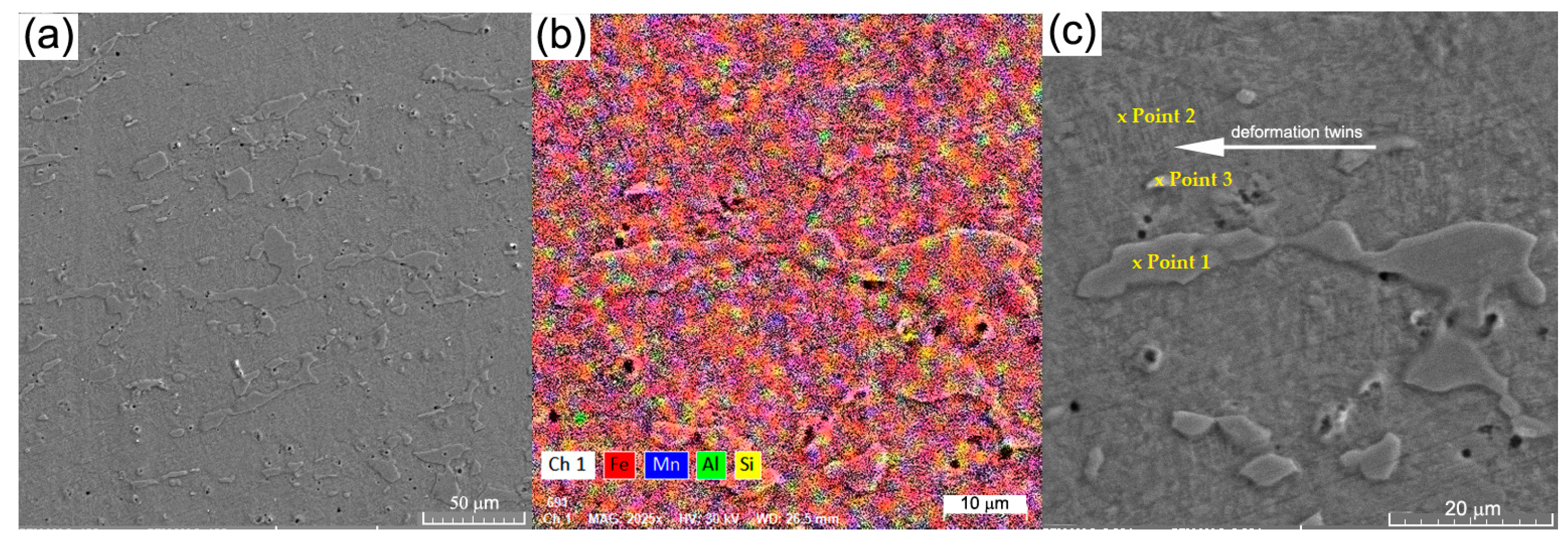
Figure 1. NDT analysis of melted FeMnSiAl alloy for the C sample: (a) first melt; (b) after five re-melts; and for the HR sample: (c) first melt; (d) after five re-melts.
Crystals 13 00109 g001
Figure 2. SEM images of the FeMnSi-Al structure: (a) structure; (b) elemental distributions; (c) area selection for the phase chemical composition determination.
Crystals 13 00109 g002
Figure 3. XRD patterns of HR FeMnSi and FeMnSi-Al alloys: (a) FeMnSi and FeMnSi-Al diffractograms; (b) main peaks (Gauss deconvolution).
Crystals 13 00109 g003
Figure 4. DSC diagrams for: (a) C; (b) HR samples.
Crystals 13 00109 g004
Figure 5. The pH variation values recorded during 72 h of immersion in Ringer’s solution for the C and HR FeMnSiAl samples.
Crystals 13 00109 g005
Figure 6. SEM images: (a) C sample after 1 day immersion (1 kx); (b) after ultrasound cleaning (5 kx); (c) HR sample after 1 day immersion (1 kx); (d) after ultrasound cleaning (5 kx); (e) C sample after 7 days immersion (1 kx); (f) and after ultrasound cleaning (2 kx); (g) HR sample after 7 days immersion (1 kx); (h) after ultrasound cleaning (2 kx).
Crystals 13 00109 g006
Figure 7. The distribution of chemical elements on the surface for the C sample: (a) initial state; (b) after 1-day immersion; (c) after 7 days immersion; HR: (d) initial state; (e) after 1-day immersion; (f) after 7 days immersion.
Crystals 13 00109 g007
Figure 8. The electro-corrosion results: (a) the Tafel plots of C and HR FeMnSiAl alloy; (b) the cyclic curves voltammograms.
Crystals 13 00109 g008
Figure 9. Electrochemical measurements of tested samples for: (a) Bode plots; (b) Nyquist plots after 1 h in Ringer solution.
Crystals 13 00109 g009
Table 1. The chemical composition determinations (five times average values).
Chem. Comp./AreaFeMnSiAl
wt%at%wt%at%wt%at%wt%at%
General (1 mm2)80.2575.7914.2513.663.055.722.474.82
Point 181.2376.4312.8712.313.005.862.95.64
Point 281.0176.4713.4012.853.125.862.464.81
Point 378.8074.9416.4215.872.915.51.883.69
EDS error %1.90.470.20.19
St. dev. (20 determinations on the same area): Fe: ±0.2; Mn: ±0.1; Si: ±0.1 and Al: ±0.1.
Table 2. Characteristic diffraction peaks for FeMnSi and FeMnSi-Al alloys.
FeMnSi AlloyFeMnSi-Al AlloyPhaseMiller Indices
PeakAngle (2θ)Angle (2θ)hkl
141.237741.0715ε-Fe(ss)100
244.208543.5743γ-Fe(ss)111
344.656043.9838α-Fe(ss)110
446.984746.8430ε-Fe(ss)002
5-50.4888γ-Fe(ss)200
6-61.6867ε-Fe(ss)102
764.6965-α-Fe(ss)200
8-74.5462γ-Fe(ss)220
982.125682.8594α-Fe(ss)211
Table 3. DSC results from the cooling curve of FeMnSiAl alloy.
SampleMs
[°C]
M50
[°C]
Mf
[°C]
DH
[KJ/kg]
C sample35.79.20.111.87
HR sample35.18.10.39.55
Table 4. CR determined by each mass gain/loss of the samples subjected to immersion tests and subsequent cleaning in the ultrasonic bath (immersion time for 1, 3, and 7 days; lots of three samples for each immersion period were used and labeled the average values).
Immersion Time/State of the Samples1 Day3 Days7 Days
Cast Sample (C)Hot-Rolled Sample (HR)Cast Sample (C)Hot-Rolled Sample (HR)Cast Sample (C)Hot-Rolled Sample (HR)
Initial mass (mg)5637.6597.05681.5553.95660.0547.9
Mass after immersion (mg)5638.4
(+0.8)
597.2
(+0.2)
5676.6
(−4.9)
553.5
(−0.4)
5654.5
(−5.5)
545.9
(−2.0)
Mass after ultrasonic cleaning (mg)5637.0
(−0.6)
596.5
(−0.5)
5675.0
(−6.5)
551.9
(−2.0)
5652.3
(−7.7)
544.5
(−3.4)
CR (mm/year) (samples areas C = 4.2 cm2 and L = 2.7 cm2)0.0700.0910.2530.1210.1280.088
Standard deviation: ±0.1 mg.
Table 5. EDS analysis after the immersion tests and ultrasound cleaning (immersion time for 1 and 7 days).
Chemical Elements/State of the SamplesFeMnSiAlOCClNa
wt%at%wt%at%wt%at%wt%at%wt%at%wt%at%wt%at%wt%at%
1 day
(I)
CI43.2919.258.053.641.381.222.212.0332.5950.5710.4021.501.180.820.900.98
I+
UC
47.7423.0710.845.321.631.562.292.2925.2742.6110.5223.641.220.930.490.57
HRI46.9221.497.523.501.090.991.301.2333.0152.778.9319.020.940.670.300.33
I+
UC
49.6224.0512.045.931.281.241.611.6221.9237.1013.2429.850.280.22--
7 days
(I)
CI44.2017.700.310.130.240.190.100.0841.8258.4712.0422.420.730.460.560.54
I+
UC
42.3218.967.823.561.981.774.193.8833.0851.738.8718.480.690.491.051.14
HRI39.2916.787.053.061.641.392.602.2935.0452.2310.6121.072.041.371.741.81
I+
UC
47.3921.4410.824.981.541.381.881.7619.5730.9118.7939.53----
EDS error%1.380.350.120.214.914.480.090.20
C: cast, HR: hot rolled, I: after immersion, I + UC: after immersion and ultrasound cleaning; StDev: Fe: ±0.9, Mn: ±0.7, Si: ±0.22, Al: ±0.3, O: ±0.2, C: ±0.1, Cl: ±0.1, Na: ±0.1.
Table 6. Linear (Tafel) potentiometry parameters in Ringer solution (three electrodes cell).
AlloyE(I = 0)
(mV)
icorr
(µA)
vcorr
mpy
βc
(mV/dec)
βa
(mV/dec)
FeMnSiAl (C)
0 days
74110.1154.16832261
3 days67169.43371.91664260
9 days59023.51125516293
FeMnSiAl (HR)
0 days
−77514.7679.09432770
3 days77516.2286.8637477
Table 7. The values of the equivalent circuit for the FeMnSiAl alloy, C, and HR samples.
FeMnSiAl (C) FeMnSiAl (HR)
R(QR)Crystals 13 00109 i001
0 Days3 Days9 Days0 Days3 Days
Rs (ohm.cm2)104.573.0748.99170.3167.2
Q 103 (S.sn/cm2)0.57450.34830.4530.53940.5566
n0.69140.54750.64680.65850.6476
Rct (ohm.cm2)127541083937706819.3
Disclaimer/Publisher’s Note: The statements, opinions and data contained in all publications are solely those of the individual author(s) and contributor(s) and not of MDPI and/or the editor(s). MDPI and/or the editor(s) disclaim responsibility for any injury to people or property resulting from any ideas, methods, instructions or products referred to in the content.

